si4708-09-B
Skyworks Si4700 01 02 03 08 09评估板快速入门指南说明书
AN235Si4700/01/02/03/08/09 E VALUATION B OARD Q UICK-S TART G UIDE Thank you for purchasing the Skyworks Solutions Si4700/01/02/03/08/09 FM Tuner Evaluation Board (EVB). The EVB and associated software have been designed to speed the overall development process and decrease required development time. We look forward to working with you and have posted support articles, answers to fre-quently asked questions, and application notes on the Si47xx Customer Support Site at https:///en/Support.Note: A more comprehensive user's guide for configuring your system is available on the EVB CD (Si4700/01/02/03 Evalua-tion Board User's Guide or Si4708/09 Evaluation Board User’s Guide) and on the Si47xx Customer Support Site. If you have any difficulty or questions about any of the steps below, please consult the EVB users guide prior to plugging in your EVB.1.Make sure any prior versions of the GUI are removed prior to installation of the GUI application softwareshipped with the evaluation board kit.- You can use "Add or Remove Programs" in the Windows control panel to remove the old version of the GUI.2.Insert the Skyworks Solutions CD into host CD drive.3.Install the Development GUI located in CD:\Si47xx\Setup.exe.- The setup program may prompt to install the DotNetFramework which is required for the program to function.This may be installed from the DotNetFramework directory on the Installation CD or from the Microsoftwebsite.4.Connect the USB cable to the evaluation board USB connector.5.Make sure that switch SW1 is in the USB position to use USB power.unch the Si47xx Development GUI.General Debugging GuidelinesIf your EVB is not functional, please refer to the following troubleshooting tips.1.Make sure the EVB is recognized by your PC. Right-click on "My Computer", and select "Properties" →"Hardware" → "Device Manager". Under "Human Interface Devices", select each "HID-Compliant Device" →“Details" entry, and confirm one contains "VID_10C4&PID_8193."2.If the EVB is not recognized by the GUI, uninstall .NET Framework V2.0, and reinstall from Microsoft's WindowsUpdate.SkyworksSolutions,Inc.•Phone[781]376-3000•Fax[781]376-3100•*********************•Rev. 0.6 • Skyworks Proprietary Information • Products and Product Information are Subject to Change Without Notice • September 8, 2021Copyright © 2021 Skyworks Solutions, Inc. All Rights Reserved.Information in this document is provided in connection with Skyworks Solutions, Inc. (“Skyworks”) products or services. These materials, including the information contained herein, are provided by Skyworks as a service to its customers and may be used for informational purposes only by the customer. Skyworks assumes no responsibility for errors or omissions in these materials or the information contained herein. Skyworks may change its documentation, products, services, specifications or product descriptions at any time, without notice. Skyworks makes no commitment to update the materials or information and shall have no responsibility whatsoever for conflicts, incompatibilities, or other difficulties arising from any future changes.No license, whether express, implied, by estoppel or otherwise, is granted to any intellectual property rights by this document. Skyworks assumes no liability for any materials, products or information provided hereunder, including the sale, distribution, reproduction or use of Skyworks products, information or materials, except as may be provided in Skyworks’ Terms and Conditions of Sale.THE MATERIALS, PRODUCTS AND INFORMATION ARE PROVIDED “AS IS” WITHOUT WARRANTY OF ANY KIND, WHETHER EXPRESS, IMPLIED, STATUTORY, OR OTHERWISE, INCLUDING FITNESS FOR A PARTICULAR PURPOSE OR USE, MERCHANTABILITY, PERFORMANCE, QUALITY OR NON-INFRINGEMENT OF ANY INTELLECTUAL PROPERTY RIGHT; ALL SUCH WARRANTIES ARE HEREBY EXPRESSLY DISCLAIMED. SKYWORKS DOES NOT WARRANT THE ACCURACY OR COMPLETENESS OF THE INFORMATION, TEXT, GRAPHICS OR OTHER ITEMS CONTAINED WITHIN THESE MATERIALS. SKYWORKS SHALL NOT BE LIABLE FOR ANY DAMAGES, INCLUDING BUT NOT LIMITED TO ANY SPECIAL, INDIRECT, INCIDENTAL, STATUTORY, OR CONSEQUENTIAL DAMAGES, INCLUDING WITHOUT LIMITATION, LOST REVENUES OR LOST PROFITS THAT MAY RESULT FROM THE USE OF THE MATERIALS OR INFORMATION, WHETHER OR NOT THE RECIPIENT OF MATERIALS HAS BEEN ADVISED OF THE POSSIBILITY OF SUCH DAMAGE.Skyworks products are not intended for use in medical, lifesaving or life-sustaining applications, or other equipment in which the failure of the Skyworks products could lead to personal injury, death, physical or environmental damage. Skyworks customers using or selling Skyworks products for use in such applications do so at their own risk and agree to fully indemnify Skyworks for any damages resulting from such improper use or sale.Customers are responsible for their products and applications using Skyworks products, which may deviate from published specifications as a result of design defects, errors, or operation of products outside of published parameters or design specifications. Customers should include design and operating safeguards to minimize these and other risks. Skyworks assumes no liability for applications assistance, customer product design, or damage to any equipment resulting from the use of Skyworks products outside of Skyworks’ published specifications or parameters.Skyworks, the Skyworks symbol, Sky5®, SkyOne ®, SkyBlue™, Skyworks Green™, Clockbuilder ®, DSPLL ®, ISOmodem ®, ProSLIC ®, and SiPHY ® are trademarks or registered trademarks of Skyworks Solutions, Inc. or its subsidiaries in the United States and other countries. Third-party brands and names are for identification purposes only and are the property of their respective owners. Additional information, including relevant terms and conditions, posted at , are incorporated by reference.Portfolio Quality /quality Support & Resources /supportSkyworksSolutions,Inc.|Nasdaq:SWKS|*********************|USA: 781-376-3000 | Asia: 886-2-2735 0399 | Europe: 33 (0)1 43548540 |。
GE Industrial Solutions iVB Intelligent Embeded Po

• GB1984-2003
<High-voltage alternating current circuit breaker>
• GB/T11022-1999
Intelligent and Compact
Intelligence
Bring you reliable power solution
VCB is the most critical component for MV Switchgear iVB integrates conveniently for you
<Common specifications for high-voltage switchgear and control gear standards>
• DL/T 402-2007
<High-voltage alternating current circuit breakers>
• DL/T 403-2000
T : +86 21 3877 7888
Printing Code: IN201301B26EN
F : +86 21 3877 7600
© Copyright GE Industrial Solutions 2013
iVB Intelligent Embeded Pole Vacuum Circuit Breaker
Aux. contact
iTU
iTU Intelligent relay protection
4708标准答疑1

一.ER50-6和H08Mn2SiA关系ER50-6属于GB/T8110型号,在《焊接材料及产品样本》中MG50-6符合ER50-6的要求,H08Mn2SiA是GB/T14958牌号,三种焊丝的化学成分和Co2气体保护焊熔敷金属力学性能对比见下表,从表可见,MG50-6与H08Mn2SiA是两种不同牌号,需重评,MG50-6 与ER50-6是型号与牌号关系,ER50-6只是标准规定代号,而MG50-6是符合ER50-6的具体产品,它们之间没有评定替代关系。
%从上表对比及JB4708中表2规定可见,MG50-6与H08Mn2SiA是不同的牌号应重新评定,MG50-6与ER50-6是牌号与型号关系,它们之间不存在替代关系。
二.增加补加因素应补充进行焊接接头冲击试验时,使用的焊丝钢号(牌号)不同。
不允许,应重评。
三.用SJ605-GB12470-90《低合金钢埋弧焊用焊剂》中F6126-H10MnNiMoA型号规定,是一种高碱度烧结型焊剂,不适用于焊接奥氏体不锈钢。
评定做废。
四.有关焊材标准的几个问题①牌号为J507的焊条对应型号为E5015是属于碳钢焊条标准GB/T5117,不属于GB/T5118低合金钢焊条。
②牌号为HJ350的焊剂是符合GB/T5293-1999中型号HJ402-H10Mn2,不属于GB/T12470-1990焊剂。
③W707Ni是符合GB/T5118-1995中型号E5515-C1,而不是符合JB2835-1979《低温钢焊条》标准。
④GB1300-1977《焊接用钢丝》已作废,碳钢、低合金钢焊丝标准已由GB/T14957和GB/T14958代替。
⑤焊材新品种为代号产品,国外焊材牌号进行焊接工艺评定时,按JB4708表1中规定,改变焊丝钢号(或焊条牌号)要重新评定焊接工艺。
五.预热与层间温度有的填写100~250°C,层间100~250°C,有误,预热温度比已评定合格值降低50°C以下,作为重要因素。
2020年弹簧的选材及参数

作者:非成败
作品编号:92032155GZ5702241547853215475102
时间:2020.12.13
弹簧的选材
2010-06-16 10:45:19| 分类:相关知识| 标签:成都碟形弹簧|字号大中小订阅
现阶段,我国碟形弹簧采用的材料有高质量的弹簧钢60Si2MnA、50CrVA或特殊材料,如不锈钢、铬镍铁合金等。
其中特殊材料、不锈钢、铬镍铁合金等适用于高温和腐蚀性环境。
然而,我们发现想找到一种材质,同时满足高强度、耐高温、耐腐蚀、抗磁场,是不可能的,只能寻求某种性能的最大化,比如高强度或耐高温、腐蚀。
因此用户在订购碟簧时,一定要写清楚工况要求,我们的技术人员会充分考虑那些最不利的因素,择其一种合适材质,推荐使用。
下面我们列出国外比较典型的碟簧材料,供参考:
特殊应用
作者:非成败
作品编号:92032155GZ5702241547853215475102 时间:2020.12.13。
Silabs产品选型手册介绍

PRODUCT SELECTOR GUIDE / 1 Silicon Labs选型指南1 / PRODUCT SELECTOR GUIDE成立于1993年,总部深圳,中国电子行业最优秀的半导体分销商以帮助客户成功为最高服务宗旨,多次帮助客户实现产品创新,打破市场空白,占领市场先机我们分销的产品全部来自欧美和日本的最具技术创新实力和拥有严苛品质管理的领先半导体原厂我们同多家世界500强和行业龙头企业已合作多年,同时也是快速成长的新兴企业信任和选择的合作伙伴提供新元件推荐、新技术导入、参考设计、应用咨询及方案等服务工业自动化、变频、伺服、物联网、智能电网、可再生能源、智能四表、安防、医疗、轨道交通、电动工具基站/直放站、雷达、卫星通信、光纤传输、Wifi、路由器、光模块、交换机、数据通信、无线通信智能手机、可穿戴设备、智能家居、智能家电、便携数码、个人保健车身控制、底盘、仪表盘、车载娱乐、电动汽车系统、动力系统、安全系统、ADAS、TPMS关于芯科实验室PRODUCT SELECTOR GUIDE / 1© 2014, Silicon Laboratories Inc. ClockBuilder, CMEMS, DSPLL, EFM, EFM32, EFR, Energy Micro, Energy Micro logo and combinations thereof, “the world’s most energy friendly microcontrollers,”Ember, EZMac, EZRadio, EZRadioPRO, EZLink, ISOmodem, Precision32, ProSLIC, Silicon Laboratories and the Silicon Labs logo are trademarks or registered trademarks of Silicon Laboratories Inc. ARM Cortex-M0/M0+/M3/M4 and Keil are trademarks or registered trademarks of ARM Limited. ZigBee is a registered trademark of ZigBee Alliance Inc. All other product or service names are the property of their respective owners. For the most up to date information please see your sales representative or visit our website at . 3000 February 2014 Rev Z SEL-FUL音频产品 (2)• FM/AM 多通道音频接收芯片 • D 类音频驱动芯片时钟和振荡器时钟发生器..............................................................................................3-4 • 任意频率,任意输出CMOS 时钟 • 微型CMOS 时钟• 任意频率,任意输出CMOS 时钟 • 时钟发生器+压控振荡器 • PCI.同步时钟发生器 • 嵌入式英特尔X86时钟 • EMI 消减时钟时钟分配..................................................................................................4-5 • 扇出缓冲器/电平转换器 • 无延时缓冲器• PCI.Express.时钟缓冲器.(PCIe)振荡器.....................................................................................................6-7 • CMEMS ®振荡器 • 晶体振荡器 • 压控振荡器 • 硅振荡器 • 抖动衰减时钟 • 同步以太网时钟 • 时钟和数据恢复芯片接口产品• 智能接口集成电路...........................................................................7-8隔离产品• 多通道数字隔离器(1.kVrms)............................................................8-9 • 多通道数字隔离器(2.5.kVrms).......................................................9-10 • 多通道数字隔离器(3.75.kVrms)...................................................10-11 • 多通道数字隔离器(5.kVrms)........................................................11-12 • 双向数字隔离器.................................................................................12 • 带电流传感的隔离器.....................................................................12-13 • 带驱动的隔离器............................................................................13-15 • 带AC 电源的隔离器..........................................................................15 • 以太网供电芯片 (15)8位微控制器产品• 电容触摸感应MCU.......................................................................15-17 • 小封装MCU.................................................................................17-20 • 汽车和工业MCU..........................................................................20-22 • 模拟加强型MCU..........................................................................22-23 • 低功耗MCU.................................................................................24-25 • USB.MCU.....................................................................................25-26 • 集成无线MCUs............................................................................26-2732位微控制器产品• 小壁虎Coretex-M0+ZG 系列32位MCU.........................................28 • 小壁虎Coretex-M3.TG 系列32位MCU.....................................28-29 • 小壁虎Coretex-M3.G 系列32位MCU.......................................29-30 • 小壁虎Coretex-M3.LG 系列32位MCU.....................................30-32 • 小壁虎Coretex-M3.GG 系列32位MCU....................................32-33 • 小壁虎Coretex-M4.WG 系列32位MCU....................................33-35 • 混合信号32位微控制器产品系列......................................................35 • 精密32位低功耗系列MCU.........................................................35-36 • 精密32位USB 系列.MCU. (36)调制解调器 (36)• 嵌入式调制解调芯片 • 直接存取装置光学传感器 (37)• 红外接近传感器 • 温湿度传感器视频产品............................................................................................37-38• 数字电视解调器 • 多制式数字电视解调器 • 全制式电视信号接收器语音产品............................................................................................38-39• 用户线PCM 数字接口电路芯片 • 集成的串行数字接口电路芯片 • 用户线模拟接口电路芯片 • 语音编解码芯片无线产品 (39)• 支持Zigbee ®协议的Ember ®芯片 • 全球通用频段射频芯片• 加强性能的全球通用频段射频芯片模拟产品............................................................................................40-41• 低功耗定时器 • 运算放大器 • 电压参考源 • 比较器 • DC-DC 转换器 • 电流检测放大器 • 模拟数字转换器软硬件支持 ..............................................................................................42轻松获取 (44)目 录P R O D U C T S E L EC T O R G U I D E / 3 2 / P R O D U C T S E L EC T O R G U I D E2 / PRODUCT SELECTOR GUIDEP R O D U C T S E L EC T O R G U I D E / 3 PRODUCT SELECTOR GUIDE / 3P R O D U C T S E L EC T O R G U I D E / 5 4 / P R O D U C T S E L EC T O R G U I D E4 / PRODUCT SELECTOR GUIDEP R O D U C T S E L EC T O R G U I D E / 5 PRODUCT SELECTOR GUIDE / 5P R O D U C T S E L EC T O R G U I D E / 7 6 / P R O D U C T S E L EC T O R G U I D E6 / PRODUCT SELECTOR GUIDEP R O D U C T S E L EC T O R G U I D E / 7 PRODUCT SELECTOR GUIDE / 7P R O D U C T S E L EC T O R G U I D E / 9 8 / P R O D U C T S E L EC T O R G U I D E8 / PRODUCT SELECTOR GUIDEP R O D U C T S E L EC T O R G U I D E / 19 PRODUCT SELECTOR GUIDE / 19P R O D U C T S E L EC T O R G U I D E / 21 20 / P R O D U C T S E L EC T O R G U I D E20 / PRODUCT SELECTOR GUIDEP R O D U C T S E L EC T O R G U I D E / 21 PRODUCT SELECTOR GUIDE / 21P R O D U C T S E L EC T O R G U I D E / 23 22 / P R O D U C T S E L EC T O R G U I D E22 / PRODUCT SELECTOR GUIDEP R O D U C T S E L EC T O R G U I D E / 23 PRODUCT SELECTOR GUIDE / 23P R O D U C T S E L EC T O R G U I D E / 25 24 / P R O D U C T S E L E C T O R G U I D E24 / PRODUCT SELECTOR GUIDEP R O D U C T S E L EC T O R G U I D E / 25 PRODUCT SELECTOR GUIDE / 25P R O D U C T S E L EC T O R G U I D E / 27 26 / P R O D U C T S E L EC T O R G U I D E26 / PRODUCT SELECTOR GUIDEP R O D U C T S E L EC T O R G U I D E / 27 PRODUCT SELECTOR GUIDE / 2728 / PRODUCT SELECTOR GUIDE32位微控制器产品小壁虎Coretex-M0+ZG系列32位MCU小壁虎Coretex-M3 TG系列32位MCUPRODUCT SELECTOR GUIDE / 29小壁虎Coretex-M3 G系列32位MCU30 / PRODUCT SELECTOR GUIDE小壁虎Coretex-M3 LG系列32位MCUPRODUCT SELECTOR GUIDE / 3132 / PRODUCT SELECTOR GUIDE小壁虎Coretex-M3 GG系列32位MCUPRODUCT SELECTOR GUIDE / 33小壁虎Coretex-M4 WG系列32位MCU34 / PRODUCT SELECTOR GUIDEPRODUCT SELECTOR GUIDE / 35P R O D U C T S E L EC T O R G U I D E / 37 36 / P R O D U C T S E L E C T O R G U I D E36 / PRODUCT SELECTOR GUIDEP R O D U C T S E L EC T O R G U I D E / 37 PRODUCT SELECTOR GUIDE / 37P R O D U C T S E L EC T O R G U I D E / 39 38 / P R O D U C T S E L EC T O R G U I D E38 / PRODUCT SELECTOR GUIDEP R O D U C T S E L EC T O R G U I D E / 39 PRODUCT SELECTOR GUIDE / 3940 / PRODUCT SELECTOR GUIDE模拟产品低功耗定时器运算放大器电压参考源比较器PRODUCT SELECTOR GUIDE / 41DC-DC转换器电流检测放大器模拟数字转换器42 / PRODUCT SELECTOR GUIDE40 / P R O D U C T S E L EC T O R G U I D ESi4010 EZRadio ® KEY FOB TRANSMITTERSi5317 JITTER ATTENUATING CLOCK EVALUATION BOARDSi2185 TV RECEIVER EVALUATION BOARDSi86xxISO-KIT ISOLATIONEVALUATION BOARDMCU USB TOOLSTICKPRODUCT SELECTOR GUIDE / 43P R O DU C T S E L EC T O R G U I D E / 41CP2108 USB TO QUAD UART EVALUATION BOARDSi47xx MULTI-BAND RADIO RECEIVER EVALUATION BOARD EFM32™ ZERO GECKOSTARTER KITSi7013 RH&T SENSOR USB DONGLE Simplicity StudioSilicon Labs’ EFM32™ 32-bit and 8051 8-bit MCUs are supported by Simplicity Studio — a complimentary software suite that provides instant, one-click access to all your IDE, EFM32 tools, software, code examples, news, documents and resources. /simplicity-studio• Always updated: Automatically keeps you up-to-date with changes affecting your development environment.One-click accessibility: Instant access to tools, relevant documentation, software and source code libraries.Custom Clock and Oscillator Design ServicesSilicon Labs offers the industry’s broadestportfolio of embedded clocks and oscillators for communications, computing, broadcast video and consumer applications with the shortest lead times in the industry, with no minimum order quantities or NRE fees. Our timing IC portfolio leveragesinformation – features, applications, block diagrams and even order samples and development kits, all from within the app. Offline access available—refresh data the next time you’re connected to the Internet. /parametric-search关于芯科实验室工业自动化、变频、伺服、物联网、智能电网、可再生能源、智能四表、安防、医疗、轨道交通、电动工具基站/直放站、雷达、卫星通信、光纤传输、Wifi、路由器、光模块、交换机、数据通信、无线通信智能手机、可穿戴设备、智能家居、智能家电、便携数码、个人保健车身控制、底盘、仪表盘、车载娱乐、电动汽车系统、动力系统、安全系统、ADAS、TPMS香港南京北京上海杭州宁波成都重庆香港观塘开源道62号骆驼漆大厦1期11楼A, B室南京市御道街标营4号紫荆大厦1003室北京市海淀区知春路1号学院国际大厦603室上海市定西路1100号辽油大厦5楼D座杭州市西湖区文三路535号莱茵达大厦805室宁波市江东区百丈路168号会展中心A座16楼C3室成都市武侯区佳灵路3号红牌楼广场2号楼513室重庆市江北区红旗河沟国际商会大厦24楼武汉西安青岛厦门苏州沈阳郑州株洲武汉市武昌区中南路7号中商广场B座35层3508室西安市高新路50号南洋国际8楼北部801室青岛市市南区山东路九号深业中心A座14B室厦门市湖滨南路609号夏商置业大厦17层E单元苏州市平江区娄门路266号博济创意园9幢205室沈阳市和平区青年大街322号昌鑫大厦F栋909室郑州市二七区华中路11号院25号楼3单元5楼西户株洲市天元区长江北路8号保利大厦2216室服务热线:40088 73266深圳总部深圳市人民南路3005号深房广场A座32楼邮编:518001邮编:210007邮编:100083邮编:200050邮编:310013邮编:315040邮编:610041邮编:400020邮编:430071邮编:710075邮编:266071邮编:361004邮编:215000邮编:110004邮编:470006邮编:412007RF无线芯片,模拟产品,以太网产品,时钟通讯器件单片机,无线传输芯片,广播电视芯片,隔离传感以太网供电芯片,时钟及晶振超声波测量芯片,电容数字转换芯片,应变电阻测量芯片帮助客户成功SMI MEMS压力传感器选型指南S01101V12世强 2014年11月印Melexis产品选型指南驱动器,光电器件,传感器,无线产品Cypress存储器选型指南Cypress汽车电子元件选型指南Cypress产品选型指南可编程片上系统,USB控制器,电容触摸ICAvago射频微波器件选型指南Renesas MCU选型指南Ricoh电源管理芯片、实时时钟芯片选型指南ROGERS高频印刷线路板材料选型指南。
AN388-开发板测试流程

AN388 Si470X/1X/2X/3X/4X E VA LUA T I O N B O A R D T E S T P R O C E DUR E1. IntroductionThe purpose of this document is to describe the test procedures used in Silicon Laboratories for the Si470x/1x/2x/ 3x/4x evaluation boards (EVB). It is also intended to enable customers to exactly replicate Silicon Laboratories’ test environment so that variances in customers’ and Silicon Laboratories’ measured results can be accurately compared. This document covers AM, FM, and weather band tests for the Si470x/1x/2x/3x/4x receivers and FM tests for Si471x/2x transmitters. The pass/fail criteria for each test are provided in the respective data sheets.The Si470x/1x/2x/3x/4x evaluation boards and software provide a platform to program, test, and operate the Si470x/1x/2x/3x/4x devices. The system consists of two boards: a baseboard and an RF daughter card. The baseboard provides all necessary support functions, including a USB-based programming interface, digital/analog audio input and output connection points, optional external clock input, and the RF reference clock source. In addition, the baseboard provides an S/PDIF transceiver for converting analog audio input/output to I2S and a codec for converting analog audio input/output to I2S digital input/output. The RF daughter card changes for each device. For devices with receive functionality (Si470x/2x/3x), it contains the tuner, connection points for RF input, and audio amplifier. For devices with transmit functionality, it contains the transmitter, connection points for RF measurement, a trace antenna, and a connection for an external loop antenna. Refer to the individual-EVB User’s Guides for detailed explanations of the EVB hardware and software.Table1 summarizes the functionality of each device in the family.Table 1. Product Family FunctionPart NumberGeneralDescriptionFMTransmitFMReceiverAMReceiverSW/LWReceiverWBReceiverRDS RPS SAME DigitalInput orOutputSi4700FM ReceiverSi4701FM Receiverw/ RDSSi4702FM ReceiverSi4703FM Receiverw/ RDSSi4704FM ReceiverSi4705FM Receiverw/ RDSSi4706RDS OnlyReceiverSi4707WBReceiver w/SAMESi4708FM ReceiverSi4709FM Receiverw/ RDSAN388Si4710FM Trans-mitterSi4711FM Trans-mitter w/RDSSi4712FM Trans-mitter w/RPSSi4713FM Trans-mitter w/RDS & RPSSi4720FM Trans-ceiverSi4721FM Trans-ceiver w/RDSSi4730AM / FMReceiverSi4731AM / FMReceiver w/RDSSi4734AM / SW /LW / FMReceiverSi4735AM / SW /LW/ FMReceiver w/RDSSi4736AM / FM /WBReceiverSi4737AM / FM /WBReceiver w/RDSSi4738FM / WBReceiverSi4739FM / WBReceiver w/RDSTable 1. Product Family FunctionPart NumberGeneralDescriptionFMTransmitFMReceiverAMReceiverSW/LWReceiverWBReceiverRDS RPS SAME DigitalInput orOutputSi4740AM / FMReceiverSi4741AM / FMReceiver w/RDSSi4742AM / FM/LW/ SWReceiverSi4743AM / FM/LW/ SWReceiver w/RDSSi4749RDS OnlyReceiverTable 1. Product Family FunctionPart NumberGeneralDescriptionFMTransmitFMReceiverAMReceiverSW/LWReceiverWBReceiverRDS RPS SAME DigitalInput orOutputT ABLE OF C ONTENTS1. Introduction . . . . . . . . . . . . . . . . . . . . . . . . . . . . . . . . . . . . . . . . . . . . . . . . . . . . . . . . . . . . .12. FM Tuner Testing . . . . . . . . . . . . . . . . . . . . . . . . . . . . . . . . . . . . . . . . . . . . . . . . . . . . . . . . .62.1. FM Tuner Testing Measurement Considerations . . . . . . . . . . . . . . . . . . . . . . . . . . . .92.2. FM Tuner Configuration . . . . . . . . . . . . . . . . . . . . . . . . . . . . . . . . . . . . . . . . . . . . . .102.3. FM Test Procedures . . . . . . . . . . . . . . . . . . . . . . . . . . . . . . . . . . . . . . . . . . . . . . . . .123. AM/Shortwave/Longwave Tuner Testing . . . . . . . . . . . . . . . . . . . . . . . . . . . . . . . . . . . . .303.1. AM Tuner Testing Measurement Considerations . . . . . . . . . . . . . . . . . . . . . . . . . . .313.2. AM/Shortwave/Longwave Tuner Testing Procedures . . . . . . . . . . . . . . . . . . . . . . . .324. Weather Band Testing . . . . . . . . . . . . . . . . . . . . . . . . . . . . . . . . . . . . . . . . . . . . . . . . . . . .414.1. Weather Band Test Procedures . . . . . . . . . . . . . . . . . . . . . . . . . . . . . . . . . . . . . . . .415. FM Transmitter Testing . . . . . . . . . . . . . . . . . . . . . . . . . . . . . . . . . . . . . . . . . . . . . . . . . . .465.1. FM Transmit Testing Measurement Considerations . . . . . . . . . . . . . . . . . . . . . . . . .495.2. FM Transmit Testing Procedures . . . . . . . . . . . . . . . . . . . . . . . . . . . . . . . . . . . . . . .496. Digital Audio Settings . . . . . . . . . . . . . . . . . . . . . . . . . . . . . . . . . . . . . . . . . . . . . . . . . . . .616.1. Digital Audio Output for AM and FM Receivers . . . . . . . . . . . . . . . . . . . . . . . . . . . .616.2. Digital Audio Input for FM Transmitter . . . . . . . . . . . . . . . . . . . . . . . . . . . . . . . . . . .61 Appendix A—Pre-emphasis and De-emphasis . . . . . . . . . . . . . . . . . . . . . . . . . . . . . . . . . .62 Document Change List . . . . . . . . . . . . . . . . . . . . . . . . . . . . . . . . . . . . . . . . . . . . . . . . . . . . .66 Contact Information . . . . . . . . . . . . . . . . . . . . . . . . . . . . . . . . . . . . . . . . . . . . . . . . . . . . . . . .68AN3882. FM Tuner TestingThis section covers testing the FM specs for the Si470x/2x/3x receiver. Table2 provides a summary of tests and equipment. Refer to the individual figures that show the instrument configurations used to generate test reports for FM testing of each EVB.Table 2. Si470x/2x/3x/4x FM Tuner Test EquipmentTest EquipmentSensitivityRDS SensitivityAM SuppressionSpurious ResponseAudio Output Voltage Audio Output L/R Imbalance Audio Band LimitsStereo SeparationAudio THDAudio SINADAudio SNRPilot Suppression Rohde & Schwarz UPL Audio Analyzer (with digital audio functionality) Rohde & Schwarz SML01 + Stereo/RDS Signal Generator #1Agilent E3646A Power Supply*Mini-Circuits Power CombinerImage Rejection SelectivityIP3Equipment above plus:Rohde & Schwarz SML01 Signal Generator #2*Note:You can power up the EVB through the USB port for these tests.AN388Figure1.Si4700/01/02/03/08/09 FM Tuner SetupAN388Figure2.Si4704/05/2x/3x FM Tuner SetupAN388Figure3.Si474x FM Tuner Setup2.1. FM Tuner Testing Measurement ConsiderationsSeveral issues must be considered to make accurate measurements.First, the power combiner and cable losses must be calibrated and factored into each measurement. The loss for the Mini-Circuit power combiner is approximately 6dB.Second, most signal generators display the voltage generated at the input of the device under test (DUT) assuming an input resistance of 50Ω. For example, if the signal generator displays V L=1µV (0dBµV), the generator source voltage V S is 2µV (6dBµV). The load voltage V L is generated from the source voltage V S by the voltage divider created by the 50Ω generator source resistance R S and the 50Ω load resistance R L. This distinction is important only for sensitivity, RDS sensitivity, and IP3, which are specified in µV electromotive force (EMF), where EMF refers to the source voltage V S. Measurements such as AM suppression, selectivity, and spurious response are relative and may be referenced using V S or V L. To summarize, the generator displays the voltage at the input of the DUT. In the case of Si47xx FM tuner, input impedance is high; therefore, to convert the value displayed on the signal generator to EMF, double the voltage (add 6 dB).AN3882.2. FM Tuner Configuration2.2.1. Si4700/01/02/03/08/09 Standard Configuration1.Set frequency=98.1MHz.2.Set mono=On.3.Set AGC=On.4.Set volume=0xF.5.Set de-emphasis=75µs.6.Set soft mute=Off.2.2.2. Si4704/05/2x/3x/4x Standard Configuration1.Set frequency=98.1MHz.2.Set stereo blend mono threshold=127.3.Set stereo blend stereo threshold=127.4.Set AGC override=Off.5.Set volume=63.6.Set de-emphasis=75µs.7.Set soft mute attenuation=0.8.Set soft mute SNR threshold=0.2.2.3. Other FM Tuner SettingsTable 3. FM Tuner SettingsTuner Setting Si4700/01/02/03Si4704/05/2x/3x/4x Set RDS On Set RDS=On Set RDS State=On Set AGC Off Set AGC=Off Set AGC Override=OnSet Stereo Mode Set Mono=Off Set Stereo Blend Mono Threshold=0 Set Stereo Blend Stereo Threshold=0AN3882.2.4. FM Tuner and EVB CODEC/SPDIF Settings in Digital ModeThese settings are only applicable to Si4704/05/2x/3x tuners and their EVBs whenever digital audio output is selected.2.2.4.1. Si4704/05/2x/3x/4x Standard Configuration in Digital Audio Output Mode1.Set frequency=98.1MHz.2.Set stereo blend mono threshold=127.3.Set AGC override=Off.4.Set volume=63.5.Set de-emphasis=75µs.6.Set soft mute attenuation=0.7.Set digital mono mode enable=On.8.Set digital format=I2S.9.Set digital sample precision=24bit.10.Set digital sample rate=48000.11.Set CODEC precision=24bit.a.Set CODEC output format=I2S.b.Set CODEC sampling rate=48kHz.c.Set SPDIF output format=I2S.2.2.4.2. Other Settings in Digital Audio Output ModeAGC and RDS settings are the same as analog mode.To set the stereo mode:1.Set stereo blend mono threshold=0.2.Set stereo blend stereo threshold=0.3.Set digital mono mode enable=Off.2.3. FM Test ProceduresThe following procedures measure analog audio output. All audio measurements can be duplicated for digital audio output where applicable. For audio analyzer settings in digital mode, refer to Section 6.1.2.3.1. SensitivitySensitivity of a receiver is a measure of its ability to receive weak signals and produce an audio frequency output of usable magnitude and acceptable quality. Sensitivities may be defined with respect to many different characteristics of the output signal. For the purposes of our testing, sensitivity is the minimum RF level required to produce an audio output with a specified signal-to-noise and distortion ratio, 26dB. Please note that the sensitivity measurement is defined with respect to SINAD and not SNR. Descriptions for these two measurements will be given in the following sections.1.Connect test equipment as shown in Figures 1, 2, or 3.2.Configure the tuner in standard configuration.3.Configure the audio analyzer:a.Select Analyze.b.Set Function = THD+N / SINAD.i.Set Measurement Mode = SINAD.ii.Set Unit = dB.iii.Set Filter = A-weighting.iv.Set Frequency Limit Low = 300 Hz.v.Set Frequency Limit High = 15000 Hz.4.Configure generator #1:a.Set carrier frequency = 98.1 MHz.b.Select FM Modulation.i.Set FM Deviation = 22.5 kHz.ii.Set Source = LFGEN.iii.Set LFGEN frequency = 1 kHz.c.Enable modulation.d.Enable carrier.5.Disable generator #2.6.Adjust generator #1 RF level, V RF0, until audio analyzer SINAD = 26dB+/-1 dB.7.Sensitivity (µV) = V RF0.2.3.2. THDThe total harmonic distortion, or THD, is a measurement of the harmonic distortion present at the audio output and is defined as the ratio of the sum of the powers of all harmonic components calculated in RMS fashion to the power of the fundamental.1.Connect test equipment as shown in Figures 1, 2, or 3.2.Configure the tuner in standard configuration.3.Configure the audio analyzer:a.Select Analyze.b.Set Function = THD.i.Set Measurement Mode = All di (all harmonics).ii.Select Unit = %.4.Configure generator #1:a.Set carrier frequency = 98.1 MHz.b.Select FM Modulation.i.Set FM Deviation = 75 kHz.ii.Set RF level = 60dBµV.iii.Set source = LFGEN.iv.Set LFGEN frequency = 1 kHz.c.Enable modulation.d.Enable carrier.5.Disable generator #2.6.Record THD (%).2.3.3. RDS SensitivityRDS sensitivity is the minimum RF level required to produce an audio output with a specified Block Error Rate (BLER), 5%. BLER is a ratio of the number of data blocks received with at least one un-correctable bit to the number of blocks received.1.Connect test equipment as shown in Figures 1, 2, or 3.2.Configure the tuner in standard configuration.3.Set RDS ON.4.Configure generator #1:a.Set carrier frequency=98.1MHz.b.Set RF level=15µV (target sensitivity level).c.Select stereo modulation.i.Set FM Deviation=22.5kHz.ii.Set L=R.iii.Set source = LFGEN.iv.Set LFGEN frequency = 1 kHz.v.Set Pre-emphasis = 75 µs.vi.Set Pilot = ON.vii.Set Pilot Deviation = 6.75 kHz.viii.Set RDS = ON.ix.Set RDS Deviation = 2kHz.x.Set RDS Data Set = 1.xi.Set Traffic Announcement = OFF.xii.Set Traffic Program = OFF.d.Enable modulation.e.Enable carrier.5.Disable generator #2.6.Adjust generator #1 RF level, V RF0, until BLER=5%.*7.Sensitivity (µV) = V RF0.*Note:Block Error Rate (BLER) measurement settles approximately in 20 seconds. Because the Silicon Laboratories auto-mated test system configures the generator after the tuner, the BLER reading should be allowed to update twice before it is considered valid. Alternatively, the tuner could be configured after the generator and the BLER reading would be valid after one update.2.3.4. RDS BLERBLER stands for block error rate, which is a ratio of number of data blocks received with at least one un-correctable bit to the number of blocks received. This test is often used to test the RDS Sensitivity (BLER <5%) specification during production.1.Connect test equipment as shown in Figures 1, 2, or 3.2.Configure the tuner in standard configuration.3.Set RDS ON4.Configure generator #1:a.Set carrier frequency = 98.1MHz.b.Set RF level = 18 uV (target RDS sensitivity level + 3µV).c.Select stereo modulationi.Set FM Deviation = 22.5 kHz.ii.Set L=R.iii.Set Source = LFGEN.iv.Set LFGEN frequency = 1kHz.v.Set Pre-emphasis = 75µs.vi.Set Pilot = ON.vii.Set Pilot Deviation = 6.75kHz.viii.Set RDS = ON.ix.Set RDS Deviation = 2kHz.x.Set RDS Data Set = 1.xi.Set Traffic Announcement = OFF.xii.Set Traffic Program = OFF.d.Enable modulation.e.Enable carrier.5.Read BLER * from the GUI after 22 seconds.*Note:Block Error Rate (BLER) measurement settles approximately in 20 seconds. Because the Silicon Laboratories automated test system configures the generator after the tuner, the BLER reading should be allowed to update twice before it is considered valid. Alternatively, the tuner could be configured after the generator and the BLER reading would be valid after an update.2.3.5. RDS PersistenceRDS Sync is influenced by the signal quality and strength. Once the RDS is synchronized, the FM tuner has the ability to maintain its synchronization even with high BLER and fading signal strength. This test measures the ability to maintain RDS Sync in degrading signal condition.1.Connect test equipment as shown in Figures 1, 2, or 3.2.Configure the tuner in standard configuration.3.Set RDS ON.4.Configure generator #1:a.Set carrier frequency = 98.1MHz.b.Set RF level = 15uV (RDS sensitivity level).c.Select stereo modulation.i.Set FM Deviation = 22.5kHz.ii.Set L=R.iii.Set Source = LFGEN.iv.Set LFGEN frequency = 1kHz.v.Set Pre-emphasis = 75µs.vi.Set Pilot = ON.vii.Set Pilot Deviation = 6.75kHz.viii.Set RDS = ON.ix.Set RDS Deviation = 2kHz.x.Set RDS Data Set = 1.xi.Set Traffic Announcement = OFF.xii.Set Traffic Program = OFF.d.Enable modulation.e.Enable carrier.5.Slowly decrease the RF level until green "RDS"display on the main window of the Si47xx GUI goes off.6.Record the RF level and BLER after 22 seconds.The signal-to-noise ratio of a receiver, under specified conditions, is the ratio of the audio frequency output voltage due to the signal to that due to random noise. The noise may be measured using different filtering techniques. The technique used in this document is the A-weighting filter. Weighting filters are used to determine the loudness of sounds, particularly noise. A-weighting filter is commonly used to emphasize frequencies around 3–6kHz, where the human ear is most sensitive, while attenuating very high and very low frequencies to which the ear is insensitive. The aim is to ensure that measured loudness corresponds well with subjectively perceived loudness. A-weighting is only really valid for relatively quiet sounds and for pure tones.1.Connect test equipment as shown in Figures 1, 2, or 3.2.Configure the tuner in standard configuration.3.Configure the audio analyzer:a.Select Analyze.i.Set Input DISP = RMS.ii.Set Units = dBV.iii.Set Function = THD+N / SINAD.Set Measurement Mode = LEVEL NOISE.Set Units = dBV.Set Filter = A-weighting.Set Frequency Limit Low = 300 Hz.Set Frequency Limit Upper = 15000 Hz.4.Configure generator #1:a.Set carrier frequency = 98.1 MHz.b.Set RF level = 60 dBµV.c.Select FM Modulation.i.Set FM Deviation = 22.5 kHz.ii.Set source = LFGEN.iii.Set LFGEN frequency = 1 kHz.d.Enable modulation.e.Enable carrier.5.Disable generator #2.6.Record SNR (dB) = Input RMS(dBV) – Level Noise (dBV).Signal to noise and distortion (SINAD) is similar to signal to noise ratio, but includes distortion and is a ratio of “signal plus noise plus distortion” to “noise plus distortion.” To make the SINAD measurement, a signal modulated with an audio tone is entered into the receiver. A measurement of the whole signal, i.e., the signal plus noise plus distortion, is made by the audio analyzer. The audio tone is then removed by the analyzer and the remaining noise and distortion is measured.1.Connect test equipment as shown in Figures 1, 2, or 3.2.Configure the tuner in standard configuration.3.Configure the audio analyzer:a.Select Analyze.b.Set Function = THD+N / SINAD.i.Set Measurement Mode = SINAD.ii.Select Unit = dB.4.Configure generator #1:a.Set carrier frequency = 98.1 MHz.b.Set RF level = 60dBµV.c.Select FM Modulation.i.Set FM Deviation = 22.5 kHz.ii.Set Source = LFGEN.iii.Set LFGEN frequency = 1 kHz.d.Enable modulation.e.Enable carrier.5.Disable generator #2.6.Record SINAD (dB).2.3.8. IP3Intermodulation distortion in the detected or decoded audio-frequency signal may be caused by non-linearity in the radio-frequency, intermediate-frequency, and detector stages of the receiver. A good measure of intermodulation distortion is IP3. IP3 is the theoretical RF level at which two blockers (VRF1), offset from the desired frequency by Δf and 2Δf, and their intermodulation product (VRF0) would be of the same amplitude, according to the equation IP3 = VRF1 + ½(VRF1–VRF0).VRF0 is the 26dB SINAD sensitivity level at the fundamental frequency. VRF1 is the blocker level required to produce an inter-modulation product at the same sensitivity level.2*f1-f2 2*f2-f1Figure4.Graphical Representation of IP3In our test:f1=102.1MHz (blocker #1)f2=106.1MHz (blocker #2)2*f1-f2=98.1MHz (tuner frequency)1.Connect test equipment as shown in Figures 1, 2, or 3.2.Make a sensitivity measurement, VRF0, as described above.3.Configure the tuner in standard configuration, except for the AGC setting. For this section of the test, set AGCOFF.4.Configure the audio analyzer:a.Select Analyze.b.Set Function = THD+N / SINAD.i.Set Measurement Mode = SINAD.ii.Select Unit = dB.5.Configure generator #1:a.Set carrier frequency = 106.1 MHz.b.Set RF level = 70dBµV.c.Select FM Modulation.i.Set FM Deviation = 22.5 kHz.ii.Set Source = LFGEN.iii.Set LFGEN frequency = 1 kHz.d.Enable modulation.e.Enable carrier.6.Configure generator #2:a.Set carrier frequency = 102.1 MHz.b.Set RF level = 70dBµV.c.Disable modulation.d.Enable carrier.7.Simultaneously adjust the generator #1 and generator #2 RF level, VRF1, until SINAD = 26dB.8.IP3 (dBµV) = VRF1 + ½ (VRF1–VRF0).2.3.9. Adjacent / Alternate Channel SelectivitySelectivity is a measure of the performance of a radio receiver to respond only to the tuned transmission (such as a radio station) and reject other signals nearby, such as another broadcast on an adjacent channel. Selectivity is usually measured as a ratio in decibels, comparing the signal strength received against that of a similar signal on another frequency. Selectivity measures the ratio of the unwanted to wanted RF input levels at which the audio-frequency, signal-to-interference ratio (S/I ratio) is 30 dB. The audio output produced by the wanted RF signal is the reference level (VAUDIO0). First the audio reference level is measured at high RF input level. Second, the wanted RF level is un-modulated and the unwanted RF level is adjusted until the S/I ratio is 30 dB.1.Connect test equipment as shown in Figures 1, 2, or 3.2.Configure the tuner in standard configuration.3.Configure the audio analyzer:a.Select Analyze.b.Set Function = RMS Select.i.Set Bandwidth = BP 3%.ii.Set Units = dBV.iii.Set Frequency Mode = FIX: 1 kHz.4.Configure generator #1:a.Set carrier frequency = 98.1 MHz.b.Set RF level VRF0=40dBµV.c.Select FM Modulation.i.Set FM Deviation = 22.5 kHz.ii.Set source = LFGEN.iii.Set LFGEN frequency = 1 kHz.d.Enable modulation.e.Enable carrier.5.Record the audio level, VAUDIO0.6.Disable generator #1 modulation.7.Configure generator #2:a.Set carrier frequency = 97.9 MHz (adjacent channel) orb.Set carrier frequency = 97.7 MHz (alternate channel).c.Set RF level = 60dBµV.d.Select FM Modulation.i.Set FM Deviation = 22.5 kHz.ii.Set source = LFGEN.iii.Set LFGEN frequency = 1 kHz.e.Enable modulation.f.Enable carrier.8.Adjust generator #2 RF level*, VRF1, until the audio level, VAUDIO1 = VAUDIO0–30dB.9.Selectivity (dB) = VRF1–VRF0.*Note:Generator #1 RF level is set to 40dBµV to be able to get selectivity results greater than 60dB. This is not a limitation of the FM tuner or the evaluation board. Maximum RF level setting for the R&S SML01 signal generator is 120dBµV. You cannot increase the RF level beyond this value, so if VRF0 = 60dBµV, selectivity numbers would be limited to 60dB.22Rev. 0.22.3.10. AM SuppressionAM suppression of an FM receiver represents the ability of the receiver to reject AM of the input signal. AM might be a result of fading multi-path signals, aircraft flutter, AM at the transmitter, and AM introduced in the receiver by pass-band limitations and mistuning. AM suppression is measured as a ratio of voltage measured with an FM modulated signal to that of an AM modulated signal.1.Connect test equipment as shown in Figures 1, 2, or 3.2.Configure the tuner in standard configuration.3.Configure the audio analyzer:a.Select Analyze.b.Set Function = RMS Select.i.Set Bandwidth = BP 3%.ii.Set Units = dBV.iii.Set Frequency Mode = FIX: 1 kHz.4.Configure generator #1:a.Set carrier frequency = 98.1 MHz.b.Set RF level = 60dBµV.c.Select FM Modulation.i.Set FM Deviation = 22.5 kHz.ii.Set Source = LFGEN.iii.Set LFGEN frequency = 1 kHz.d.Enable modulation.e.Enable carrier.5.Record the audio level, VAUDIO0.6.Turn off generator #1 FM modulation.7.Configure generator #1:a.Set carrier frequency = 98.1 MHz.b.Set RF level = 60dBµV.c.Select AM Modulation.i.Set Depth = 30%.ii.Set Source = LFGEN.iii.Set LFGEN frequency = 1 kHz.d.Enable modulation.e.Enable carrier.8.Record the audio level, VAUDIO1.9.AM Suppression (dB) = VAUDIO0–VAUDIO1.Rev. 0.2232.3.11. Spurious Response/Image RejectionReceivers respond to unwanted signals at the intermediate frequency, at the image frequency, and at harmonics of the signal frequency and other frequencies associated with harmonics of the local oscillator frequency. Audio-frequency output or noise-suppression at the tuning frequency and at the interfering frequencies (image and spurious response frequencies) is measured sequentially. Image-frequency rejection or spurious response rejection ratio shall be determined as the ratio in decibels of the input signal level at interfering frequencies to the input signal level at the tuning frequency for equal values of audio-frequency output voltage. The input signal level at the tuning frequency shall be below the 3 dB limiting level (the input signal level at which the audio-frequency output voltage level is 3 dB below the value at a specified high RF input signal level).To understand the concept of image frequency, please refer to Figure 5:Figure5.Image Frequency Spectrum1.Connect test equipment as shown in Figures 1, 2, or 3.2.Configure the tuner in standard configuration.3.Configure the audio analyzer:a.Select Analyze.b.Set Function = RMS Select.i.Set Bandwidth = BP 3%.ii.Set Units = dBV.iii.Set Frequency Mode = FIX: 1 kHz.4.Configure generator #1:a.Set carrier frequency = 98.1 MHz.b.Set RF level = 60dBµV.c.Select FM Modulation.i.Set FM Deviation = 22.5 kHz.ii.Set Source = LFGEN.iii.Set LFGEN frequency = 1 kHz.d.Enable modulation.e.Enable carrier.5.Record the audio level, VAUDIO 0.6.Adjust generator #1 RF level, VRF 1, until the audio level, VAUDIO 1 = VAUDIO 0–3dB.7.Turn off generator #1 FM modulation.24Rev. 0.28.Configure generator #2:a.Set carrier frequency = 76–108 MHz (for spurious response)b.Set carrier frequency = 97.844 MHz (image rejection)c.Set unit = dBµV.d.Select FM Modulationi.Set FM Deviation = 22.5 kHz.ii.Set Source = LFGEN.iii.Set LFGEN frequency = 1 kHz.e.Enable generator.f.Enable carrier.9.Adjust generator #2 RF level*, VRF2, until the audio level, VAUDIO2 = VAUDIO1.10.Spurious Response (or image rejection) (dB) = VRF2–VRF1.*Note:Maximum RF level setting for the R&S SML01 signal generator is 120dBµV. You cannot increase the RF level beyond this value, so please pick 120dBµV as your RF level. Your image rejection will be better than 120dBµV–VRF1.Rev. 0.225Higher audio output voltage is an indicator of cleaner sound from the tuner. It is measured as an RMS value under standard operating conditions.1.Connect test equipment as shown in Figures 1, 2, or 3.2.Configure the tuner in standard configuration.3.Configure the audio analyzer:a.Select Analyze.b.Set Function = RMS Select.i.Set Bandwidth = BP 3%.ii.Set Units = V RMS .iii.Set Frequency Mode = FIX: 1 kHz.4.Configure generator #1:a.Set carrier frequency = 98.1 MHz.b.Set RF level = 60dBµV.c.Select FM Modulation.i.Set FM Deviation = 22.5 kHz.ii.Set Source = LFGEN.iii.Set LFGEN frequency = 1 kHz.d.Enable modulation.e.Enable carrier.5.Audio level (V RMS ) = VAUDIO 0.26Rev. 0.2The level deviation between the two stereo channels is a quality criterion of the tuner because level differences shift the center for stereo sound impression. Audio L/R imbalance is the ratio of left to right channel output voltage.1.Connect test equipment as shown in Figures 1, 2, or 3.2.Configure the tuner in standard configuration.3.Configure the audio analyzer:a.Select Analyze.b.Set Function = RMS Select.i.Set Bandwidth = BP 3%.ii.Set Units = dBV.iii.Set Frequency Mode = FIX: 1 kHz.4.Configure generator #1:a.Set carrier frequency = 98.1 MHz.b.Set RF level = 60dBµV.c.Select FM Modulation.i.Set FM Deviation = 75 kHz.ii.Set RF level = 60dBµV.iii.Set Source = LFGEN.iv.Set LFGEN frequency = 1 kHz.d.Enable modulation.e.Enable carrier.5.Left channel audio level (dBV) = VAUDIO L.6.Right channel audio level (dBV) = VAUDIO R.7.Audio L/R imbalance (dB) = abs (VAUDIO L–VAUDIO R).。
电解镍-最新国标
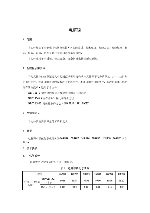
电解镍1范围本文件规定了电解镍(包括电积镍)产品的分类、技术要求、检验方法、检验规则、标志、包装、运输、贮存及随行文件和订货单等内容。
本文件适用于不锈钢、镍基合金、合金钢及电镀等用电解镍。
2规范性引用文件下列文件中的内容通过文中的规范性引用而构成本文件必不可少的条款。
其中,注日期的引用文件,仅该日期对应的版本适用于本文件;不注日期的引用文件,其最新版本(包括所有的修改单)适用于本文件。
GB/T8170数值修约规则与极限数值的表示和判定GB/T8647(所有部分)镍化学分析方法GB/T26022精炼镍取样方法(ISO7156:1991,MOD)3术语和定义本文件没有需要界定的术语和定义。
4分类电解镍产品按化学成分分为Ni9999、Ni9997、Ni9996、Ni9990、Ni9950、Ni9920六个牌号。
5技术要求5.1化学成分电解镍的化学成分应符合表1的规定。
表1电解镍的化学成分5.2外观质量5.2.1产品表面及夹层应洁净,无污泥、油污、电解液等。
注:Ni9950、Ni9920牌号可为不定形电解镍产品。
5.2.2Ni9999、Ni9997、Ni9996、Ni9990牌号电解镍应符合以下规定。
5.2.2.1产品平均厚度不应小于3mm。
5.2.2.2产品边缘不应有树枝状结粒及密集气孔(允许修整)。
5.2.2.3产品表面不应有直径大于3mm的密集气孔,直径3mm密集气孔区总面积不得超过镍板单面面积的15%。
5.2.2.4产品表面高度大于3mm的密集结粒区总面积不应超过镍板单面积15%。
注:25mm×25mm镍板面积上有9个以上气孔或结粒称为密集气孔区或密集结粒区。
5.3其他要求需方如对产品化学成分、物理规格有特殊要求,可由供需双方协商确定并在订货单中注明。
6试验方法6.1产品化学成分的测定按照GB/T8647的规定进行。
6.2产品的外观质量由目视检查。
7检验规则7.1检查与验收7.1.1产品由供方或第三方检验,产品质量应符合本文件及订货单的规定。
无取向硅钢牌号分类及化学成分

无取向硅钢牌号分类及化学成分
关于无取向硅钢牌号的分类及其化学成分,以下是一个常见的分类和化学成分简介:
1. 无取向硅钢牌号分类:
- 35W300:表示硅钢中的Si含量为3%,W表示无取向(无
方向性)。
牌号后面的数字300表示粘结剂的铁损(铁心损耗)为3.0W/kg。
- 50W350:表示硅钢中的Si含量为5%,W表示无取向。
牌
号后面的数字350表示粘结剂的铁损为3.5W/kg。
- 50W470:表示硅钢中的Si含量为5%,W表示无取向。
牌
号后面的数字470表示粘结剂的铁损为4.7W/kg。
2. 无取向硅钢化学成分:
无取向硅钢的化学成分主要由铁(Fe)和硅(Si)组成,其他
元素如碳(C)、锰(Mn)、硫(S)和磷(P)等通常以微
量的形式存在。
硅钢中的硅元素起到抑制铁磁晶格的形成,从而降低铁心损耗的作用。
具体的化学成分会因不同牌号而有所差异。
需要注意的是,以上内容仅为常见情况的简介,实际情况可能因不同国家、不同标准而有所不同。
为了得到准确的信息,建议查阅相关的硅钢牌号标准或咨询相关专业人士。
- 1、下载文档前请自行甄别文档内容的完整性,平台不提供额外的编辑、内容补充、找答案等附加服务。
- 2、"仅部分预览"的文档,不可在线预览部分如存在完整性等问题,可反馈申请退款(可完整预览的文档不适用该条件!)。
- 3、如文档侵犯您的权益,请联系客服反馈,我们会尽快为您处理(人工客服工作时间:9:00-18:30)。
Confidential Rev. 1.3 9/08Copyright © 2008 by Silicon LaboratoriesSi4708/09-BThis information applies to a product under development. Its characteristics and specifications are subject to change without notice.Silicon Laboratories Confidential. Information contained herein is covered under non-disclosure agreement (NDA).Si4708/09-BB ROADCAST FM R ADIO T UNER FOR P ORTABLE A PPLICATIONSSi4708/09-B2Confidential Rev. 1.3Si4708/09-BConfidential Rev. 1.33T ABLE OF C ONTENTSSectionPage1. Electrical Specifications. . . . . . . . . . . . . . . . . . . . . . . . . . . . . . . . . . . . . . . . . . . . . . . . . . . .42. Typical Application Schematic . . . . . . . . . . . . . . . . . . . . . . . . . . . . . . . . . . . . . . . . . . . . .123. Bill of Materials . . . . . . . . . . . . . . . . . . . . . . . . . . . . . . . . . . . . . . . . . . . . . . . . . . . . . . . . . .124. Functional Description . . . . . . . . . . . . . . . . . . . . . . . . . . . . . . . . . . . . . . . . . . . . . . . . . . .134.1. Overview . . . . . . . . . . . . . . . . . . . . . . . . . . . . . . . . . . . . . . . . . . . . . . . . . . . . . . . . . .134.2. FM Receiver . . . . . . . . . . . . . . . . . . . . . . . . . . . . . . . . . . . . . . . . . . . . . . . . . . . . . . .134.3. General Purpose Output . . . . . . . . . . . . . . . . . . . . . . . . . . . . . . . . . . . . . . . . . . . . . .144.4. RDS/RBDS Processor andFunctionality . . . . . . . . . . . . . . . . . . . . . . . . . . . . . . . . . . . . . . . . . . . . . . . . . . . . . . . . . . . . . . .144.5. Stereo Audio Processing . . . . . . . . . . . . . . . . . . . . . . . . . . . . . . . . . . . . . . . . . . . . . .144.6. Tuning . . . . . . . . . . . . . . . . . . . . . . . . . . . . . . . . . . . . . . . . . . . . . . . . . . . . . . . . . . . .154.7. Reference Clock . . . . . . . . . . . . . . . . . . . . . . . . . . . . . . . . . . . . . . . . . . . . . . . . . . . .164.8. Control Interface . . . . . . . . . . . . . . . . . . . . . . . . . . . . . . . . . . . . . . . . . . . . . . . . . . . .164.9. Reset, Powerup, and Powerdown . . . . . . . . . . . . . . . . . . . . . . . . . . . . . . . . . . . . . . .164.10. Audio Output Summation . . . . . . . . . . . . . . . . . . . . . . . . . . . . . . . . . . . . . . . . . . . .174.11. Initialization Sequence . . . . . . . . . . . . . . . . . . . . . . . . . . . . . . . . . . . . . . . . . . . . . .174.12. Programming Guide . . . . . . . . . . . . . . . . . . . . . . . . . . . . . . . . . . . . . . . . . . . . . . . .185. Register Summary. . . . . . . . . . . . . . . . . . . . . . . . . . . . . . . . . . . . . . . . . . . . . . . . . . . . . . . .196. Register Descriptions. . . . . . . . . . . . . . . . . . . . . . . . . . . . . . . . . . . . . . . . . . . . . . . . . . . . .207. Pin Descriptions: Si4708/09-GM . . . . . . . . . . . . . . . . . . . . . . . . . . . . . . . . . . . . . . . . . . . .338. Ordering Guide . . . . . . . . . . . . . . . . . . . . . . . . . . . . . . . . . . . . . . . . . . . . . . . . . . . . . . . . . .349. Package Markings (Top Marks) . . . . . . . . . . . . . . . . . . . . . . . . . . . . . . . . . . . . . . . . . . . . .359.1. Si4708 Top Mark . . . . . . . . . . . . . . . . . . . . . . . . . . . . . . . . . . . . . . . . . . . . . . . . . . . .359.2. Si4709 Top Mark . . . . . . . . . . . . . . . . . . . . . . . . . . . . . . . . . . . . . . . . . . . . . . . . . . . .359.3. Top Mark Explanation . . . . . . . . . . . . . . . . . . . . . . . . . . . . . . . . . . . . . . . . . . . . . . . .3510. Package Outline: Si4708/09-GM. . . . . . . . . . . . . . . . . . . . . . . . . . . . . . . . . . . . . . . . . . . .3611. PCB Land Pattern: Si4708/09-GM . . . . . . . . . . . . . . . . . . . . . . . . . . . . . . . . . . . . . . . . . .3712. Additional Reference Resources. . . . . . . . . . . . . . . . . . . . . . . . . . . . . . . . . . . . . . . . . . .39Document Change List . . . . . . . . . . . . . . . . . . . . . . . . . . . . . . . . . . . . . . . . . . . . . . . . . . . . .40Contact Information . . . . . . . . . . . . . . . . . . . . . . . . . . . . . . . . . . . . . . . . . . . . . . . . . . . . . . . .42Si4708/09-B4Confidential Rev. 1.31. Electrical SpecificationsTable 1. Recommended Operating ConditionsParameter Symbol Test Condition Min Typ Max Unit Digital Supply Voltage V D 2.7— 5.5V Analog Supply Voltage V A 2.7— 5.5V Interface Supply Voltage V IO 1.5— 3.6V Ambient Temperature T A–202585°C Digital Power Supply Power-Up Rise Time V DRISE10——µs Analog Power Supply Power-Up Rise Time V ARISE10——µs Interface Power Supply Power-Up Rise Time V IRISE10——µs Note:All minimum and maximum specifications are guaranteed and apply across the recommended operating conditions.Typical values apply at V D = V A = 3.3V and 25°C unless otherwise stated. Parameters are tested in production unless otherwise stated.Table 2. Absolute Maximum Ratings1,2Parameter Symbol Value UnitDigital Supply Voltage V D –0.5 to 5.8VAnalog Supply Voltage V A–0.5 to 5.8VInterface Supply Voltage V IO–0.5 to 3.9VInput Current3I IN±10mAInput Voltage3V IN–0.3 to (V IO + 0.3)V Operating Temperature T OP–40 to 95°CStorage Temperature T STG–55 to 150°CRF Input Level40.4V pKNotes:1.Permanent device damage may occur if the above Absolute Maximum Ratings are exceeded. Functional operationshould be restricted to the conditions as specified in the operational sections of this data sheet. Exposure beyond recommended operating conditions for extended periods may affect device reliability.2. The Si4708/09 device is a high-performance RF integrated circuit with an ESD rating of < 2 kV HBM. Handling andassembly of this device should only be done at ESD-protected workstations.3. For input pins SCLK, SEN, SDIO, RST, RCLK, and GPO.4. At RF input pins.Si4708/09-BConfidential Rev. 1.35Table 3. DC Characteristics 1(V D = V A = 2.7 to 3.6V, V IO = 1.5 to 3.6V, T A = –20 to 85°C)ParameterSymbol Test Condition Min Typ Max Unit Analog Operating Supply Current 2I A ENABLE = 1—10.8—mA Digital Operating Supply Current 2I D ENABLE = 1— 3.3—mA Interface Operating Supply Current 2I IO ENABLE = 1—0.3—mA Total Operating Supply Current 2,3,4I OP ENABLE = 1—14.616.9mA Total Operating Supply Current 2,3,4,5I OP ENABLE = 1Low SNR signal —15.517.8mA Total Operating Supply Current 2,3,4,6I OP ENABLE = 1RDS =1—15.217.4mA Total Operating Supply Current 2,3,4,5,6I OPENABLE = 1RDS =1,Low SNR signal —16.017.8mAAnalog Powerdown Supply Current 2,7I APD ENABLE = 0— 3.5—µA Digital Powerdown Supply Current 2,7I DPD ENABLE = 0— 2.5—µA Interface Powerdown Supply Current 2,7I IOPD ENABLE =0SCLK, RCLK inactive— 2.5—µA Total Powerdown Supply Current 2,7I PD ENABLE =0—8.512.0µA High Level Input Voltage 8V IH 0.7x V IO —V IO +0.3V Low Level Input Voltage 8V IL –0.3—0.3x V IOV High Level Input Current 8I IH V IN = V IO = 3.6V –10—10µA Low Level Input Current 8I IL V IN = 0V, V IO = 3.6V –10—10µA High Level Output Voltage 9V OH I OUT = 500µA 0.8x V IO——V Low Level Output Voltage 9V OLI OUT = –500µA——0.2x V IOVNotes:1.All specifications for the Si4708 unless otherwise noted.2. Refer to Register 02h, "Power Configuration" on page 21 for ENABLE bit description.3. The LNA is automatically switched to higher current mode for optimum sensitivity in low SNR conditions.4. Analog and digital supply currents are simultaneously adjusted based on SNR level.5. Stereo and/or RDS functionality are disabled at low SNR levels.6. RDS functionality only available for Si4709.7. Refer to Section 4.9. "Reset, Powerup, and Powerdown" on page 16.8. For input pins SCLK, SEN, SDIO, RST, RCLK, and GPO.9. For output pins SDIO and GPO.Si4708/09-B6Confidential Rev. 1.3Table 4. Reset Timing Characteristics (Busmode Select Method)1,2(V DD = 2.7 to 5.5V, V IO = 1.5 to 3.6V, T A = –20 to 85 °C)Si4708/09-BConfidential Rev. 1.37Table 5. 3-Wire Control Interface Characteristics(V D = V A = 2.7 to 5.5V, V IO = 1.5 to 3.6V, T A = –20 to 85°C)Si4708/09-B8Confidential Rev. 1.3Table 6. 2-Wire Control Interface Characteristics1,2,3(V D = V A = 2.7 to 5.5V, V IO = 1.5 to 3.6V, T A = –20 to 85°C)Parameter Symbol Test Condition Min Typ Max Unit SCLK Frequency f SCL0—400kHzSCLK Low Time t LOW 1.3——µs SCLK High Time t HIGH0.6——µs SCLK Input to SDIO↓ Setup(START)t SU:STA0.6——µs SCLK Input to SDIO↓ Hold (START)t HD:STA0.6——µs SDIO Input to SCLK↑ Setup t SU:DAT100——ns SDIO Input to SCLK↓ Hold4,5t HD:DAT0—900ns SCLK input to SDIO↑ Setup (STOP)t SU:STO0.6——µs STOP to START Time t BUF 1.3——µs SDIO Output Fall Time t f:OUT20 + 0.1 C b—250ns SDIO Input, SCLK Rise/Fall Time t f:INt r:IN20 + 0.1 C b—300ns SCLK, SDIO Capacitive Loading C b——50pF Input Filter Pulse Suppression t SP——50nsNotes:1.When V IO=0V, SCLK and SDIO are low impedance.2. When selecting 2-wire mode, the user must ensure that SCLK is high during the rising edge of RST, and stays highuntil after the 1st start condition.3. When selecting 2-wire Mode, the user must ensure that a 2-wire start condition (falling edge of SDIO while SCLK ishigh) does not occur within 300ns before the rising edge of RST.4. As a 2-wire transmitter, the Si4708/09-B delays SDIO by a minimum of 300ns from the V IH threshold of SCLK tocomply with the 0ns t HD:DAT specification.5. The maximum t HD:DAT has only to be met when f SCL=400kHz. At frequencies below 400kHz, t HD:DAT may be violatedso long as all other timing parameters are met.Si4708/09-BConfidential Rev. 1.39Si4708/09-B10Confidential Rev. 1.3Table 7. FM Receiver Characteristics1,2(V D = V A = 2.7 to 5.5V, V IO = 1.5 to 3.6V, T A = –20 to 85°C)Parameter Symbol Test Condition Min Typ Max Unit Input Frequency f RF76—108MHz Sensitivity3,4,5,6,7(S+N)/N = 26 dB— 1.7 3.5µVEMF Sensitivity (50Ω matchingnetwork)3,4,5,6,8(S+N)/N = 26 dB— 1.1—µVEMFRDS Sensitivity8Δf = 2kHz,RDS BLER < 5%—15—µVEMF LNA Input Resistance8,9345kΩLNA Input Capacitance8,9456pF Input IP38,10104106—dBµVEMF AM Suppression3,4,5,8,9m = 0.34055—dB Adjacent Channel Selectivity±200 kHz3550—dB Alternate Channel Selectivity±400 kHz6070—dB Spurious Response Rejection8In-band35——dB RCLK Frequency—32.768—kHz RCLK Frequency Tolerance11SPACE[1:0]=00 or 01–200—200ppmSPACE[1:0]=10–50—50Audio Output Voltage3,4,5,9728090mV RMS Audio Output L/R Imbalance3,4,9,12——1dB Audio Frequency Response Low8–3dB——30Hz Audio Frequency Response High8–3dB15——kHz Audio Stereo Separation3,9,1225——dB Notes:1.Additional testing information is available in Application Note AN388. Volume=maximum for all tests.2. Important Note: To ensure proper operation and FM receiver performance, follow the guidelines in “AN350: Si4708/09Antenna, Schematic, Layout, and Design Guidelines.” Silicon Laboratories will evaluate schematics and layouts for qualified customers.3. F MOD=1kHz, 75 µs de-emphasis4. MONO=1, and L=R unless noted otherwise.5. Δf=22.5kHz.6. B AF=300Hz to 15kHz, A-weighted.7. Typical sensitivity with headphone matching network.8. Guaranteed by characterization.9. V EMF=1mV.10. |f2 – f1| > 1 MHz, f0=2x f1 – f2. AGC is disabled by setting AGCD=1. Refer to "6. Register Descriptions" on page20.11. The channel spacing is selected with the SPACE[1:0] bits. Refer to "6. Register Descriptions" on page 20. Seek/Tunetiming is guaranteed for 100 and 200kHz channel spacing. ±50ppm PCLK tolerance required for 50kHz channelspacing.12. Δf=75kHz.13. The de-emphasis time constant is selected with the DE bit. Refer to "6. Register Descriptions" on page 20.14. At LOUT and ROUT pins.15. Do not enable STC interrupts before the powerup time is complete. If STC interrupts are enabled before the poweruptime is complete, an interrupt will be generated within the powerup interval when the initial default tune operation is complete. See "AN349: Si4708/09 Programming Guide" for more information.16. Minimum and maximum at room temperature (25°C).Si4708/09-BMono/Stereo Switching Level3,8,12BLNDADJ=1010dB stereo separation—34—dBµVEMFAudio Mono S/N3,4,5,6,95560—dB Audio Stereo S/N3,5,6,8BLNDADJ=10—58—dB Audio THD3,4,9,12—0.10.5% De-emphasis Time Constant13DE=0707580µsDE=1455054µs Audio Common Mode Voltage14ENABLE=10.650.80.9VAudio Common Mode Voltage14ENABLE=0AHIZEN=1—0.5x V IO—VAudio Output Load Resistance8,14R L Single-ended10——kΩAudio Output Load Capacitance8,14C L Single-ended——50pFSeek/Tune Time8,11SPACE[1:0]=0x,RCLKtolerance=200ppm,(x=0 or 1)——60ms/channelPowerup Time15From powerdown(Write ENABLE bit to 1)——110msRSSI Offset16Input levels of 8 and60dBµV at RF input –3—3dBTable 7. FM Receiver Characteristics1,2 (Continued)(V D = V A = 2.7 to 5.5V, V IO = 1.5 to 3.6V, T A = –20 to 85°C)Parameter Symbol Test Condition Min Typ Max Unit Notes:1.Additional testing information is available in Application Note AN388. Volume=maximum for all tests.2. Important Note: To ensure proper operation and FM receiver performance, follow the guidelines in “AN350: Si4708/09Antenna, Schematic, Layout, and Design Guidelines.” Silicon Laboratories will evaluate schematics and layouts for qualified customers.3. F MOD=1kHz, 75 µs de-emphasis4. MONO=1, and L=R unless noted otherwise.5. Δf=22.5kHz.6. B AF=300Hz to 15kHz, A-weighted.7. Typical sensitivity with headphone matching network.8. Guaranteed by characterization.9. V EMF=1mV.10. |f2 – f1| > 1 MHz, f0=2x f1 – f2. AGC is disabled by setting AGCD=1. Refer to "6. Register Descriptions" on page20.11. The channel spacing is selected with the SPACE[1:0] bits. Refer to "6. Register Descriptions" on page 20. Seek/Tunetiming is guaranteed for 100 and 200kHz channel spacing. ±50ppm PCLK tolerance required for 50kHz channelspacing.12. Δf=75kHz.13. The de-emphasis time constant is selected with the DE bit. Refer to "6. Register Descriptions" on page 20.14. At LOUT and ROUT pins.15. Do not enable STC interrupts before the powerup time is complete. If STC interrupts are enabled before the poweruptime is complete, an interrupt will be generated within the powerup interval when the initial default tune operation is complete. See "AN349: Si4708/09 Programming Guide" for more information.16. Minimum and maximum at room temperature (25°C).Si4708/09-B2. Typical Application Schematic7. Place Si4708/09 as close as possible to antenna jack and keep the FMI trace as short as possible.8. V A and V D may be supplied from the same V BAT or may be supplied by independent power supplies.9. Place R1 on the opposite side of the PCB as the tuner (as close to pin 15 as possible), and route the GPO trace to thesystem controller on this layer.3. Bill of MaterialsComponent(s)Value/Description Supplier(s)C1Supply bypass capacitor, 22nF, ±20%, Z5U/X7R MurataR1GPO resistor, 1kΩVenkelU1Si4708/09 FM Radio Tuner Silicon LaboratoriesSi4708/09-B 4. Functional Description6.25mm2capacitor.to the subjective nature of FM listeners’ audio preferences and variable FM broadcast environments worldwide.The Si4709 incorporates a digital processor for the European Radio Data System (RDS) and the US Radio Broadcast Data System (RBDS) including all required symbol decoding, block synchronization, error detection, and error correction functions.RDS/RDBS* enables data such as station identification and song name to be displayed to the user. The Si4709 offers a detailed RDS view and a standard view, allowing adopters to selectively choose granularity ofA.remainder of this document.4.2. FM ReceiverThe Si4708/09 architecture and antenna design increases system performance. To ensure proper performance and operation, designers should refer to the guidelines in "AN350: Si4708/09 Antenna, Schematic, Layout, and Design Guidelines". Conformance to these guidelines will help to ensure excellent performance in weak signal, noisy, and crowded signal environments where many strong channels are present.Si4708/09-BThe Si4708/09’s patented digital low-IF architecture reduces external components and eliminates the need for factory adjustments. The receive (RX) section integrates a low noise amplifier (LNA) supporting the worldwide FM broadcast band (76 to 108MHz). An automatic gain control (AGC) circuit controls the gain of the LNA to optimize sensitivity and rejection of strong interferers.An image-reject mixer downconverts the RF signal to low-IF. The quadrature mixer output is amplified,filtered, and digitized with high resolution analog-to-digital converters (ADCs). This advanced architecture achieves superior performance by usingarchitectures.and V D block-error levels and synchronization status with verbose mode.Setting the RDS mode (RDSM) bit low places the device in standard RDS mode (default). The device will set the RDS ready (RDSR) bit for a minimum of 40ms when a valid RDS group has been received. Setting the RDS interrupt enable (RDSIEN) bit and GPO[1:0] = 01will configure GPO to pulse low for a minimum of 5ms when a valid RDS group has been received. If an invalid group is received, RDSR will not be set and GPO will not pulse low. In standard mode RDS synchronization (RDSS) and block error rate A, B, C and D (BLERA,BLERB, BLERC, and BLERD) are unused and will read 0. This mode is backward compatible with earlier firmware revisions.Setting the RDS mode bit high places the device in RDS verbose mode. The device sets RDSS high when synchronized and low when synchronization is lost. If the device is synchronized, RDS ready (RDSR) will be set for a minimum of 40ms when a RDS group has been received. Setting the RDS interrupt enable (RDSIEN) bit and GPO[1:0] = 01 will configure GPO to pulse low for a minimum of 5ms if the device is synchronized and an RDS group has been received.BLERA, BLERB, BLERC and BLERD provide The Si4708/09's integrated stereo decoder automatically decodes the MPX signal. The 0 to 15 kHz (L+R) signal is the mono output of the FM tuner. Stereo is generated from the (L+R), (L-R), and a 19 kHz pilot tone. The pilot tone is used as a reference to recover the (L-R) signal. Separate left and right channels are obtained by adding and subtracting the (L+R) and (L-R)signals, respectively. The Si4709 uses frequency information from the 19kHz stereo pilot to recover the 57kHz RDS/RBDS signal.Adaptive noise suppression is employed to gradually combine the stereo left and right audio channels to a mono (L+R) audio signal as the signal quality degradesSi4708/09-Bto maintain optimum sound fidelity under varying reception conditions. The signal level range over which the stereo to mono blending occurs can be adjusted by setting the BLNDADJ[1:0] register. Stereo/mono status can be monitored with the ST register bit and mono operation can be forced with the MONO register bit. Pre-emphasis and de-emphasis is a technique used by FM broadcasters to improve the signal-to-noise ratio of FM receivers by reducing the effects of high frequency interference and noise. When the FM signal is transmitted, a pre-emphasis filter is applied to accentuate the high audio frequencies. All FM receivers incorporate a de-emphasis filter which attenuates high frequencies to restore a flat frequency response. Two time constants, 50 or 75µs, are used in various regions. The de-emphasis time constant is programmable with the DE bit.High-fidelity stereo digital-to-analog converters (DACs) drive analog audio signals onto the LOUT and ROUT pins. The audio output may be muted with the DMUTE bit. Volume can be adjusted digitally with the VOLUME[3:0] bits. The volume dynamic range can be set to either –28dBFS (default) or –58dBFS by setting VOLEXT=1.The soft mute feature is available to attenuate the audio outputs and minimize audible noise in very weak signal conditions. The soft mute attack and decay rate can be adjusted with the SMUTER[1:0] bits where 00 is the fastest setting. The soft mute attenuation level can be adjusted with the SMUTEA[1:0] bits where 00 is the most attenuated. The soft mute disable (DSMUTE) bit may be set high to disable this feature.4.6. TuningThe Si4708/09 uses Silicon Laboratories’ patented and proven frequency synthesizer technology including a completely integrated VCO. The frequency synthesizer generates the quadrature local oscillator signal used to downconvert the RF input to a low intermediate frequency. The VCO frequency is locked to the reference clock and adjusted with an automatic frequency control (AFC) servo loop during reception. The tuning frequency is defined as:Channel spacing of 50, 100 or 200 KHz is selected with bits SPACE[1:0]. The channel is selected with bits CHAN[9:0]. The bottom of the band is set to 76 MHz or 87.5 MHz with the bits BAND[1:0]. The tuning operation begins by setting the TUNE bit. After tuning completes, the seek/tune complete (STC) bit will be set and the RSSI level is available by reading bits RSSI[7:0]. The TUNE bit must be set low after the STC bit is set high in order to complete the tune operation and clear the STC bit.Seek tuning searches up or down for a channel with an RSSI greater than or equal to the seek threshold set with the SEEKTH[7:0] bits. In addition, an optional SNR and/or impulse noise detector may be used to qualify valid stations. The SKSNR[3:0] bits set the SNR threshold required. The SKCNT[3:0] bits set the impulse noise threshold. Using the extra seek qualifiers can reduce false stops and, in combination with lowering the RSSI seek threshold, increase the number of found stations. The SNR and impulse noise detectors are disabled by default.Two seek modes are available. When the seek mode (SKMODE) bit is low and a seek is initiated, the device seeks through the band, wraps from one band edge to the other, and continues seeking. If the seek operation was unable to find a channel, the seek failure/band limit (SF/BL) bit will be set high and the device will return to the channel selected before the seek operation began. When the SKMODE bit is high and a seek is initiated, the device seeks through the band until the band limit is reached and the SF/BL bit will be set high. A seek operation is initiated by setting the SEEK and SEEKUP bits. After the seek operation completes, the STC bit will be set, and the RSSI level and tuned channel are available by reading bits RSSI[7:0] and bits READCHAN[9:0]. During a seek operation READCHAN[9:0] is also updated and may be read to determine seek progress. The STC bit will be set after the seek operation completes. The channel is valid if the seek operation completes and the SF/BL bit is set low. At other times, such as before a seek operation or after a seek completes and the SF/BL bit is set high, the channel is valid if the AFC Rail (AFCRL) bit is set low and the value of RSSI[7:0] is greater than or equal to SEEKTH[7:0]. Note that if the AFCRL bit is set, the audio output is muted as in the softmute case discussed in Section “4.5. Stereo Audio Processing”. The SEEK bit must be set low after the STC bit is set high in order to complete the seek operation and clear the STC and SF/BL bits. The seek operation may be aborted by setting the SEEK bit low at any time.The device can be configured to generate an interrupt on GPO when a tune or seek operation completes. Setting the seek/tune complete (STCIEN) bit and GPO[1:0]=01 will configure GPO for a 5ms low interrupt when the STC bit is set by the device.For additional recommendations on optimizing the seek function, consult "AN349: Si4708/09 Programming Guide."Freq (MHz)Spacing (kHz)Channel Bottom of Band (MHz)+×=Si4708/09-B4.7. Reference ClockThe Si4708/09-B accepts a 32.768kHz reference clock to the RCLK pin. The reference clock is required whenever the ENABLE bit is set high. Refer to Table3,“DC Characteristics1,” on page5 for input switching voltage levels and Table7, "FM Receiver Characteristics," on page10 for frequency tolerance information.4.8. Control InterfaceTwo-wire slave-transceiver and three-wire interfaces are provided for the controller IC to read and write the control registers. Refer to “4.9. Reset, Powerup, and Powerdown” for a description of bus mode selection. Registers may be written and read when the V IO supply is applied regardless of the state of the V D or V A supplies. RCLK is not required for proper register operation.4.8.1. 3-Wire Control InterfaceFor three-wire operation, a transfer begins when the SEN pin is sampled low by the device on a rising SCLK edge. The control word is latched internally on rising SCLK edges and is nine bits in length, comprised of a four bit chip address A7:A4 = 0110b, a read/write bit (write = 0 and read = 1), and a four bit register address, A3:A0. The ordering of the control word is A7:A5, R/W, A4:A0. Refer to Section 5. "Register Summary" on page 19 for a list of all registers and their addresses.For write operations, the serial control word is followed by a 16-bit data word and is latched internally on rising SCLK edges.For read operations, a bus turn-around of half a cycle is followed by a 16-bit data word shifted out on rising SCLK edges and is clocked into the system controller on falling SCLK edges. The transfer ends on the rising SCLK edge after SEN is set high. Note that 26 SCLK cycles are required for a transfer, however, SCLK may run continuously.For details on timing specifications and diagrams, refer to Table5, “3-Wire Control Interface Characteristics,” on page7, Figure2, “3-Wire Control Interface Write Timing Parameters,” on page 7, and Figure3, “3-Wire Control Interface Read Timing Parameters,” on page 7.4.8.2. 2-Wire Control InterfaceFor two-wire operation, the SCLK and SDIO pins function in open-drain mode (pull-down only) and must be pulled up by an external device. A transfer begins with the START condition (falling edge of SDIO while SCLK is high). The control word is latched internally on rising SCLK edges and is eight bits in length, comprised of a seven bit device address equal to 0010000b and a read/write bit (write = 0 and read = 1).The device acknowledges the address by driving SDIO low after the next falling SCLK edge, for 1 cycle. For write operations, the device acknowledge is followed by an eight bit data word latched internally on rising edges of SCLK. The device acknowledges each byte of data written by driving SDIO low after the next falling SCLK edge, for 1 cycle. An internal address counter automatically increments to allow continuous data byte writes, starting with the upper byte of register 02h, followed by the lower byte of register 02h, and onward until the lower byte of the last register is reached. The internal address counter then automatically wraps around to the upper byte of register 00h and proceeds from there until continuous writes end. Data transfer ends with the STOP condition (rising edge of SDIO while SCLK is high). After every STOP condition, the internal address counter is reset.For read operations, the device acknowledge is followed by an eight bit data word shifted out on falling SCLK edges. An internal address counter automatically increments to allow continuous data byte reads, starting with the upper byte of register 0Ah, followed by the lower byte of register 0Ah, and onward until the lower byte of the last register is reached. The internal address counter then automatically wraps around to the upper byte of register 00h and proceeds from there until continuous reads cease. After each byte of data is read, the controller IC must drive an acknowledge (SDIO=0) if an additional byte of data will be requested. Data transfer ends with the STOP condition. After every STOP condition, the internal address counter is reset. For details on timing specifications and diagrams, refer to Table6, “2-Wire Control Interface Characteristics1,2,3,” on page8, Figure4, “2-Wire Control Interface Read and Write Timing Parameters,”on page 9 and Figure5, “2-Wire Control Interface Read and Write Timing Diagram,” on page 9.4.9. Reset, Powerup, and Powerdown Driving the RST pin low will disable the Si4708/09 and its control bus interface, and reset the registers to their default settings. Driving the RST pin high will bring the device out of reset. As the part is brought out of reset, the SEN pin is used to select between 2-wire and 3-wire control interface operation.。