LM4050AEM3-5.0-T中文资料
505中文使用说明书(上册)

监视计时器 第三章
CPU 故 障 控 制 ..................................... 2-11
安装步骤 ..................................................... 3-1 机 械 数 据 与 硬 件 的 安 装 ......................................... 3-1 壳体 ..................................................... 3-1 安装 ..................................................... 3-5 505 的跨 接 件 ............................................. 3-5 电气 连 接 ................................................. 3-7 电源 .................................................... 3-11 屏蔽 与 接 地 .............................................. 3-12 转速 传 感 器 的 输 入 ........................................ 3-13 触点 输 入 ................................................ 3-14 模拟 输 入 ................................................ 3-15 模拟 输 出 ................................................ 3-15 执行 机 构 输 出 ............................................ 3-16 继电 器 输 出 .............................................. 3-16 串行 通 信 ................................................ 3-17 Modbus 接线 ............................................. 3-17 RS-232 接线 .......................................... 3-17 RS-422 接线 .......................................... 3-18 RS-485 接线 .......................................... 3-18 通 信 的 接 地 与 屏 蔽 ............................................ 3-19 第四章 505 的控制说明 ............................................... 4-1 汽 轮 机 起 动 ................................................... 4-1 允许 起 动 ................................................. 4-2 零 转 速 信 号 超 越 ............................................... 4-2 手动 转 速 超 越 ............................................. 4-2 自动 转 速 超 越 ............................................. 4-3 汽 轮 机 起 动 方 式 ............................................... 4-3 手动 起 动 方 式 ............................................. 4-3 半自 动 起 动 方 式 ........................................... 4-4 自动 起 动 方 式 ............................................. 4-4 避 开 临 界 转 速 ................................................. 4-5 暖机 额 定 ................................................... 4-6 至额 定 转 速 的 特 性 ......................................... 4-6
北京捷麦通信器材有限公司 R4050 开关量模块用户手册说明书
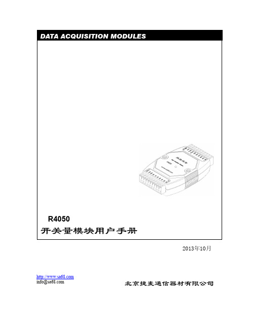
2013年10月北京捷麦通信器材有限公司R4050开关量模块用户手册 DATA ACQUISITION MODULES *************目录1概述 (3)1.1 特点 (3)1.2 外观和安装 (3)1.3 技术指标 (4)1.4指示灯状态 (4)2 电路连接 (5)2.1 输入电路连接 (5)2.2 输出电路连接 (6)2.3 通信电路的连接 (7)2.4 模块的输出值 (7)3 通用指令和模块的基本设置 (7)3.1 指令的基本格式 (7)3.2 设置模块配置-%AANNTTCCFF (9)3.3读配置信息-$AA2 (10)3.4读版本信息-$AAF (10)3.5 读复位状态-$AA5 (11)3.6 读模块名-$AAM (11)3.7写模块名-~AAO(数据) (12)4 采集和输出指令 (13)4.1同步采样-#** (13)4.2读同步数据-$AA4 (14)4.3数字输出-#AABBDD (14)4.4设置数字输出-@AA(数据) (15)4.5读数字输出/输入状态-$AA6 (16)4.6读数字输入/输出状态-@AA (16)4.7 读锁存状态-$AALS (17)4.8 清除锁存状态-$AAC (18)4.9 读入计数值-#AAN (19)4.10 清计数器-$AACN (19)5 遥控和报警指令及应用 (20)5.1 模式 (20)5.2读模块模式-#AAM (22)5.3设置模块模式-#AAMAB (23)5.4 读遥控目的地址-#AAR (24)5.5写遥控目的地址-#AAR(数据) (24)5.6读重发间隔时间-#AAT (25)5.7设置重发间隔时间-#AATDD (25)6 看门狗的使用和指令 (26)6.1 ~** (26)6.2 ~AA0 (27)6.3 ~AA1 (27)6.4~AA2 (28)6.5 ~AA3EVV (28)6.6 ~AA4V (29)6.7 ~AA5V (30)————————————————————————————————————————————————附件1:ASCII码对照表 (31)————————————————————————————————————————————————1概述1.1 特点R4050模块是R4000系列采集模块中的开关量输入输出模块,具有7路电压开关量输入,8路晶体管集电极开路输出。
广州致远电子有限公 RSM-4050 非隔离数字量输入输出模块 产品说明书
广州致远电子有限公司类别内容关键词 RSM-4050数字量输入输出数据采集摘要 RSM-4050使用指南修订历史版本日期原因VX1 2008/04/09 创建文档V1.00 2008/05/07 第一次发布V1.01 2008/07/10 特别注意,不允许热插拔接线端子V1.02 2008/12/17 I/O资源及通信协议说明销售与服务网络(一)广州周立功单片机发展有限公司地址:广州市天河北路689号光大银行大厦12楼F4 邮编:510630电话:(020)38730916 38730917 38730972 38730976 38730977传真:(020)38730925网址:广州专卖店地址:广州市天河区新赛格电子城203-204室电话:(020)87578634 87569917传真:(020)87578842 南京周立功地址:南京市珠江路280号珠江大厦2006室电话:(025)83613221 83613271 83603500 传真:(025)83613271北京周立功地址:北京市海淀区知春路113号银网中心A座1207-1208室(中发电子市场斜对面)电话:(010)62536178 62536179 82628073传真:(010)82614433 重庆周立功地址:重庆市石桥铺科园一路二号大西洋国际大厦(赛格电子市场)1611室电话:(023)68796438 68796439传真:(023)68796439杭州周立功地址:杭州市天目山路217号江南电子大厦502室电话:(0571) 28139611 28139612 28139613传真:(0571) 28139621 成都周立功地址:成都市一环路南二段1号数码同人港401室(磨子桥立交西北角)电话:(028)85439836 85437446传真:(028)85437896深圳周立功地址:深圳市深南中路 2070号电子科技大厦C座4楼D室电话:(0755)83781788(5线)传真:(0755)83793285 武汉周立功地址:武汉市洪山区广埠屯珞瑜路158号12128室(华中电脑数码市场)电话:(027)87168497 87168297 87168397传真:(027)87163755上海周立功地址:上海市北京东路668号科技京城东座7E室电话:(021)53083452 53083453 53083496传真:(021)53083491 西安办事处地址:西安市长安北路54号太平洋大厦1201室电话:(029)87881296 83063000 87881295传真:(029)87880865销售与服务网络(二)广州致远电子有限公司地址:广州市天河区车陂路黄洲工业区3栋2楼邮编:510660传真:(020)38601859网址:(嵌入式系统事业部)(工控网络事业部)(楼宇自动化事业部)技术支持:CAN-bus:电话:(020)22644381 22644382 22644253 邮箱:****************************iCAN及模块:电话:(020)28872344 22644373 邮箱:*********************MiniARM:电话:(020)28872684 28267813邮箱:******************************以太网及无线:电话:(020)22644380 22644385 22644386 邮箱:**********************************************************编程器:电话:(020)22644371邮箱:*************************分析仪器:电话:(020)22644375 28872624 28872345 邮箱:********************ARM嵌入式系统:电话:(020)28872347 28872377 22644383 22644384 邮箱:**********************楼宇自动化:电话:(020)22644376 22644389 28267806 邮箱:*************************************************销售:电话:(020)22644249 22644399 22644372 22644261 28872524 28872342 28872349 28872569 28872573 38601786维修:电话:(020)22644245目录1. RSM-4050功能简介 (1)1.1 主要技术指标 (2)1.1.1 数字量输入 (2)1.1.2 数字量输出 (2)1.1.3 系统参数 (2)1.2 原理框图 (3)1.3 端子信息 (4)1.3.1 端子排列 (4)1.3.2 端子描述 (4)1.4 电气参数 (5)1.5 通信参数设置 (5)1.6 信号指示灯 (5)1.6.1 固件升级状态 (6)1.6.2 正常运行状态 (6)1.7 电源和通讯线的连接 (6)1.8 机械规格 (7)1.8.1 机械尺寸 (7)1.8.2 安装方式 (7)2. RSM-4050的数字量输入输出功能 (9)2.1 数字量输入 (9)2.2 数字量输出 (9)2.2.1 输出原理 (9)2.2.2 输出接线方式 (10)2.2.3 数字量输出通道控制 (10)2.2.4 屏蔽同步输出 (10)2.2.5 输入匹配固定输出 (11)3. RSM-4050应用示例 (12)3.1 安装设备 (12)3.2 操作设备 (12)3.2.1 RS-485主机通信参数设置 (12)3.2.2 RSM系列模块通信参数的修改 (14)3.2.3 搜索设备 (14)3.2.4 模块信息配置 (15)3.2.5 功能操作 (16)3.2.6 固件升级 (18)3.2.7 串口终端测试 (19)4. RSM-4050资源地址及通信协议 (21)4.1 RSM系列模块资源地址 (21)4.1.1 RSM-4050的I/O端口资源 (21)4.1.2 配置资源 (22)4.2 通信协议 (22)4.2.1 MODBUS协议 (22)4.2.2 自定义ASCII协议命令简析 (23)5. 免责声明 (28)1. RSM-4050功能简介RSM-4050是数字量非隔离输入输出模块,可以同时采样8路数字量信号,支持开关触点信号和电平信号,同时具有8路数字量开漏输出。
英飞凌 FF450R33T3E3_B5 XHP 3 模块 数据表

XHP ™3 模块 采用第三代沟槽栅/场终止IGBT3和第三代发射极控制二极管特性•电气特性-V CES = 3300 V-I C nom = 450 A / I CRM = 900 A -高直流电压稳定性-高短路能力-低开关损耗-低 V CEsat-T vj op = 150°C -无与伦比的坚固性•机械特性-碳化硅铝 (AlSiC) 基板提供更高的温度循环能力-绝缘的基板-封装的 CTI > 600-加强绝缘封装,10.4kV 交流 60 秒可选应用•牵引变流器•中压变流器•电机传动产品认证•根据 IEC 60747、60749 和 60068标准的相关测试,符合工业应用的要求。
描述FF450R33T3E3_B5XHP ™3 模块内容描述 . . . . . . . . . . . . . . . . . . . . . . . . . . . . . . . . . . . . . . . . . . . . . . . . . . . . . . . . . . . . . . . . . . . . . . . . . . . . . . . . . . . . . . . . .1特性 . . . . . . . . . . . . . . . . . . . . . . . . . . . . . . . . . . . . . . . . . . . . . . . . . . . . . . . . . . . . . . . . . . . . . . . . . . . . . . . . . . . . . . . . .1可选应用 . . . . . . . . . . . . . . . . . . . . . . . . . . . . . . . . . . . . . . . . . . . . . . . . . . . . . . . . . . . . . . . . . . . . . . . . . . . . . . . . . . . .1产品认证 . . . . . . . . . . . . . . . . . . . . . . . . . . . . . . . . . . . . . . . . . . . . . . . . . . . . . . . . . . . . . . . . . . . . . . . . . . . . . . . . . . . .1内容 . . . . . . . . . . . . . . . . . . . . . . . . . . . . . . . . . . . . . . . . . . . . . . . . . . . . . . . . . . . . . . . . . . . . . . . . . . . . . . . . . . . . . . . . .2 1封装 . . . . . . . . . . . . . . . . . . . . . . . . . . . . . . . . . . . . . . . . . . . . . . . . . . . . . . . . . . . . . . . . . . . . . . . . . . . . . . . . . . . . . . . . .3 2IGBT, 逆变器 . . . . . . . . . . . . . . . . . . . . . . . . . . . . . . . . . . . . . . . . . . . . . . . . . . . . . . . . . . . . . . . . . . . . . . . . . . . . . . . . .3 3二极管,逆变器 . . . . . . . . . . . . . . . . . . . . . . . . . . . . . . . . . . . . . . . . . . . . . . . . . . . . . . . . . . . . . . . . . . . . . . . . . . . . . . .5 4特征参数图表 . . . . . . . . . . . . . . . . . . . . . . . . . . . . . . . . . . . . . . . . . . . . . . . . . . . . . . . . . . . . . . . . . . . . . . . . . . . . . . . .7 5电路拓扑图 . . . . . . . . . . . . . . . . . . . . . . . . . . . . . . . . . . . . . . . . . . . . . . . . . . . . . . . . . . . . . . . . . . . . . . . . . . . . . . . . .11 6封装尺寸 . . . . . . . . . . . . . . . . . . . . . . . . . . . . . . . . . . . . . . . . . . . . . . . . . . . . . . . . . . . . . . . . . . . . . . . . . . . . . . . . . . .12 7模块标签代码 . . . . . . . . . . . . . . . . . . . . . . . . . . . . . . . . . . . . . . . . . . . . . . . . . . . . . . . . . . . . . . . . . . . . . . . . . . . . . . .13修订历史 . . . . . . . . . . . . . . . . . . . . . . . . . . . . . . . . . . . . . . . . . . . . . . . . . . . . . . . . . . . . . . . . . . . . . . . . . . . . . . . . . . .14免责声明 . . . . . . . . . . . . . . . . . . . . . . . . . . . . . . . . . . . . . . . . . . . . . . . . . . . . . . . . . . . . . . . . . . . . . . . . . . . . . . . . . . .151封装表 1绝缘参数特征参数代号标注或测试条件数值单位绝缘测试电压V ISOL RMS, f = 50 Hz, t = 60 s10.4kV 局部放电熄弧电压V isol RMS, f = 50 Hz, Q PD typ. 10 pC 5.1kV 模块基板材料AlSiC爬电距离d Creep端子至散热器53.0mm 爬电距离d Creep端子至端子53.0mm 电气间隙d Clear端子至散热器36.0mm 电气间隙d Clear端子至端子26.0mm 相对电痕指数CTI > 600表 2特征值特征参数代号标注或测试条件数值单位最小值典型值最大值杂散电感,模块L sCE25nH 模块引线电阻,端子-芯片R AA'+CC'T C=25°C, 每个开关0.31mΩ模块引线电阻,端子-芯片R CC'+EE'T C=25°C, 每个开关0.41mΩ储存温度T stg-40150°C 模块安装的安装扭距M根据相应的应用手册进行安装M6, 螺丝 4.25 5.75Nm端子安装扭矩M根据相应的应用手册进行安装M3, 螺丝0.9 1.1Nm M8, 螺丝810重量G700g 2IGBT, 逆变器表 3最大标定值特征参数代号标注或测试条件数值单位集电极-发射极电压V CES T vj = -40 °C3300VT vj = 150 °C3300连续集电极直流电流I CDC T vj max = 150 °C T C = 100 °C450A 集电极重复峰值电流I CRM t p受限于 T vj op900A 栅极-发射极峰值电压V GES±20V表 4特征值特征参数代号标注或测试条件数值单位最小值典型值最大值集电极-发射极饱和电压V CE sat I C = 450 A, V GE = 15 V T vj = 25 °C 2.50 2.75VT vj = 125 °C 2.90T vj = 150 °C 3.00 3.30栅极阈值电压V GEth I C = 12 mA, V CE = V GE, T vj = 25 °C 5.20 5.80 6.40V 栅极电荷Q G V GE = ±15 V, V CE = 1800 V12.5µC 内部栅极电阻R Gint T vj = 25 °C 1.3Ω输入电容C ies f = 1000 kHz, T vj = 25 °C, V CE = 25 V, V GE = 0 V84nF 反向传输电容C res f = 1000 kHz, T vj = 25 °C, V CE = 25 V, V GE = 0 V2nF 集电极-发射极截止电流I CES V CE = 3300 V, V GE = 0 V T vj = 25 °C5mA 栅极-发射极漏电流I GES V CE = 0 V, V GE = 20 V, T vj = 25 °C400nA开通延迟时间(感性负载)t don I C = 450 A, V CE = 1800 V,V GE = ±15 V, R Gon = 0.7 ΩT vj = 25 °C0.530µs T vj = 125 °C0.570T vj = 150 °C0.580上升时间(感性负载)t r I C = 450 A, V CE = 1800 V,V GE = ±15 V, R Gon = 0.7 ΩT vj = 25 °C0.100µs T vj = 125 °C0.130T vj = 150 °C0.130关断延迟时间(感性负载)t doff I C = 450 A, V CE = 1800 V,V GE = ±15 V, R Goff = 3.3 ΩT vj = 25 °C 1.710µs T vj = 125 °C 1.860T vj = 150 °C 1.920下降时间(感性负载)t f I C = 450 A, V CE = 1800 V,V GE = ±15 V, R Goff = 3.3 ΩT vj = 25 °C0.130µs T vj = 125 °C0.240T vj = 150 °C0.270开通时间(阻性负载)t on_R I C = 500 A, V CE = 2000 V,V GE = ±15 V, R Gon = 0.7 ΩT vj = 25 °C 1.15µs开通损耗能量 (每脉冲)E on I C = 450 A, V CE = 1800 V,Lσ = 85 nH, V GE = ±15 V,R Gon = 0.7 Ω, di/dt =3650 A/µs (T vj = 150 °C)T vj = 25 °C500mJ T vj = 125 °C765T vj = 150 °C845关断损耗能量 (每脉冲)E off I C = 450 A, V CE = 1800 V,Lσ = 85 nH, V GE = ±15 V,R Goff = 3.3 Ω, dv/dt =2850 V/µs (T vj = 150 °C)T vj = 25 °C415mJ T vj = 125 °C610T vj = 150 °C670(待续)表 4(续) 特征值特征参数代号标注或测试条件数值单位最小值典型值最大值短路数据I SC V GE≤ 15 V, V CC = 2500 V,V CEmax=V CES-L sCE*di/dt t P≤ 10 µs,T vj≤ 150 °C1800A结-外壳热阻R thJC每个 IGBT28.4K/kW 外壳-散热器热阻R thCH每个 IGBT, λgrease= 1 W/(m*K)17.4K/kW 允许开关的温度范围T vj op-40150°C3二极管,逆变器表 5最大标定值特征参数代号标注或测试条件数值单位反向重复峰值电压V RRM T vj = -40 °C3300VT vj = 150 °C3300连续正向直流电流I F450A 正向重复峰值电流I FRM t P = 1 ms900A I2t-值I2t t P = 10 ms, V R = 0 V T vj = 125 °C82.9kA²sT vj = 150 °C68最大损耗功率P RQM T vj = 150 °C1000kW 最小开通时间t onmin10µs表 6特征值特征参数代号标注或测试条件数值单位最小值典型值最大值正向电压V F I F = 450 A, V GE = 0 V T vj = 25 °C 3.10 3.50VT vj = 125 °C 2.75T vj = 150 °C 2.65 2.95反向恢复峰值电流I RM V R = 1800 V, I F = 450 A,V GE = -15 V, -di F/dt =3650 A/µs (T vj = 150 °C)T vj = 25 °C680A T vj = 125 °C680T vj = 150 °C680恢复电荷Q r V R = 1800 V, I F = 450 A,V GE = -15 V, -di F/dt =3650 A/µs (T vj = 150 °C)T vj = 25 °C230µC T vj = 125 °C445T vj = 150 °C525(待续)表 6(续) 特征值特征参数代号标注或测试条件数值单位最小值典型值最大值反向恢复损耗(每脉冲)E rec V R = 1800 V, I F = 450 A,V GE = -15 V, -di F/dt =3650 A/µs (T vj = 150 °C)T vj = 25 °C220mJ T vj = 125 °C490T vj = 150 °C595结-外壳热阻R thJC每个二极管45.5K/kW 外壳-散热器热阻R thCH每个二极管, λgrease= 1 W/(m*K)19.3K/kW 允许开关的温度范围T vj op-40150°C5电路拓扑图Beispiel: PrimePACK-3+ CostdownCommon Collektorxx.03.2019 mit WW, Jürgen Esch36NTC 9,11,13T23,4D29651T1D187202.08.2021 Beispiel für A.Schulz10: NC图 1FF450R33T3E3_B5XHP ™3 模块5 电路拓扑图6 封装尺寸6封装尺寸图 27 模块标签代码7模块标签代码图 3修订历史修订历史修订版本发布日期变更说明V2.02018-10-08Preliminary datasheetV3.02019-01-28Final datasheetV3.12020-01-27Final datasheetn/a2020-09-01Datasheet migrated to a new system with a new layout and new revisionnumber schema: target or preliminary datasheet = 0.xy; final datasheet =1.xy1.102021-11-04Final datasheet1.202022-04-06Final datasheet商标所有参照产品或服务名称和商标均为其各自所有者的财产。
2.1 RMS50 manual (中文)
安装使用说明书威索(-weishaupt-)燃油燃烧器RMS 50/2-A,Ausf. ZM 830xxx01 - 1/200723目 录1 一般说明 52 安全须知 63 技术说明83.1 应用条件 83.2 基本功能 93.3 燃油调节系统 103.4 油泵12 3.4.1 独立泵站 12 3.4.2 一体式油泵 143.5 燃油预热系统153.6 燃烧控制管理器W-FM 的功能164 安装174.1 安装安全须知 174.2 运输及仓储 174.3 安装前的准备 174.4 供油系统 184.5 喷嘴的选择 214.6 燃烧器的安装 224.7 油管连接 244.8 电气线路连接255 调试及操作265.1 调试安全须知 265.2 首次调试前的措施 275.3 W-FM 的操作 285.4 调试及优化 295.5 调试后的措施 315.6 设备停止运行326 故障原因及排除336.1 燃烧器常见故障 336.2 W-FM 的故障3512345647 维护367.1 维护安全须知 367.2 维护工作367.2.1 测试、清洁和功能检查 367.3 混合装置的拆卸及安装 377.4 喷嘴的拆卸与安装 387.5 点火电极的设定 397.6 混合装置的设定和检查 407.7 混合装置伺服机构的拆卸和安装 417.8 风门伺服机构的拆卸和安装 427.9 回油调节器伺服机构的拆卸与安装438 技术数据448.1 燃烧器配置 448.2 工作范围表 448.3 适合的燃料 458.4 混合装置尺寸 458.5 允许的环境温度 468.6 电气数据 468.7 重量 468.8 燃烧器尺寸47附录48烟气分析 4878A1 一般说明本安装使用说明书 y 是设备的重要组成部分,必须始终保存于设备使用处备查;y部分内容在下列安装使用说明书中有所补充: - 燃烧控制管理器W-FM 使用说明书 - 燃油预热器使用说明书 y 只能由合格的专业人士进行指导;y 包含了有关设备安全的重要安装、调试及维护方面的说明;y对所有与设备运行有关人员均应引起注意。
BRM-4050中文资料

REV: 2.0 Page: 4 of 4
元器件交易网
BRIGHT LED ELECTRONICS CORP.
SINCE 1981
BRM-4050
●Packaging Box Dimensions
● Packaging Bag Dimensions
Notes:
1、250pcs per bag, 2Kpcs per box. 2、All dimensions are in millimeters(inches). 3、Specifications are subject to change without notice.
Fig.5 Relative Transmission Distance vs. Direction
0 10 20 30 1.0
Fig.4 Relative Spectral Sensitivity vs.
(%) 1.2
Wavelength
Relative Responsitibity
0.8
1.0
40
0.8
16
Transmission Distance
0
0.6
12
Rel. Responsitivity
0.4
8
0.2
0
4
0.0 0.7
0 0.8 0.9 1.0 1.1 1.2 1.3 -40 -20 0 20 40 60 80 100 (° C)
Relative Frequency
Ambient Temperature
0.6
0.9 0.8
50 60 70
0.4
0.2
0.7
80 90
0 750
850
LM4040DEM3-5.0手册
LM4040
Ordering Information Industrial Temperature Range (−40˚C to +85˚C)
Reverse Breakdown
Voltage Tolerance at
25˚C and Average Reverse Breakdown Voltage Temperature Coefficient ±0.1%, 100 ppm/˚C max (A grade)
j Low output noise (10 Hz to 10 kHz)
j Wide operating current range j Industrial temperature range j Extended temperature range j Low temperature coefficient
The LM4040 utilizes fuse and zener-zap reverse breakdown voltage trim during wafer sort to ensure that the prime parts have an accuracy of better than ±0.1% (A grade) at 25˚C. Bandgap reference temperature drift curvature correction and low dynamic impedance ensure stable reverse breakdown voltage accuracy over a wide range of operating temperatures and currents.
±0.2%, 100 ppm/˚C max (B grade)
LM340T-5.0

LM340/LM78XX Series3-Terminal Positive RegulatorsGeneral DescriptionThe LM140/LM340A/LM340/LM78XXC monolithic 3-terminal positive voltage regulators employ internal current-limiting,thermal shutdown and safe-area compensa-tion,making them essentially indestructible.If adequate heat sinking is provided,they can deliver over 1.0A output cur-rent.They are intended as fixed voltage regulators in a wide range of applications including local (on-card)regulation for elimination of noise and distribution problems associated with single-point regulation.In addition to use as fixed volt-age regulators,these devices can be used with external components to obtain adjustable output voltages and cur-rents.Considerable effort was expended to make the entire series of regulators easy to use and minimize the number of exter-nal components.It is not necessary to bypass the output,although this does improve transient response.Input by-passing is needed only if the regulator is located far from the filter capacitor of the power supply.The 5V,12V,and 15V regulator options are available in the steel TO-3power package.The LM340A/LM340/LM78XXC series is available in the TO-220plastic power package,and the LM340-5.0is available in the SOT-223package,as well as the LM340-5.0and LM340-12in the surface-mount TO-263package.Featuresn Complete specifications at 1A loadn Output voltage tolerances of ±2%at T j =25˚C and ±4%over the temperature range (LM340A)n Line regulation of 0.01%of V OUT /V of ∆V IN at 1A load (LM340A)n Load regulation of 0.3%of V OUT /A (LM340A)n Internal thermal overload protection n Internal short-circuit current limitn Output transistor safe area protection n P +Product Enhancement testedTypical ApplicationsFixed Output RegulatorAdjustable Output Regulator00778101*Required if the regulator is located far from the power supply filter.**Although no output capacitor is needed for stability,it does help transient response.(If needed,use 0.1µF,ceramic disc).00778102V OUT =5V +(5V/R1+I Q )R25V/R1>3I Q ,load regulation (L r )≈[(R1+R2)/R1](L r of LM340-5).Current RegulatorComparison between SOT-223and D-Pak (TO-252)Packages00778103∆I Q =1.3mA over line and load changes.00778138Scale 1:1April 2003LM340/LM78XX Series 3-Terminal Positive Regulators©2003National Semiconductor Corporation Ordering InformationPackage TemperatureRange Part Number Packaging Marking Transport Media NSC Drawing 3-Lead TO-30˚C to +125˚CLM340K-5.0LM340K-5.07805P+50Per Bag K02ALM340K-12LM340K 127812P+50Per Bag LM340K-15LM340K 157815P+50Per Bag 3-lead TO-2200˚C to +125˚CLM340AT-5.0LM340AT 5.0P+45Units/Rail T03B LM340T-5.0LM340T57805P+45Units/Rail LM340T-12LM340T127812P+45Units/Rail LM340T-15LM340T157815P+45Units/Rail 3-Lead TO-2630˚C to +125˚CLM340S-5.0LM340S-5.0P+45Units/Rail TS3B LM340SX-5.0500Units Tape and ReelLM340S-12LM340S-12P+45Units/Rail LM340SX-12500Units Tape and ReelLM340AS-5.0LM340AS-5.0P+45Units/Rail LM340ASX-5.0500Units Tape and Reel 4-Lead SOT-2230˚C to +125˚C LM340MP-5.0N00A1k Units Tape and Reel MA04A LM340MPX-5.02k Units Tape and Reel Unpackaged Die−55˚C to 125˚CLM140KG-5MD8221Per Waffle Pack DL069089LM140KG-12MD8221Per Waffle Pack DL059093LM140KG-15MD8221Per Waffle PackDL059093L M 340/L M 78X X 2Absolute Maximum Ratings(Note1) If Military/Aerospace specified devices are required, please contact the National Semiconductor Sales Office/ Distributors for availability and specifications.(Note5)DC Input VoltageAll Devices exceptLM7824/LM7824C35V LM7824/LM7824C40V Internal Power Dissipation(Note2)Internally Limited Maximum Junction Temperature150˚C Storage Temperature Range−65˚C to+150˚CLead Temperature(Soldering,10sec.)TO-3Package(K)300˚C TO-220Package(T),TO-263Package(S)230˚C ESD Susceptibility(Note3)2kVOperating Conditions(Note1) Temperature Range(T A)(Note2)LM140A,LM140−55˚C to+125˚C LM340A,LM340,LM78000˚C to+125˚CLM340A Electrical CharacteristicsI OUT=1A,−55˚C≤T J≤+150˚C(LM140A),or0˚C≤T J≤+125˚C(LM340A)unless otherwise specified(Note4)Output Voltage5V12V15VSymbol Input Voltage(unless otherwise noted)10V19V23V Units Parameter Conditions Min Typ Max Min Typ Max Min Typ MaxV O Output Voltage T J=25˚C 4.95 5.111.751212.2514.71515.3VP D≤15W,5mA≤I O≤1A 4.8 5.211.512.514.415.6VV MIN≤V IN≤V MAX(7.5≤V IN≤20)(14.8≤V IN≤27)(17.9≤V IN≤30)V ∆V O Line Regulation I O=500mA101822mV ∆V IN(7.5≤V IN≤20)(14.8≤V IN≤27)(17.9≤V IN≤30)VT J=25˚C310418422mV∆V IN(7.5≤V IN≤20)(14.5≤V IN≤27)(17.5≤V IN≤30)VT J=25˚C4910mVOver Temperature123030mV∆V IN(8≤V IN≤12)(16≤V IN≤22)(20≤V IN≤26)V ∆V O Load Regulation T J=25˚C5mA≤I O≤1.5A102512321235mV250mA≤I O≤750mA151921mV Over Temperature,256075mV5mA≤I O≤1AI Q QuiescentCurrentT J=25˚C666mAOver Temperature 6.5 6.5 6.5mA ∆I Q QuiescentCurrent5mA≤I O≤1A0.50.50.5mA Change T J=25˚C,I O=1A0.80.80.8mA V MIN≤V IN≤V MAX(7.5≤V IN≤20)(14.8≤V IN≤27)(17.9≤V IN≤30)VI O=500mA0.80.80.8mAV MIN≤V IN≤V MAX(8≤V IN≤25)(15≤V IN≤30)(17.9≤V IN≤30)V V N Output NoiseVoltageT A=25˚C,10Hz≤f≤100kHz407590µV Ripple Rejection T J=25˚C,f=120Hz,I O=1A688061726070dB or f=120Hz,I O=500mA,686160dBOver Temperature,V MIN≤V IN≤V MAX(8≤V IN≤18)(15≤V IN≤25)(18.5≤V IN≤28.5)V R O Dropout Voltage T J=25˚C,I O=1A 2.0 2.0 2.0VOutput Resistance f=1kHz81819mΩLM340/LM78XX3LM340A Electrical Characteristics(Continued)I OUT=1A,−55˚C ≤T J ≤+150˚C (LM140A),or 0˚C ≤T J ≤+125˚C (LM340A)unless otherwise specified (Note 4)Output Voltage5V 12V 15V SymbolInput Voltage (unless otherwise noted)10V 19V 23V UnitsParameter ConditionsMin Typ MaxMinTyp Max MinTyp Max Short-Circuit Current T J =25˚C 2.1 1.5 1.2A Peak Output Current T J =25˚C2.4 2.4 2.4A Average TC of V OMin,T J =0˚C,I O =5mA −0.6−1.5−1.8mV/˚C V INInput Voltage T J =25˚CRequired to Maintain 7.514.517.5VLine RegulationLM140Electrical Characteristics(Note 4)−55˚C ≤T J ≤+150˚C unless otherwise specifiedOutput Voltage5V 12V 15V Symbol Input Voltage (unless otherwise noted)10V 19V 23V Units Parameter ConditionsMin Typ Max Min Typ Max Min Typ MaxV OOutput VoltageT J =25˚C,5mA ≤I O ≤1A 4.855.211.51212.514.41515.6V P D ≤15W,5mA ≤I O ≤1A 4.755.2511.412.614.2515.75V V MIN ≤V IN ≤V MAX(8≤V IN ≤20)(15.5≤V IN ≤27)(18.5≤V IN ≤30)V∆V OLine RegulationI O =500mA T J =25˚C35041204150mV∆V IN(7≤V IN ≤25)(14.5≤V IN ≤30)(17.5≤V IN ≤30)V−55˚C ≤T J ≤+150˚C 50120150mV∆V IN(8≤V IN ≤20)(15≤V IN ≤27)(18.5≤V IN ≤30)VI O ≤1AT J =25˚C 50120150mV∆V IN(7.5≤V IN ≤20)(14.6≤V IN ≤27)(17.7≤V IN ≤30)V −55˚C ≤T J ≤+150˚C 256075mV ∆V IN(8≤V IN ≤12)(16≤V IN ≤22)(20≤V IN ≤26)V ∆V OLoad RegulationT J =25˚C 5mA ≤I O ≤1.5A 10501212012150mV250mA ≤I P ≤750mA256075mV−55˚C ≤T J ≤+150˚C,50120150mV 5mA ≤I O ≤1AI Q Quiescent Current I O ≤1AT J =25˚C666mA −55˚C ≤T J ≤+150˚C777mA ∆I QQuiescent Current 5mA ≤I O ≤1A 0.50.50.5mA ChangeT J =25˚C,I O ≤1A 0.80.80.8mA V MIN ≤V IN ≤V MAX(8≤V IN ≤20)(15≤V IN ≤27)(18.5≤V IN ≤30)V I O =500mA,−55˚C ≤T J ≤+150˚C 0.80.80.8mA V MIN ≤V IN ≤V MAX(8≤V IN ≤25)(15≤V IN ≤30)(18.5≤V IN ≤30)V V NOutput Noise VoltageT A =25˚C,10Hz ≤f ≤100kHz407590µVL M 340/L M 78X X 4LM140Electrical Characteristics(Note 4)(Continued)−55˚C ≤T J ≤+150˚C unless otherwise specifiedOutput Voltage5V 12V 15V SymbolInput Voltage (unless otherwise noted)10V 19V 23V Units Parameter ConditionsMin Typ Max Min Typ Max Min Typ MaxRipple RejectionI O ≤1A,T J =25˚Cor688061726070dB f =120HzI O ≤500mA,686160dB −55˚C ≤T J ≤+150˚CV MIN ≤V IN ≤V MAX(8≤V IN ≤18)(15≤V IN ≤25)(18.5≤V IN ≤28.5)V R ODropout Voltage T J =25˚C,I O =1A 2.0 2.0 2.0V Output Resistance f =1kHz 81819m ΩShort-Circuit Current T J =25˚C 2.1 1.5 1.2A Peak Output Current T J =25˚C2.4 2.4 2.4A Average TC of V OUT0˚C ≤T J ≤+150˚C,I O =5mA −0.6−1.5−1.8mV/˚CV INInput Voltage T J =25˚C,I O ≤1ARequired to Maintain 7.514.617.7VLine RegulationLM340/LM78XXC Electrical Characteristics(Note 4)0˚C ≤T J ≤+125˚C unless otherwise specifiedOutput Voltage5V 12V 15V Symbol Input Voltage (unless otherwise noted)10V19V23V Units Parameter ConditionsMin Typ Max Min Typ Max Min Typ Max V OOutput VoltageT J =25˚C,5mA ≤I O ≤1A 4.855.211.51212.514.41515.6V P D ≤15W,5mA ≤I O ≤1A 4.755.2511.412.614.2515.75V V MIN ≤V IN ≤V MAX(7.5≤V IN ≤20)(14.5≤V IN ≤27)(17.5≤V IN ≤30)V ∆V OLine RegulationI O =500mA T J =25˚C35041204150mV ∆V IN(7≤V IN ≤25)(14.5≤V IN ≤30)(17.5≤V IN ≤30)V 0˚C ≤T J ≤+125˚C 50120150mV ∆V IN(8≤V IN ≤20)(15≤V IN ≤27)(18.5≤V IN ≤30)V I O ≤1AT J =25˚C 50120150mV ∆V IN(7.5≤V IN ≤20)(14.6≤V IN ≤27)(17.7≤V IN ≤30)V 0˚C ≤T J ≤+125˚C 256075mV ∆V IN(8≤V IN ≤12)(16≤V IN ≤22)(20≤V IN ≤26)V ∆V OLoad RegulationT J =25˚C5mA ≤I O ≤1.5A 10501212012150mV 250mA ≤I O ≤750mA256075mV 5mA ≤I O ≤1A,0˚C ≤T J ≤+125˚C50120150mV I Q Quiescent Current I O ≤1AT J =25˚C 888mA 0˚C ≤T J ≤+125˚C8.58.58.5mA ∆I QQuiescent Current 5mA ≤I O ≤1A 0.50.50.5mA ChangeT J =25˚C,I O ≤1A1.01.01.0mALM340/LM78XX5LM340/LM78XXC Electrical Characteristics(Note 4)(Continued)0˚C ≤T J ≤+125˚C unless otherwise specifiedOutput Voltage5V 12V 15V SymbolInput Voltage (unless otherwise noted)10V19V 23V Units ParameterConditionsMin Typ Max Min Typ Max Min Typ Max V MIN ≤V IN ≤V MAX(7.5≤V IN ≤20)(14.8≤V IN ≤27)(17.9≤V IN ≤30)V I O ≤500mA,0˚C ≤T J ≤+125˚C 1.01.01.0mA V MIN ≤V IN ≤V MAX(7≤V IN ≤25)(14.5≤V IN ≤30)(17.5≤V IN ≤30)V V NOutput Noise Voltage T A =25˚C,10Hz ≤f ≤100kHz407590µV Ripple RejectionI O ≤1A,T J =25˚C628055725470dB f =120Hzor I O ≤500mA,625554dB 0˚C ≤T J ≤+125˚CV MIN ≤V IN ≤V MAX(8≤V IN ≤18)(15≤V IN ≤25)(18.5≤V IN ≤28.5)V R ODropout Voltage T J =25˚C,I O =1A 2.0 2.0 2.0V Output Resistance f =1kHz 81819m ΩShort-Circuit Current T J =25˚C2.1 1.5 1.2A Peak Output CurrentT J =25˚C2.4 2.4 2.4A Average TC of V OUT 0˚C ≤T J ≤+125˚C,I O =5mA−0.6−1.5−1.8mV/˚C V INInput Voltage T J =25˚C,I O ≤1ARequired to Maintain 7.514.617.7VLine RegulationNote 1:Absolute Maximum Ratings are limits beyond which damage to the device may occur.Operating Conditions are conditions under which the device functions but the specifications might not be guaranteed.For guaranteed specifications and test conditions see the Electrical Characteristics.Note 2:The maximum allowable power dissipation at any ambient temperature is a function of the maximum junction temperature for operation (T JMAX =125˚C or 150˚C),the junction-to-ambient thermal resistance (θJA ),and the ambient temperature (T A ).P DMAX =(T JMAX −T A )/θJA .If this dissipation is exceeded,the die temperature will rise above T JMAX and the electrical specifications do not apply.If the die temperature rises above 150˚C,the device will go into thermal shutdown.For the TO-3package (K,KC),the junction-to-ambient thermal resistance (θJA )is 39˚C/W.When using a heatsink,θJA is the sum of the 4˚C/W junction-to-case thermal resistance (θJC )of the TO-3package and the case-to-ambient thermal resistance of the heatsink.For the TO-220package (T),θJA is 54˚C/W and θJC is 4˚C/W.If SOT-223is used,the junction-to-ambient thermal resistance is 174˚C/W and can be reduced by a heatsink (see Applications Hints on heatsinking).If the TO-263package is used,the thermal resistance can be reduced by increasing the PC board copper area thermally connected to the package:Using 0.5square inches of copper area,θJA is 50˚C/W;with 1square inch of copper area,θJA is 37˚C/W;and with 1.6or more inches of copper area,θJA is 32˚C/W.Note 3:ESD rating is based on the human body model,100pF discharged through 1.5k Ω.Note 4:All characteristics are measured with a 0.22µF capacitor from input to ground and a 0.1µF capacitor from output to ground.All characteristics except noise voltage and ripple rejection ratio are measured using pulse techniques (t w ≤10ms,duty cycle ≤5%).Output voltage changes due to changes in internal temperature must be taken into account separately.Note 5:A military RETS specification is available on request.At the time of printing,the military RETS specifications for the LM140AK-5.0/883,LM140AK-12/883,and LM140AK-15/883complied with the min and max limits for the respective versions of the LM140A.At the time of printing,the military RETS specifications for the LM140K-5.0/883,LM140K-12/883,and LM140K-15/883complied with the min and max limits for the respective versions of the LM140.The LM140H/883,LM140K/883,and LM140AK/883may also be procured as a Standard Military Drawing.L M 340/L M 78X X 6LM340/LM78XX LM7808CElectrical Characteristics0˚C≤T J≤+150˚C,V I=14V,I O=500mA,C I=0.33µF,C O=0.1µF,unless otherwise specifiedSymbol Parameter Conditions(Note6)LM7808C UnitsMin Typ MaxV O Output Voltage T J=25˚C7.78.08.3V∆V O Line Regulation T J=25˚C10.5V≤V I≤25V 6.0160mV11.0V≤V I≤17V 2.080∆V O Load Regulation T J=25˚C 5.0mA≤I O≤1.5A12160mV250mA≤I O≤7504.080mAV O Output Voltage11.5V≤V I≤23V,5.0mA≤I O≤1.0A,P≤15W7.68.4VI Q Quiescent Current T J=25˚C 4.38.0mA∆I Q Quiescent With Line11.5V≤V I≤25V 1.0mA Current Change With Load 5.0mA≤I O≤1.0A0.5V N Noise T A=25˚C,10Hz≤f≤100kHz52µV∆V I/∆V O Ripple Rejection f=120Hz,I O=350mA,T J=25˚C5672dBV DO Dropout Voltage I O=1.0A,T J=25˚C 2.0VR O Output Resistance f=1.0kHz16mΩI OS Output Short Circuit Current T J=25˚C,V I=35V0.45AI PK Peak Output Current T J=25˚C 2.2A∆V O/∆T Average Temperature I O=5.0mA0.8mV/˚C Coefficient of Output VoltageNote6:All characteristics are measured with a0.22µF capacitor from input to ground and a0.1µF capacitor from output to ground.All characteristics except noisevoltage and ripple rejection ratio are measured using pulse techniques(t w≤10ms,duty cycle≤5%).Output voltage changes due to changes in internal temperaturemust be taken into account separately.7Typical Performance CharacteristicsMaximum Average Power DissipationMaximum Average Power Dissipation0077812200778123Maximum Power Dissipation (TO-263)(See Note 2)Output Voltage (Normalized to 1V at T J =25˚C)0077812400778125Note:Shaded area refers to LM340A/LM340,LM7805C,LM7812C and LM7815C.Ripple Rejection Ripple Rejection0077812600778127L M 340/L M 78X X 8Typical Performance Characteristics(Continued)Output ImpedanceDropout Characteristics0077812800778129Quiescent Current Peak Output Current00778130Note:Shaded area refers to LM340A/LM340,LM7805C,LM7812C and LM7815C.00778131Dropout Voltage Quiescent Current00778132Note:Shaded area refers to LM340A/LM340,LM7805C,LM7812C and LM7815C.00778133LM340/LM78XX9Line Regulation140AK-5.0,I OUT =1A,T A =25˚C Line Regulation140AK-5.0,V IN =10V,T A =25˚C0077810500778106Equivalent Schematic00778107L M 340/L M 78X X 10Application HintsThe LM340/LM78XX series is designed with thermal protec-tion,output short-circuit protection and output transistor safe area protection.However,as with any IC regulator,it be-comes necessary to take precautions to assure that the regulator is not inadvertently damaged.The following de-scribes possible misapplications and methods to prevent damage to the regulator.SHORTING THE REGULATOR INPUTWhen using large capacitors at the output of these regula-tors,a protection diode connected input to output (Figure 1)may be required if the input is shorted to ground.Without the protection diode,an input short will cause the input to rapidly approach ground potential,while the output remains near the initial V OUT because of the stored charge in the large output capacitor.The capacitor will then discharge through a large internal input to output diode and parasitic transistors.If the energy released by the capacitor is large enough,this diode,low current metal and the regulator will be destroyed.The fast diode in Figure 1will shunt most of the capacitors discharge current around the regulator.Generally no protec-tion diode is required for values of output capacitance ≤10µF.RAISING THE OUTPUT VOLTAGE ABOVE THE INPUT VOLTAGESince the output of the device does not sink current,forcing the output high can cause damage to internal low current paths in a manner similar to that just described in the “Short-ing the Regulator Input”section.REGULATOR FLOATING GROUND (Figure 2)When the ground pin alone becomes disconnected,the output approaches the unregulated input,causing possible damage to other circuits connected to V OUT .If ground is reconnected with power “ON”,damage may also occur to the regulator.This fault is most likely to occur when plugging in regulators or modules with on card regulators into powered up sockets.Power should be turned off first,thermal limit ceases operating,or ground should be connected first if power must be left on.TRANSIENT VOLTAGESIf transients exceed the maximum rated input voltage of the device,or reach more than 0.8V below ground and have sufficient energy,they will damage the regulator.The solu-tion is to use a large input capacitor,a series input break-down diode,a choke,a transient suppressor or a combina-tion of these.When a value for θ(H–A)is found using the equation shown,a heatsink must be selected that has a value that is less than or equal to this number.θ(H–A)is specified numerically by the heatsink manufacturer in this catalog,or shown in a curve that plots temperature rise vs power dissipation for the heatsink.00778108FIGURE 1.Input Short00778109FIGURE 2.Regulator Floating Ground00778110FIGURE 3.TransientsLM340/LM78XX11Application Hints(Continued)HEATSINKING TO-263AND SOT-223PACKAGE PARTS Both the TO-263(“S”)and SOT-223(“MP”)packages use a copper plane on the PCB and the PCB itself as a heatsink.To optimize the heat sinking ability of the plane and PCB,solder the tab of the plane.shows for the TO-263the measured values of θ(J–A)for different copper area sizes using a typical PCB with 1ounce copper and no solder mask over the copper area used for heatsinking .As shown in the figure,increasing the copper area beyond 1square inch produces very little improvement.It should also be observed that the minimum value of θ(J–A)for the TO-263package mounted to a PCB is 32˚C/W.As a design aid,Figure 5shows the maximum allowable power dissipation compared to ambient temperature for the TO-263device (assuming θ(J–A)is 35˚C/W and the maxi-mum junction temperature is 125˚C).Figures 6,7show the information for the SOT-223package.Figure 6assumes a θ(J–A)of 74˚C/W for 1ounce copper and 51˚C/W for 2ounce copper and a maximum junction tem-perature of 125˚C.Please see AN-1028for power enhancement techniques to be used with the SOT-223package.00778139FIGURE 4.θ(J–A)vs Copper (1ounce)Area for the TO-263Package00778140FIGURE 5.Maximum Power Dissipation vsT AMB for the TO-263Package00778141FIGURE 6.θ(J–A)vs Copper (2ounce)Areafor the SOT-223Package00778142FIGURE 7.Maximum Power Dissipation vsT AMB for the SOT-223PackageL M 340/L M 78X X 12Typical ApplicationsFixed Output Regulator00778113Note:Bypass capacitors are recommended for optimum stability and transient response,and should be located as close as possible to the regulator.High Input Voltage Circuits0077811400778115High Current Voltage Regulator00778116LM340/LM78XX13Typical Applications(Continued)High Output Current,Short Circuit Protected00778117Positive and Negative Regulator00778118L M 340/L M 78X X 14Connection Diagrams and Ordering InformationTO-3Metal Can Package(K)00778111Bottom ViewSteel Package Order Numbers:LM140K-5.0LM140K-12LM140K-15LM340K-12LM340K-15LM340K-5.0See Package Number K02ALM140K-5.0/883LM140K-12/883LM140K-15/883See Package Number K02CTO-220Power Package(T)00778112Top ViewPlastic Package Order Numbers:LM340AT-5.0LM340T-5.0LM340T-12LM340T-15LM7805CT LM7812CTLM7815CT LM7808CTSee Package Number T03BTO-39Metal Can Package(H)00778119Top ViewMetal Can Order Numbers†:LM140H-5.0/883LM140H-6.0/883LM140H-8.0/883LM140H-12/883LM140H-15/883LM140H-24/883See Package Number H03ATO-263Surface-Mount Package(S)00778120Top View00778121Side ViewSurface-Mount Package Order Numbers:LM340S-5.0LM340S-12See Package Number TS3B3-Lead SOT-223(Front View)Order Number LM340MP-5.0Package Marked NO0ASee Package Number MA04A00778143†The specifications for the LM140H/883devices are not contained in this datasheet.If specifications for these devicesare required,contact the National Semiconductor Sales Office/Distributors.LM340/LM78XX15Physical Dimensionsinches (millimeters)unless otherwise notedTO-3Metal Can Package (K)Order Number LM140K-5.0,LM340K-5.0,LM140K-12,LM340K-12,LM140K-15,LM340K-15,LM7806CK,LM7808CK,LM7818CK or LM7824CKNS Package Number K02ATO-3Metal Can Package (K)Mil-Aero ProductsOrder Number LM140K-5.0/883,LM140K-12/883,or LM140K-15/883NS Package Number K02CL M 340/L M 78X X 16LM340/LM78XX Physical Dimensions inches(millimeters)unless otherwise noted(Continued)TO-263Surface-Mount Package(S)Order Number LM340S-5.0or LM340S-12NS Package Number TS3B17Physical Dimensionsinches (millimeters)unless otherwise noted (Continued)TO-220Power Package (T)Order Number LM340AT/LM340T-5.0,LM340AT/LM340T-12,LM340AT/LM340T-15,LM7805CT,LM7812CT,LM7815CT,LM7806CT,LM7808CT,LM7818CT or LM7824CTNS Package Number T03BL M 340/L M 78X X 18Physical Dimensionsinches (millimeters)unless otherwise noted (Continued)3-Lead SOT-223Package Order Part Number LM340MP-5.0NS Package Number MA04ALIFE SUPPORT POLICYNATIONAL’S PRODUCTS ARE NOT AUTHORIZED FOR USE AS CRITICAL COMPONENTS IN LIFE SUPPORT DEVICES OR SYSTEMS WITHOUT THE EXPRESS WRITTEN APPROVAL OF THE PRESIDENT AND GENERAL COUNSEL OF NATIONAL SEMICONDUCTOR CORPORATION.As used herein:1.Life support devices or systems are devices or systems which,(a)are intended for surgical implant into the body,or (b)support or sustain life,and whose failure to perform when properly used in accordance with instructions for use provided in the labeling,can be reasonably expected to result in a significant injury to the user.2.A critical component is any component of a life support device or system whose failure to perform can be reasonably expected to cause the failure of the life support device or system,or to affect its safety or effectiveness.National Semiconductor Americas Customer Support CenterEmail:new.feedback@ Tel:1-800-272-9959National SemiconductorEurope Customer Support CenterFax:+49(0)180-5308586Email:europe.support@Deutsch Tel:+49(0)6995086208English Tel:+44(0)8702402171Français Tel:+33(0)141918790National Semiconductor Asia Pacific Customer Support Center Fax:+65-62504466Email:ap.support@ Tel:+65-62544466National SemiconductorJapan Customer Support Center Fax:81-3-5639-7507Email:jpn.feedback@ Tel:81-3-5639-7560LM340/LM78XX Series 3-Terminal Positive RegulatorsNational does not assume any responsibility for use of any circuitry described,no circuit patent licenses are implied and National reserves the right at any time without notice to change said circuitry and specifications.。
- 1、下载文档前请自行甄别文档内容的完整性,平台不提供额外的编辑、内容补充、找答案等附加服务。
- 2、"仅部分预览"的文档,不可在线预览部分如存在完整性等问题,可反馈申请退款(可完整预览的文档不适用该条件!)。
- 3、如文档侵犯您的权益,请联系客服反馈,我们会尽快为您处理(人工客服工作时间:9:00-18:30)。
General DescriptionThe LM4050/LM4051 are precision two-terminal, shunt-mode, bandgap voltage references available in fixed reverse breakdown voltages of 1.225V, 2.048V, 2.500V,3.000V, 3.3V, 4.096V, and 5.000V. Ideal for space-criti-cal applications, the LM4050/LM4051 are offered in the subminiature 3-pin SC70 surface-mount packages (1.8mm x 1.8mm), 50% smaller than comparable devices in SOT23 surface-mount package (SOT23 ver-sions are also available).Laser-trimmed resistors ensure excellent initial accuracy. With a 50ppm/°C temperature coefficient,these devices are offered in three grades of initial accu-racy ranging from 0.1% to 0.5%. The LM4050/LM4051have a 60µA to 15mA shunt-current capability with low dynamic impedance, ensuring stable reverse break-down voltage accuracy over a wide range of operating temperatures and currents. The LM4050/LM4051 do not require an external stabilizing capacitor while ensuring stability with any capacitive loads.The LM4050/LM4051 specifications are guaranteed over the temperature range of -40°C to +125°C.________________________ApplicationsPortable, Battery-Powered Equipment Notebook Computers Cell PhonesIndustrial Process ControlsFeatures♦50ppm/°C (max) Temperature Coefficient Guaranteed over the -40°C to +125°C Temperature Range ♦Ultra-Small 3-Pin SC70 Package ♦0.1% (max) Initial Accuracy♦Wide Operating Current Range: 60µA to 15mA ♦Low 28µV RMS Output Noise (10Hz to 10kHz)♦1.225V, 2.048V, 2.500V, 3.000V, 3.3V, 4.096V, and 5.000V Fixed Reverse Breakdown Voltages ♦No Output Capacitors Required ♦Tolerates Capacitive LoadsLM4050/LM405150ppm/°C Precision Micropower Shunt VoltageReferences with Multiple Reverse Breakdown Voltages________________________________________________________________Maxim Integrated Products 1Pin ConfigurationTypical Operating CircuitSelector Guide19-2563; Rev 3; 3/06Ordering Information appears at end of data sheet.For pricing, delivery, and ordering information,please contact Maxim/Dallas Direct!at 1-888-629-4642, or visit Maxim’s website at .L M 4050/L M 405150ppm/°C Precision Micropower Shunt VoltageReferences with Multiple Reverse Breakdown Voltages2_______________________________________________________________________________________ABSOLUTE MAXIMUM RATINGSELECTRICAL CHARACTERISTICS—1.225VStresses beyond those listed under “Absolute Maximum Ratings” may cause permanent damage to the device. These are stress ratings only, and functional operation of the device at these or any other conditions beyond those indicated in the operational sections of the specifications is not implied. Exposure to absolute maximum rating conditions for extended periods may affect device reliability.Reverse Current (cathode to anode)..................................20mA Forward Current (anode to cathode)..................................10mA Continuous Power Dissipation (T A = +70°C)3-Pin SC70 (derate 2.17mW/°C above +70°C)............174mW 3-Pin SOT23 (derate 4.01mW/°C above +70°C)..........320mWOperating Temperature RangeLM4050/LM4051_E_ _ _................................-40°C to +125°C Storage Temperature Range.............................-65°C to +150°C Junction Temperature......................................................+150°C Lead Temperature (soldering, 10s)..................................+300°CLM4050/LM405150ppm/°C Precision Micropower Shunt VoltageReferences with Multiple Reverse Breakdown Voltages_______________________________________________________________________________________3ELECTRICAL CHARACTERISTICS—2.048VL M 4050/L M 405150ppm/°C Precision Micropower Shunt VoltageReferences with Multiple Reverse Breakdown Voltages4_______________________________________________________________________________________ELECTRICAL CHARACTERISTICS—2.500VLM4050/LM405150ppm/°C Precision Micropower Shunt VoltageReferences with Multiple Reverse Breakdown VoltagesELECTRICAL CHARACTERISTICS—3.000VL M 4050/L M 405150ppm/°C Precision Micropower Shunt VoltageReferences with Multiple Reverse Breakdown Voltages6_______________________________________________________________________________________ELECTRICAL CHARACTERISTICS—4.096VLM4050/LM405150ppm/°C Precision Micropower Shunt VoltageReferences with Multiple Reverse Breakdown Voltages_______________________________________________________________________________________7RTOL R R where ∆V R / ∆T is the V R temperature coefficient, max ∆T is the difference from the +25°C reference point to T MIN or T MAX ,and V R is the reverse breakdown voltage.The total tolerance over the full temperature range for the different grades where max ∆T = +100°C is shown below:•A grade: ±0.6% = ±0.1% ±50ppm/°C ✕100°C •B grade: ±0.7% = ±0.2% ±50ppm/°C ✕100°C •C grade: ±1.0% = ±0.5% ±50ppm/°C ✕100°CNote 3:Guaranteed by design.ELECTRICAL CHARACTERISTICS—5.000VL M 4050/L M 405150ppm/°C Precision Micropower Shunt VoltageReferences with Multiple Reverse Breakdown Voltages8_______________________________________________________________________________________OUTPUT VOLTAGE vs. TEMPERATURE(V OUT = 2.500V)M A X 4050 t o c 02TEMPERATURE (°C)O U T P U T V O L T A G E (V )11085603510-152.4922.4942.4962.4982.490-40135OUTPUT VOLTAGE vs. TEMPERATURE(V OUT = 5.000V)M A X 4050 t o c 03TEMPERATURE (°C)O U T P U T V O L T A G E (V )11085-151035604.9894.9914.9934.9954.9974.9995.0015.0034.987-40135Typical Operating Characteristics(I R = 100µA, SC70-3 package, T A = +25°C, unless otherwise noted.)0123456050100REVERSE CHARACTERISTICS AND MINIMUM OPERATING CURRENTREVERSE CURRENT (µA)R E V E R S E V O L T A G E (V )LM4050-5.0VREVERSE VOLTAGE vs. I SHUNTI SHUNT (mA)R E V E R S E V O L T A G E C H A N G E (m V )151051234560020LM4050-2.5VREVERSE VOLTAGE vs. I SHUNTI SHUNT (mA)R E V E R S E V O L T A G E C H A N G E (m V )15105123450020LM4050/LM405150ppm/°C Precision Micropower Shunt VoltageReferences with Multiple Reverse Breakdown Voltages_______________________________________________________________________________________9V G E NV R A C -C O U P L E D+25µA-25µA10mV/divLM4050-5.0VLOAD-TRANSIENT RESPONSE40µs/divI SHUNT = 100µA ± 25µA R L = 100k Ω, SEE FIGURE 1.V G E NV R A C -C O U P L E D+250µA-250µA10mV/divLM4050-2.5VLOAD-TRANSIENT RESPONSE10µs/divI SHUNT = 1mA ± 250µA R L = 10k Ω, SEE FIGURE 1.Typical Operating Characteristics (continued)(I R = 100µA, SC70-3 package, T A = +25°C, unless otherwise noted.)V G E NV R A C -C O U P L E D+25µA-25µA2mV/divLM4050-2.5VLOAD-TRANSIENT RESPONSELM4050 toc0610µs/divCH1: V GEN 2V/divCH2: V R AC-COUPLED 2mV/divI SHUNT = 100µA ± 25µA, R L = 100k Ω, SEE FIGURE 1.V G E NV R A C -C O U P L E D+2.5mA-2.5mA20mV/div LM4050-2.5VLOAD-TRANSIENT RESPONSE10µs/divI SHUNT = 10mA ± 2.5mA R L = 1k Ω, SEE FIGURE 1.V G E NV R A C -C O U P L E D+2.5mA-2.5mA20mV/divLM4050-5.0VLOAD-TRANSIENT RESPONSE10µs/divI SHUNT = 10mA ± 2.5mA R L = 1k Ω, SEE FIGURE 1.V G E NV R A C -C O U P L E D+250µA-250µA10mV/div LM4050-5.0VLOAD-TRANSIENT RESPONSE10µs/divI SHUNT = 1mA ± 250µA R L = 10k Ω, SEE FIGURE 1.Figure 1. Load-Transient Test CircuitL M 4050/L M 405150ppm/°C Precision Micropower Shunt VoltageReferences with Multiple Reverse Breakdown Voltages10______________________________________________________________________________________V I NV O U TLM4050-5.0VSTARTUP CHARACTERISTICS405020301060708090RESPONSE TIME (µs)5V 04V 2V SEE FIGURE 2.0.1k10k 1k100k1MLM4050-2.5VOUTPUT IMPEDANCE vs. FREQUENCYFREQUENCY (Hz)I M P E D A N C E (Ω)10000.1110100Typical Operating Characteristics (continued)(I R = 100µA, SC70-3 package, T A = +25°C, unless otherwise noted.)V I NV O U TLM4050-2.5VSTARTUP CHARACTERISTICS1620812424283236RESPONSE TIME (µs)5V 02V 1V R S = 30k ΩSEE FIGURE 2.1100101k10kLM4050-2.5V NOISE vs. FREQUENCYL M 4050 t o c 16FREQUENCY (Hz)10,0001001000N O I S E (n V /H z )1100101k10kLM4050-5.0V NOISE vs. FREQUENCYL M 4050 t o c 17FREQUENCY (Hz)10,0001001000N O I S E (n V /H z)0.1k10k 1k100k1MLM4050-5.0VOUTPUT IMPEDANCE vs. FREQUENCYFREQUENCY (Hz)I M P E D A N C E (Ω)1000.1110Figure 2. Startup Characteristics Test CircuitLM4050/LM405150ppm/°C Precision Micropower Shunt VoltageReferences with Multiple Reverse Breakdown Voltages______________________________________________________________________________________11Applications InformationThe LM4050/LM4051s’ internal pass transistors are used to maintain a constant output voltage (V SHUNT ) by sinking the necessary amount of current across a source resistor.The source resistance (R S ) is determined from the load current (I LOAD ) range, supply voltage (V S ) variations,V SHUNT , and desired quiescent current.Choose the value of R S when V S is at a minimum and I LOAD is at a maximum. Maintain a minimum I SHUNT of 60µA at all times. The R S value should be large enough to keep I SHUNT less than 15mA for proper regulation when V S is maximum and I LOAD is at a minimum. To prevent damage to the device, I SHUNT should never exceed 20mA.Therefore, the value of R S is bounded by the following equation:[V S(MIN)- V R ] / [60µA + I LOAD(MAX)] > R S > [V S(MAX)- V R ] / [20mA + I LOAD(MIN)]Choosing a larger resistance minimizes the total power dis-sipation in the circuit by reducing the shunt current (P D(TOTAL)= V S ✕I SHUNT ). Provide a safety margin to incorporate the worst-case tolerance of the resistor used.Ensure that the resistor’s power rating is adequate, using the following general power equation:PD R = I SHUNT ✕(V S(MAX)- V SHUNT )Output CapacitanceThe LM4050/LM4051 do not require external capacitors for frequency stability and are stable for any output capacitance.Temperature PerformanceThe LM4050/LM4051 typically exhibit output voltage temperature coefficients within ±15ppm/°C. The polari-ty of the temperature coefficients may be different from one device to another; some may have positive coeffi-cients, and others may have negative coefficients.High Temperature OperationThe maximum junction temperature of the LM4050/LM4051 is +150°C. The maximum operating temperature for the LM4050/LM4051_E_ is +125°C. At a maximum load current of 15mA and a maximum output voltage of 5V, the parts dissipate 75mW of power. The power dissi-pation limits of the 3-pin SC70 call for a derating value of 2.17mW/°C above +70°C and thus for 75mW of power dissipation, the parts self-heat to 35.56°C above ambient temperature. If the ambient temperature is +125°C, the parts operate at 159.56°C, thereby exceeding the maxi-mum junction temperature value of +150°C. For high-temperature operation, care must be taken to ensure the combination of ambient temperature, output power dissi-pation, and package thermal resistance does not con-spire to raise the device temperature beyond that listed in the Absolute Maximum Ratings . Either reduce the out-put load current or the ambient temperature to keep the part within the limits.Figure 3. Typical Operating CircuitChip InformationTRANSISTOR COUNT: 60PROCESS: BiCMOSL M 4050/L M 405150ppm/°C Precision Micropower Shunt VoltageReferences with Multiple Reverse Breakdown Voltages12______________________________________________________________________________________Ordering InformationLM4050/LM405150ppm/°C Precision Micropower Shunt VoltageReferences with Multiple Reverse Breakdown Voltages______________________________________________________________________________________13Package Information(The package drawing(s) in this data sheet may not reflect the most current specifications. For the latest package outline information,go to /packages .)L M 4050/L M 405150ppm/°C Precision Micropower Shunt VoltageReferences with Multiple Reverse Breakdown VoltagesMaxim cannot assume responsibility f or use of any circuitry other than circuitry entirely embodied in a Maxim product. No circuit patent licenses are implied. Maxim reserves the right to change the circuitry and specifications without notice at any time.14____________________Maxim Integrated Products, 120 San Gabriel Drive, Sunnyvale, CA 94086 408-737-7600©2006 Maxim Integrated ProductsPrinted USAis a registered trademark of Maxim Integrated Products, Inc.Package Information (continued)(The package drawing(s) in this data sheet may not reflect the most current specifications. For the latest package outline information,go to /packages .)。