Clear-Com_PRC-2_Manual
MPLAB Code Configurator X2C Scope 库版本 2.0.0 发布说明书

Release Notes for MPLAB® Code ConfiguratorX2Cscope Library v2.0.01What is MPLAB Code Configurator X2C Scope LibraryX2CScope is a lightweight firmware-based debugging tool, and it is running on the target MCU parallelto the application. It is a runtime online debugging tool that works in RUN and DEBUGGING mode. X2CScopeis for generic use in any application and perfectly fits motor control applications.For more information, please visit https://x2cscope.github.io/2System Requirements1.MPLAB X 6.00 (or higher)2.XC16 1.50 (or higher)3.XC32 2.10 (or higher)4.MCC5.1.0 (or higher)5.MCC X2C Library v2.0.03Installing MPLAB® Code Configurator X2Cscope LibraryBasic steps for installing MPLAB® Code Configurator needs to be installed as below.To install the MPLAB® Code Configurator v5.1.0 or later Plugin1.In the MPLAB® X IDE, select Plugins from the Tools menu2.Select the Available Plugins tab3.Check the box for the MPLAB® Code Configurator v4, and click on InstallTo install and load different library version when connected to internet1.Open MPLAB® Code Configurator2.In the Versions tab under PIC24\dsPIC33\PIC32MM MCUs or X2Cscope will find the multiplelibrary version (loaded version is indicated by the green dot)3.Right Click on the required version of the library as specified in System Requirements and select Markfor load4.Click on Load Selected Libraries button to load the libraryTo install the X2Cscope Library when not connected to internet1.In the MPLAB® X IDE, select Options from the Tools menu2.Select Plugins tab3.Click on Install Library4.Add the required version(s) of the library as specified in the System Requirements.4What’s New•Migrated X2C Scope library to MCC version 5.1.0•X2C Scope library support in MCC melody.5Supported DevicesThe X2Cscope library supports the following device families.1.dsPIC33EP512GP506 (/dsPIC33EP512GP506)2.dsPIC33EV256GM106(/dsPIC33EV256GM106)3.dsPIC33EV256GM006(/dsPIC33EV256GM006)4.dsPIC33EP128GS806 (/dsPIC33EP128GS806)5.dsPIC33EP64GS506 (/dsPIC33EP64GS506)6.dsPIC33EP512GM710(/dsPIC33EP512GM710)7.dsPIC33CH128MP508 anddsPIC33CH128MP508S1(/dsPIC33CH128MP508)8.dsPIC33CK256MP508 (/dsPIC33CK256MP508)9.dsPIC33CH512MP508 anddsPIC33CH512MP508S1(https:///dsPIC33CH512MP508)10.dsPIC33CK64MP105(https:///dsPIC33CK64MP105)6 Device Support List☑ : The X2Cscope is supported for the device.7 Customer Support7.1 Microchip Web SiteMicrochip provides online support via our web site at . This web site is used to make files and information easily available to customers. Accessible by using your favorite Internet browser, the web site contains the following information:•Product Support – Data sheets and errata, application notes and sample programs, design resources, user’s guides and hardware support documents, latest software releases and archived software •General Technical Support – Frequently Asked Questions (FAQs), technical support requests, online discussion groups/forums (), Microchip consultant program member listing •Business of Microchip – Product selector and ordering guides, latest Microchip press releases, listing of seminars and events, listings of Microchip sales offices, distributors, and factory representatives8.2Additional SupportUsers of Microchip products can receive assistance through several channels:•Distributor or Representative•Local Sales Office•Field Application Engineering (FAE)•Technical SupportCustomers should contact their distributor, representative or field application engineer (FAE) for support. Local sales offices are also available to help customers. A listing of sales offices and locations is available on our web site.Technical support is available through the web site at: 。
YAMAHA ME02R96 OWNER'S MANUAL

1ME02R96E N G L I S HD E U T S C HME02R96 Owner’s ManualThank you for your purchase of the YAMAHA ME02R96 memory expansion kit for the 02R96 mixer.By replacing the original CPU board with this ME02R96 expansion board, you will expand your mixer ’s automix memory to 7MB —a sevenfold increase that will make your mixer even more versa-tile and even easier to use.Please read through the following precautions carefully before having the serviceperson install this ME02R96 expansion kit. Be sure to retain the manual in a safe place.1. IMPORTANT NOTICE: DO NOT MOD-IFY THIS UNIT!This product, when installed as indicated in the instructions contained in this man-ual, meets FCC requirements. Modifica-tions not expressly approved by Y amaha may void your authority, granted by theFCC, to use the product.2. IMPORTANT: When connecting thisproduct to accessories and/or anotherproduct use only high quality shieldedcables. Cable/s supplied with this prod-uct MUST be used. Follow all installation instructions. Failure to follow instructions could void your FCC authorization to use this product in the USA.3. NOTE: This product has been testedand found to comply with the require-ments listed in FCC Regulations, Part 15 for Class “B” digital devices. Compliance with these requirements provides a rea-sonable level of assurance that your use of this product in a residential environ-ment will not result in harmful interfer-ence with other electronic devices. This equipment generates/uses radio fre-quencies and, if not installed and usedaccording to the instructions found in the users manual, may cause interference harmful to the operation of other elec-tronic devices. Compliance with FCC regulations does not guarantee that interference will not occur in all installa-tions. If this product is found to be the source of interference, which can be determined by turning the unit “OFF” and “ON”, please try to eliminate the problem by using one of the following measures:Relocate either this product or the device that is being affected by the inter-ference.Utilize power outlets that are on different branch (circuit breaker or fuse) circuits or install AC line filter/s.In the case of radio or TV interference, relocate/reorient the antenna. If the antenna lead-in is 300 ohm ribbon lead, change the lead-in to co-axial type cable.If these corrective measures do not pro-duce satisfactory results, please contact the local retailer authorized to distribute this type of product. If you can not locate the appropriate retailer, please contact Y amaha Corporation of America, Elec-tronic Service Division, 6600 Orangetho-rpe Ave, Buena Park, CA90620The above statements apply ONL Y to those products distributed by Y amaha Corpora-tion of America or its subsidiaries.* This applies only to products distributed by YAMAHA CORPORATION OF AMERICA.(class B) FCC INFORMATION (U.S.A.)This device complies with Part 15 of the FCC Rules. Operation is subject to the following two conditions: (1) this device may not cause harmful interference, and (2) this device must accept any interference received, including interference that may cause undesired operation.This Class B digital apparatus complies with Canadian ICES-003.Cet appareil numérique de la classe B est conforme à la norme NMB-003 du Canada.2ME02R96E N G L I S H*Please dispose of used batteries in accordance with local regulations.*Illustrations in this manual are for explanatory purposes only, and may not match the actual appearance of the product.*Company names and product names used herein are trademarks or registered trademarks of their respec-tive owners.*Use of the software and this manual is governed by the license agreement which the purchaser fully agrees to upon breaking the seal of the software packaging. (Please read carefully the important information and the Software Licensing Agreement of the Studio Manager ’s installation guide included with 02R96 before installing the software.)*Speci fications and descriptions in this owner ’s manual are for information purposes only. Y amaha Corp.reserves the right to change or modify products or speci fications at any time without prior notice. Since speci fications, equipment or options may not be the same in every locale, please check with your Y amaha dealer.Yamaha cannot be held responsible for damage caused by improper use or modifications to the device, or data that is lost or destroyed.ADVARSEL!Lithiumbatteri —Eksplosionsfare ved fejlagtig h åndtering. Udskiftning m å kun ske med batteri af samme fabrikat og type. Lev ér det brugte batteri tilbage til leverandoren.VARNINGExplosionsfara vid felaktigt batteribyte. Anv änd samma batterityp eller en ekvivalent typ som rekommenderas av apparattillverkaren. Kassera anv änt batteri enligt fabrikantens instruktion.VAROITUSParisto voi r äj äht ää, jos se on virheellisesti asennettu. Vaihda paristo ainoastaan laitevalmista-jan suosittelemaan tyyppiin. H ävit ä k äytetty paristo valmistajan ohjeiden mukaisesti.NEDERLANDTHE NETHERLANDSG Dit apparaat bevat een lithium batterij voor geheugen back-up.G This apparatus contains a lithium battery for memory back-up.G Raadpleeg uw leverancier over de verwijde-ring van de batterij op het moment dat u het apparaat ann het einde van de levensduur afdankt of de volgende Yamaha Service Afdeiing:Yamaha Music Nederland Service Afdeiing Kanaalweg 18-G, 3526 KL UTRECHT Tel. 030-2828425G For the removal of the battery at the moment of the disposal at the end of the service life please consult your retailer or Yamaha Ser-vice Center as follows:Yamaha Music Nederland Service Center Address: Kanaalweg 18-G, 3526 KLUTRECHTTel: 030-2828425G Gooi de batterij niet weg, maar lever hem in als KCA.G Do not throw away the battery. Instead, hand it in as small chemical waste.3ME02R96E N G L I S HG Note About Versions and UpgradesSystem software:The ME02R96 includes system version 1.20 or higher, and is not compatible with pre-V1.20 soft-ware. Before upgrading your 02R96 again in the future, be sure that your updater program is V1.20or higher.Studio Manager:The ME02R96 is not compatible with Studio Manager versions prior to V1.1.1. I f your version is older than V1.1.1, please replace it by installing the Studio Manager version included on the accom-panying CD-ROM. For information about how to carry out the installation, refer to Studio Manager ’s installation guide.Note that Macintosh system requirements are now as indicated in the table below.Macintosh System Requirements For the latest information about System software and Studio Manager, please visit our website at:.G Save the Data from the 02R961.Press the DISPLAY ACCESS [MIDI] key to open the Bulk Dump page.2.Set CATEGORY to ALL, select the TRANSMIT button, and then press the [ENTER] key to start the save.Computer A Macintosh G3/233 MHz or better and a USB port OS Mac OS 8.6 to 9.2.2 (Mac OS X not supported)Memory 120 MB or more of free memory (Virtual memory must be turned off)Hard Disk 7 MB or moreDisplay 1024 × 768 pixels, 256 colors or higher 1280 × 1024, 32,000 colors recommended OtherOMS 2.3.3 or laterNote: If you are using a PowerBook on battery power, open the Energy Save control panel, and in Advanced Settings, Additional Power Savings, turn off Allow processor cycling.The board installation procedure will clear all 02R96 user memory, and will reset all 02R96 settings to their defaults. Before starting installation, use the following procedure to save the data from the 02R96into an external MIDI device. You can then restore the data after completing the installation.As an alternative, you can use Studio Manager to save the 02R96 data into a computer. For details,refer to the Studio Manager owner’s manual (PDF file).4ME02R96E N G L I S HG Install the ME02R96 Expansion Kit~The following instructions are intended for use by authorized serviceper-sons only.~Detach and Raise the Control Panel1.Turn off the 02R96 power switch, and unplug the 02R96 power cord from the power supply.2.If SP02R96 side panels are installed on the 02R96, remove both of these panels (one from the left, and the other from the right). To remove each panel, remove 6 screws as shown below (for a total of 12 screws).For more information about SP02R96 side panels, refer to the 02R96 owner ’s manual.When removing each screw, note its location and be sure to return it to the same place when reassem-bling. Screws come in various sizes and are not interchangeable.5ME02R96E N G L I S H3.If the MB02R96 peak meter bridge is installed on the 02R96, remove it. First disconnect the bridge cable from the METER connector on the 02R96. Then remove the 4 screws holding thebridge in place (as shown below), and remove the bridge.6ME02R96E N G L I S H4.Remove the screws indicated in the illustration below: 7 screws from the left side, 7 screws from the right side, 7 screws from the front, and 7 screws (or 5 screws, if 2 were already removed at Step 3) from the rear.5.Hold onto the LCD, and lift up the rear of the control panel.6.Secure the raised control panel in place, so that it does not fall back down.Positioning Screw<Left Side View>Position-ing ScrewLCD 7 Screws<T op View>7 Screws<Right Side View><Front View>7 ScrewsPositioning Screw7 ScrewsPosition-ing ScrewLCD7ME02R96E N G L I S H1.Disconnect the 2 flat cables from the connectors on the CPU board.The cables are connected to white connectors.Before disconnecting each cable, pull the con-nector latch up as shown in the illustration.2.Remove the 4 screws holding the CPU board in place, and remove the CPU board.3.Mount the ME02R96 board.Connect the two black connectors on the underside of the ME02R96 board to the two black connectors on the 02R96. Then fasten the ME02R96 into place using 4 screws (the 4 screws you removed above, or the 4 screws included in the kit).4.Reconnect the 2 flat cables.To reconnect: Push the latch down, then insert the cable so that the red line on the cable is aligned with the M mark on the board.5.Install the supplied lithium battery. This is a backup battery that is required to maintain data in the 02R96 unit ’s expanded memory.When installing the expansion board, you can use either these 4 screws or else the 4 screws included in the kit. If you reuse these original screws, you will not need the screws in the kit.Flat Cable Latch8ME02R96E N G L I S HReattach the Control Panel1.Lower the control panel back into place. Then refasten with the original screws, in the following order: front panel first, then the sides, and then the rear. When fastening each panel, always fasten the positioning screw first (see illustrations on page 6 above).2.If applicable: Reinstall the MB02R96 peak meter bridge and/or the SP02R96 side panels by reversing the removal procedures given on page 4 and 5 above.G Restoring the Saved 02R96 DataIf you saved the 02R96 data to an external MIDI device as described on page 3 above, you can now restore that data as follows.1.After completing the kit installation, turn on the 02R96 power. The start-up screen displays the message MEMORY EXPANDED .2.Press the DISPLAY ACCESS [MIDI] key to open the Bulk Dump page.3.Set the CATEGORY to ALL, select the REQUEST button, and then press the [ENTER] key.G Kit ContentsEuropean modelsPurchaser/User Information specified in EN55103-1 and EN55103-2.Conforms to Environments: E1, E2, E3 and E4Before screwing in the control panel, check to make sure that you have not left any loose screws or tools inside the 02R96 casing. Loose objects left in the casing may cause damage to the equipment.It is not possible to load automix data that exceeds the mixer’s automix memory capacity (7MB with the ME02R96 installed; 1MB if it is not installed). If you attempt to load such data, the 02R96 will dis-play an appropriate message and will execute the load. Any data already existing in the 02R96 will remain unchanged.ME02R96 Expansion Board Lithium battery 4 ScrewsME02R96 Owner ’s Manual (this booklet) CD-ROM (Studio Manager)Yamaha Manual Libraryhttp://www2.yamaha.co.jp/manual/english/。
clearcom内通系统配置操作手册V
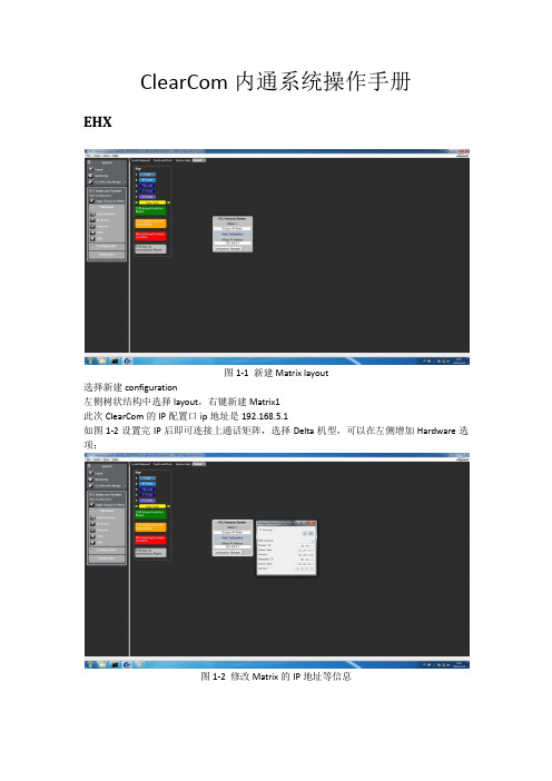
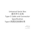
ClearCom内通系统操作手册EHX图1-1 新建Matrix layout选择新建configuration左侧树状结构中选择layout,右键新建Matrix1此次ClearCom的IP配置口ip地址是192.168.5.1如图1-2设置完IP后即可连接上通话矩阵,选择Delta机型,可以在左侧增加Hardware选项;图1-2 修改Matrix的IP地址等信息图1-3 右键选择Discovery Hardware如图1-3右键选择configuration -> create new configuration -> discovery hardware自动查找矩阵上的硬件;也可以指派Empty,进入Hardware的Cards and Panels手动添加对应槽位的硬件;图1-4 management可选择导入导出配置文件图1-4是configuration的保存和导入导出;还可以通过file -> user management 进行配置工程文件的导入导出,如图1-5所示;此处的Configuration是对应Project的矩阵设置数据表,每个通话矩阵可以有多个configuration,但是每次只能加载对应的一个configuration;图1-5 导入导出对应的配置文件和工程文件图1-6 查看card and panelsGo Online(No Merge)上线但不将当前配置设置到矩阵中;Go Online(EHX To System)合并当前EHX配置到矩阵;Go Online(System To EHX)将矩阵的配置下载到EHX;Go Online(Virual Merge)虚拟合并配置,并在有冲突时给予配置的优先级;此次我们一共配置了三块板卡,分别为MVX-A16、E-QUE FSⅡ和IVC-32Card slot第一块卡选择MVX-A16,这块模拟端口卡用于控制连接在卡上的面板和接口,通过5类网线发送平衡音频和422信号;我们在这块卡上设置了摄像机通话混音器MDIF1001、主持人返听UHF IFB TRANSmitter和演播室的PGM信号;在第三卡槽设置了E-Que FSⅡ用于FreeSpeak无线腰包供现场导演使用,具体配置如下所示在第四卡槽位置设置了IVC-32板卡,用于通过网络连接的各个导控和总控使用的通话面板,具体配置名称如图1-9,由于是网络接口,需要配置网络IP通讯口192.168.5.3,子网掩码255.255.255.0,默认网关192.168.5.254图1-7 E-Que FS Ⅱ板卡图1-8 设置天线的长度补偿如图1-8所示,右侧的页签Cable length Compensation根据天线与通话矩阵的位置设置对应的距离,系统可以提高对应端口的增益弥补信号的衰减;图1-9 设置IVC-32板卡的IP地址图1-10 设置板卡对应的User ID上图中User ID设置为bc1,Network设置LAN,Audio Codec设置G722;如遇面板坏了,可以直接通过设置IP地址(面板上不要插网线进行设置IP等参数,包括User ID等),设置完成后插上网线等待重启连接通话矩阵;图1-11 完成配置全部设置完成后,需要将配置写进通话矩阵内,点击Apply Change to Matrix跳出如图1-11的对话框,点击OK,等待矩阵完成配置;如何设置腰包图2-1 打开腰包的注册通道一个新的无线腰包该如何设置呢?1)首先给无线腰包装好电池2)安装好演播室用FS天线,在有效范围内使腰包可以通过天线接收到信号3)打开软件点击打开Enable Registration Mode,然后打开腰包电源选择对应系统PIN码,选择configuration内通名字如OCJ INTERCOM Configuration后,腰包就可以进入内通系统;4)点击软件上的Fetch Registed Beltpacks From Matrix添加系统认到的腰包ID等信息图2-2 设置腰包的通道和通话模式设置无线腰包的快捷标签,左侧页签选择Panels,上方的下拉页签选择到FD-A1 FreeSpeak 无线腰包,下方是矩阵Panels、Interfaces、Fixed Groups等音频源;将需要与无线腰包联系的TD、PD、VE、FD-A2拖拽上腰包的空档处,右键设置为Talk and Listen如何设置无线腰包角色图3-1 设置无线腰包的角色信息此次内通系统规划了ABCD四个演播室区域和总控系统工程师共5个无线腰包的角色;但由于需要考虑主备腰包同时使用等功能,因此设置了FD-A1/FD-A2、FD-B1/FD-B2、FD-C1/FD-C2、FD-D1/FD-D2、sys1/sys2共5个组;该页签下的右侧,可以设置无线腰包的输入输出增益、耳麦的侧音电平、电量报警、报警方式等设置(所有设置可以在腰包上长按manu进入菜单设置);图3-2 设置无线腰包的模式为No Default如图3-2所示,请选择No Default,其作用是每次打开腰包时能够选择想要的Beltpacks Roles,这样每个腰包之间都是可以互为备份的,而一旦一个腰包选择了一个角色后,其他腰包就无法再选择该角色,这就是角色唯一性;图3-3 Fixed Groups如图3-3所示,在左侧页签内选择Fixed Groups,添加对应的5组,每组添加2个无线腰包,分别设置了Talk and Listen,且组内的两个腰包也都设置了相互的标签可以直接通话,方便使用;通话面板的设置图4-1 选择对应的演播室面板一台新的通话面板如何接入系统中呢?1)通话面板接上电源,并插上网线;2)面板上manu进入菜单,再按面板右侧info,选择net config,设置对应的IP地址、子网掩码和默认网关;3)设置面板上的User ID和password;(需要选择已经在软件中设置的user id,且唯一);4)重启面板后就可以读取User ID对应的面板配置和PAGE信息;图4-2 选择对应的Panels、Interface、Fixed Groups等信号源图4-3 设置个性化的Page如图4-2所示,选择对应的面板类型信息,再选择对应的PAGE页数,即可设置对应的页面格局,其中面板上绿色的框是听,红色的框是说;在Panels页面上可以对面板的格局等信息配置进行保存和导入导出,还可以设置Audio Mixer 定义每块面板对矩阵输出进行配置输出节点,Identify panel可以点亮目标面板;如何设置无线腰包天线图5-1 pin码将无线腰包天线的通讯线接在E-Que FS板卡的后背板上,然后按照图5-1上的设置PIN码为0000,这样可以在无线腰包里输入PIN码,进入选择系统界面,可以将无线腰包加入到内通系统;图5-2 查看天线的状态灯图5-2上我们需要关注的是一个绿灯一个黄灯,绿灯代表电源,黄灯代表信号传输。
USB Type-C 规范1.2(中文版)
知识产权声明
THIS SPECIFICATION IS PROVIDED TO YOU “AS IS” WITH NO WARRANTIES WHATSOEVER, INCLUDING ANY WARRANTY OF MERCHANTABILITY, NON-INFRINGEMENT, OR FITNESS FOR ANY PARTICULAR PURPOSE. THE AUTHORS OF THIS SPECIFICATION DISCLAIM ALL LIABILITY, INCLUDING LIABILITY FOR INFRINGEMENT OF ANY PROPRIETARY RIGHTS, RELATING TO USE OR IMPLEMENTATION OF INFORMATION IN THIS SPECIFICATION. THE PROVISION OF THIS SPECIFICATION TO YOU DOES NOT PROVIDE YOU WITH ANY LICENSE, EXPRESS OR IMPLIED, BY ESTOPPEL OR OTHERWISE, TO ANY INTELLECTUAL PROPERTY RIGHTS.
预发行行业审查公司提供反馈
Revision History.......................................................................................................................14
LIMITED COPYRIGHT LICENSE: The USB 3.0 Promoters grant a conditional copyright license under the copyrights embodied in the USB Type-C Cable and Connector Specification to use and reproduce the Specification for the sole purpose of, and solely to the extent necessary for, evaluating whether to implement the Specification in products that would comply with the specification.
IMC02货币伪币检测器用户手册说明书

User ManualDocument Name:IMC02 User Manual-1.02.docxName Signature Date Prepared by: Byron ZhongReviewed by:Approved by:Version HistoryDate By Changes Version 2020-12-05 Byron Zhong ∙Initial Version 1.00 2021-1-16 Byron Zhong ∙Add the EUR/GBP Currency Detecting Section 1.01 2021-6-01 James Hu ∙Add the Maintenance 1.02∙∙ContentsVersion History (2)1.0.Overview (4)1.1.Preface (4)1.2.Abbreviation (4)2.0.Packing Open and Installation (5)2.1.Packing List (5)2.2.Power Supply (5)3.0.Operating Instructions (6)3.1.Display Appearance (6)3.2.Turn On/Off the Machine (6)3.3.Button Functions (6)3.3.1.CUR/DIR (6)3.3.2.REP/CLR (7)3.4.Inserting the Banknote Correctly (7)3.5.EUR/GBP Currency Detecting (7)4.0.Maintenance (9)4.1.Error Code (9)4.2.Inaccurate Detection of Currency Detector (9)5.0.Technical Parameters (10)1.0.Overview1.1.PrefaceThank you for purchasing our products. The IMC02 is the best solution for the banknote counterfeit detection. This user manual describes the operation steps and precautions for this product. In order to improve the use and working efficiency of the product, please read this manual carefully before using, so as to operate the product accurately. Please contact us if you encounter any problem.We reserve the right to change the contents of this user manual at any time without notice.Figure 1-1 IMC02 Counterfeit Detector1.2.AbbreviationTable 1-1 AbbreviationsAbbreviation DefinitionUSD United States DollarEUR EuroGBP Great Britain PoundLBP Lebanese PoundAED United Arab Emirates dirhamCFD Counterfeit DetectionIR InfraredMG MagneticUV Ultraviolet2.0.Packing Open and Installation2.1.Packing ListWhen you receive the package, open and check the packing list in the package.Table 2-1 Packing ListItem Name Picture Quantity (pcs) DescriptionCounterfeit Detector 1 Bill Counterfeit DetectorBattery 1 11.1V 500mAh rechargeable batteryPower Adapter 1 Power AdaptorUser Manual 12.2.Power SupplyDC Power: Connect the power adapter to a 110V or 220V outlet, then connect the terminal to the machine’s DC12V input socket.Lithium Battery (optional): When the battery was fully charged, the machine can work without power adapter.3.0. Operating Instructions3.1. Display AppearanceFigure 3-1 IMC02 Display Appearance3.2. Turn On/Off the MachineFigure 3-2 IMC02 Power InterfaceT u rn on the IMC02 by switch the power switch button to on, the screen will light up and the machine will start self-testing. If the self-test is successful, the number of banknote and the denomination will show as ‘0’. Turn off the IMC02 by switch the power switch to off. When the screen lights off, it means the machine has been turned off successfully.3.3. Button Functions3.3.1. CUR/DIRThe CUR/DIR button is used to choose the currency or the banknote exit direction.3.3.1.1. Choosing the CurrencyIn the detec tion mode, the IMC02 will recognize the currency type automatically, so pressing “CUR/DIR” button cannot choose the currencies manually.In the report mode, press the button to choose the currencies to check the report detail.Currency TypeBanknote ExitDirectionCUR/DIR ButtonNumber of BanknotesDenominationREP/CLR ButtonPower switch button3.3.1.2. Choosing the DirectionKeep pressing the button about 2 seconds until you hear the “di” sound, then release the button. The direction indicator will be changed.The denotation of direction will be shown on the top part of the display. Up means the genuine banknote will go out from exit and down means the genuine banknote will retreat from the feeding hopper.3.3.2. REP/CLRPress the button to check the pieces of each denomination, keep pressing the button for about 2 seconds to clear the records.After finish detecting banknotes, press “REP/CLR” to enter report mode. Display will show the currency type, pieces of each denomination and total value. You can switch to another currency by pressing “CUR/DIR”. While checking the record, if you feed banknote, the detector will automatically exit the report mode.3.4. Inserting the Banknote CorrectlyAs shown in the following pictures, please insert the banknotes in the left side. If a banknote was incorrectly inserted, the IMC02 may refuse it and alert.Figure 3-3 Banknote Insertion3.5. EUR/GBP Currency DetectingAs shown in the following figures, please remove the banknote feeding limit block to adjust the banknote with bigger size.Figure 3-4 Banknote InsertionRightWrongWrongThe banknote feeding limit blockFigure 3-5 EUR Banknote Detecting4.0. Maintenance4.1. Error CodeTable 1 Error codesCode Error Message Handing Method (recommendation)E01Length exceedsPlease check whether the banknote is in good condition and place the banknote to the left again.If the alarm continues, length calibration is required. E02 Length alarm E03 Half a banknote Please check if the banknote is complete. E06 Double banknote Please put in only one banknote. E07 Tilted banknote Please put the banknotes to the left.E10 Failed to refund Please check if your banknotes are too old or too soft. E11Basic image errorThis may be a counterfeit currency.Please check whether the banknotes are damaged, severely wrinkled, or dirty.E40UVPlease turn on the machine and clean the inside of the machine before checking banknotes.If the error continues, it means that the UV module has been damaged.E41 UV image error This may be a counterfeit currency. Please check whether the banknotes are damaged, severely wrinkled, or dirty.E60 Non-magnetic Please clean the inside of the machine.Please check whether there is magnetic interference around themachine.If the error continues, it means that the magnetic module is damaged.E61 Magnetic pulse 1 alarmE62 Magnetic pulse 2 alarm E63 Magnetic pulse 3 alarmE64 Too much magnetism E65 Magnetic prefixE66 Image magnetism error Please check if your banknotes are counterfeit.4.2. Inaccurate Detection of Currency DetectorThere are several conditions to affect the accuracy of the currency detector.1) The bill size is out of the range according to IMC02 specification.2) The banknote is damaged with different ways such as lack of corner, tape, hole, tear and folded. As shownin Figure 4-1, it is not recommended to count this kind of bills.Figure 4-1 Bill Damaged Ways3)Other abnormal operation or there is unknown thing inside the IMC02.If something inside the IMC02, youneed to open the front cover to check, and clean the internal sensors.4.3.‘ADD’ function settingsUse the following steps to turn on/off the Add function.1)Press ‘CUR/DIP’ and ‘REP/CLR’ at the same time for 5 seconds to enter the selection interface.2)Press and hold the ‘CUR/DIP’ and ‘REP/CLR’ buttons simultaneously on the d_1 interface for 2 seconds toenter the function selection interface.3)Press the ‘CUR/DIP’ button 3 times to switch the mode to P22, and finally press and hold the ‘REP/CLR’to switch the value of P22 to 0 to turn on the Add function, and switch the value of P22 to 1 to turn off the Add function.Demo video: https:///IMC02ADDPage11of125.0. Technical ParametersTable 2 Technical Parameters Counterfeit DetectionMG (Magnetic), IR (Infrared), UV (Ultraviolet) Error DetectionImage, paper quality, size, thickness detection Available currenciesUSD, EUR, GBP, LBP, AED, MXN DisplayLED display ButtonCUR/DIR, REP/CLR InterfaceUSB, software upgrade interface Detecting Speed<0.5 seconds/piece Power Consumption<10W Power SupplyBatteryAC 100V-240V 50-60Hz or DC 12V/1.0A Rechargeable lithium battery 11.1V / 500 mAh CertificationsCE, FCC, ROHS Operating Temperature0°C - 40°C Storage Temperature-20°C - 65°C Counterfeit DetectionMG (Magnetic), IR (Infrared), UV (Ultraviolet) Error DetectionImage, paper quality, size, thickness detection Available currenciesUSD, EUR, GBP, LBP, AED, MXNScan the QR code for Facebook online chatContact usOUTLOOK: ******************Whatsapp: +86-178********If you meet any problem during using the IMC01, please contact us.。
HP Color LaserJet Enterprise MFP M776用户指南说明书
Legal informationCopyright and License© Copyright 2019 HP Development Company, L.P.Reproduction, adaptation, or translation without prior written permission is prohibited, except as allowedunder the copyright laws.The information contained herein is subject to change without notice.The only warranties for HP products and services are set forth in the express warranty statementsaccompanying such products and services. Nothing herein should be construed as constituting anadditional warranty. HP shall not be liable for technical or editorial errors or omissions contained herein.Edition 1, 10/2019Trademark CreditsAdobe®, Adobe Photoshop®, Acrobat®, and PostScript® are trademarks of Adobe Systems Incorporated.Apple and the Apple logo are trademarks of Apple Inc., registered in the U.S. and other countries.macOS is a trademark of Apple Inc., registered in the U.S. and other countries.AirPrint is a trademark of Apple Inc., registered in the U.S. and other countries.Google™ is a trademark of Google Inc.Microsoft®, Windows®, Windows® XP, and Windows Vista® are U.S. registered trademarks of MicrosoftCorporation.UNIX® is a registered trademark of The Open Group.iiiT able of contents1 Printer overview (1)Warning icons (1)Potential shock hazard (2)Printer views (2)Printer front view (2)Printer back view (4)Interface ports (4)Control-panel view (5)How to use the touchscreen control panel (7)Printer specifications (8)T echnical specifications (8)Supported operating systems (11)Mobile printing solutions (12)Printer dimensions (13)Power consumption, electrical specifications, and acoustic emissions (15)Operating-environment range (15)Printer hardware setup and software installation (16)2 Paper trays (17)Introduction (17)Load paper to Tray 1 (multipurpose tray) (17)Load Tray 1 (multipurpose tray) (18)Tray 1 paper orientation (19)Use alternative letterhead mode (24)Enable Alternative Letterhead Mode by using the printer control-panel menus (24)Load paper to Tray 2 (24)Load Tray 2 (24)Tray 2 paper orientation (26)Use alternative letterhead mode (29)Enable Alternative Letterhead Mode by using the printer control-panel menus (29)Load paper to the 550-sheet paper tray (30)Load paper to the 550-sheet paper tray (30)550-sheet paper tray paper orientation (32)Use alternative letterhead mode (35)Enable Alternative Letterhead Mode by using the printer control-panel menus (35)ivLoad paper to the 2 x 550-sheet paper trays (36)Load paper to the 2 x 550-sheet paper trays (36)2 x 550-sheet paper tray paper orientation (38)Use alternative letterhead mode (41)Enable Alternative Letterhead Mode by using the printer control-panel menus (41)Load paper to the 2,700-sheet high-capacity input paper trays (41)Load paper to the 2,700-sheet high-capacity input paper trays (41)2,700-sheet HCI paper tray paper orientation (43)Use alternative letterhead mode (45)Enable Alternative Letterhead Mode by using the printer control-panel menus (45)Load and print envelopes (46)Print envelopes (46)Envelope orientation (46)Load and print labels (47)Manually feed labels (47)Label orientation (48)3 Supplies, accessories, and parts (49)Order supplies, accessories, and parts (49)Ordering (49)Supplies and accessories (50)Maintenance/long-life consumables (51)Customer self-repair parts (51)Dynamic security (52)Configure the HP toner-cartridge-protection supply settings (53)Introduction (53)Enable or disable the Cartridge Policy feature (53)Use the printer control panel to enable the Cartridge Policy feature (54)Use the printer control panel to disable the Cartridge Policy feature (54)Use the HP Embedded Web Server (EWS) to enable the Cartridge Policy feature (54)Use the HP Embedded Web Server (EWS) to disable the Cartridge Policy feature (55)Troubleshoot Cartridge Policy control panel error messages (55)Enable or disable the Cartridge Protection feature (55)Use the printer control panel to enable the Cartridge Protection feature (56)Use the printer control panel to disable the Cartridge Protection feature (56)Use the HP Embedded Web Server (EWS) to enable the Cartridge Protection feature (56)Use the HP Embedded Web Server (EWS) to disable the Cartridge Protection feature (57)Troubleshoot Cartridge Protection control panel error messages (57)Replace the toner cartridges (58)T oner-cartridge information (58)Remove and replace the cartridges (59)Replace the imaging drums (62)Imaging drum information (62)Remove and replace the imaging drums (63)Replace the toner-collection unit (66)T oner-collection unit information (66)vRemove and replace the toner-collection unit (67)Replace the staple cartridge (M776zs model only) (70)Staple cartridge information (70)Remove and replace the staple cartridge (71)4 Print (73)Print tasks (Windows) (73)How to print (Windows) (73)Automatically print on both sides (Windows) (74)Manually print on both sides (Windows) (74)Print multiple pages per sheet (Windows) (75)Select the paper type (Windows) (75)Additional print tasks (76)Print tasks (macOS) (77)How to print (macOS) (77)Automatically print on both sides (macOS) (77)Manually print on both sides (macOS) (77)Print multiple pages per sheet (macOS) (78)Select the paper type (macOS) (78)Additional print tasks (79)Store print jobs on the printer to print later or print privately (79)Introduction (79)Create a stored job (Windows) (79)Create a stored job (macOS) (80)Print a stored job (81)Delete a stored job (81)Delete a job that is stored on the printer (81)Change the job storage limit (82)Information sent to printer for Job Accounting purposes (82)Mobile printing (82)Introduction (82)Wi-Fi, Wi-Fi Direct Print, NFC, and BLE printing (82)Enable wireless printing (83)Change the Wi-Fi Direct name (83)HP ePrint via email (83)AirPrint (84)Android embedded printing (85)Print from a USB flash drive (85)Enable the USB port for printing (85)Method one: Enable the USB port from the printer control panel (85)Method two: Enable the USB port from the HP Embedded Web Server (network-connectedprinters only) (85)Print USB documents (86)Print using high-speed USB 2.0 port (wired) (86)Method one: Enable the high-speed USB 2.0 port from the printer control panel menus (86)Method two: Enable the high-speed USB 2.0 port from the HP Embedded Web Server (network-connected printers only) (87)vi5 Copy (88)Make a copy (88)Copy on both sides (duplex) (90)Additional copy tasks (92)6 Scan (93)Set up Scan to Email (93)Introduction (93)Before you begin (93)Step one: Access the HP Embedded Web Server (EWS) (94)Step two: Configure the Network Identification settings (95)Step three: Configure the Send to Email feature (96)Method one: Basic configuration using the Email Setup Wizard (96)Method two: Advanced configuration using the Email Setup (100)Step four: Configure the Quick Sets (optional) (104)Step five: Set up Send to Email to use Office 365 Outlook (optional) (105)Introduction (105)Configure the outgoing email server (SMTP) to send an email from an Office 365 Outlookaccount (105)Set up Scan to Network Folder (108)Introduction (108)Before you begin (108)Step one: Access the HP Embedded Web Server (EWS) (108)Step two: Set up Scan to Network Folder (109)Method one: Use the Scan to Network Folder Wizard (109)Method two: Use Scan to Network Folder Setup (110)Step one: Begin the configuration (110)Step two: Configure the Scan to Network Folder settings (111)Step three: Complete the configuration (118)Set up Scan to SharePoint (118)Introduction (118)Before you begin (118)Step one: Access the HP Embedded Web Server (EWS) (118)Step two: Enable Scan to SharePoint and create a Scan to SharePoint Quick Set (119)Scan a file directly to a SharePoint site (121)Quick Set scan settings and options for Scan to SharePoint (122)Set up Scan to USB Drive (123)Introduction (124)Step one: Access the HP Embedded Web Server (EWS) (124)Step two: Enable Scan to USB Drive (124)Step three: Configure the Quick Sets (optional) (125)Default scan settings for Scan to USB Drive setup (126)Default file settings for Save to USB setup (126)Scan to email (127)Introduction (127)Scan to email (127)Scan to job storage (129)viiIntroduction (129)Scan to job storage on the printer (130)Print from job storage on the printer (132)Scan to network folder (132)Introduction (132)Scan to network folder (132)Scan to SharePoint (134)Introduction (134)Scan to SharePoint (134)Scan to USB drive (136)Introduction (136)Scan to USB drive (136)Use HP JetAdvantage business solutions (138)Additional scan tasks (138)7 Fax (140)Set up fax (140)Introduction (140)Set up fax by using the printer control panel (140)Change fax configurations (141)Fax dialing settings (141)General fax send settings (142)Fax receive settings (143)Send a fax (144)Additional fax tasks (146)8 Manage the printer (147)Advanced configuration with the HP Embedded Web Server (EWS) (147)Introduction (147)How to access the HP Embedded Web Server (EWS) (148)HP Embedded Web Server features (149)Information tab (149)General tab (149)Copy/Print tab (150)Scan/Digital Send tab (151)Fax tab (152)Supplies tab (153)Troubleshooting tab (153)Security tab (153)HP Web Services tab (154)Networking tab (154)Other Links list (156)Configure IP network settings (157)Printer sharing disclaimer (157)View or change network settings (157)Rename the printer on a network (157)viiiManually configure IPv4 TCP/IP parameters from the control panel (158)Manually configure IPv6 TCP/IP parameters from the control panel (158)Link speed and duplex settings (159)Printer security features (160)Introduction (160)Security statements (160)Assign an administrator password (160)Use the HP Embedded Web Server (EWS) to set the password (160)Provide user access credentials at the printer control panel (161)IP Security (161)Encryption support: HP High Performance Secure Hard Disks (161)Lock the formatter (161)Energy-conservation settings (161)Set the sleep timer and configure the printer to use 1 watt or less of power (161)Set the sleep schedule (162)Set the idle settings (162)HP Web Jetadmin (163)Software and firmware updates (163)9 Solve problems (164)Customer support (164)Control panel help system (165)Reset factory settings (165)Introduction (165)Method one: Reset factory settings from the printer control panel (165)Method two: Reset factory settings from the HP Embedded Web Server (network-connectedprinters only) (166)A “Cartridge is low” or “Cartridge is very low” message displays on the printer control panel (166)Change the “Very Low” settings (166)Change the “Very Low” settings at the control panel (166)For printers with fax capability (167)Order supplies (167)Printer does not pick up paper or misfeeds (167)Introduction (167)The printer does not pick up paper (167)The printer picks up multiple sheets of paper (171)The document feeder jams, skews, or picks up multiple sheets of paper (174)Clear paper jams (174)Introduction (174)Paper jam locations (174)Auto-navigation for clearing paper jams (175)Experiencing frequent or recurring paper jams? (175)Clear paper jams in the document feeder - 31.13.yz (176)Clear paper jams in Tray 1 (13.A1) (177)Clear paper jams in Tray 2 (13.A2) (182)Clear paper jams in the fuser (13.B9, 13.B2, 13.FF) (188)ixClear paper jams in the duplex area (13.D3) (194)Clear paper jams in the 550-sheet trays (13.A3, 13.A4) (199)Clear paper jams in the 2 x 550 paper trays (13.A4, 13.A5) (206)Clear paper jams in the 2,700-sheet high-capacity input paper trays (13.A3, 13.A4, 13.A5, 13.A7) (213)Resolving color print quality problems (220)Introduction (220)Troubleshoot print quality (221)Update the printer firmware (221)Print from a different software program (221)Check the paper-type setting for the print job (221)Check the paper type setting on the printer (221)Check the paper type setting (Windows) (221)Check the paper type setting (macOS) (222)Check toner-cartridge status (222)Step one: Print the Supplies Status Page (222)Step two: Check supplies status (222)Print a cleaning page (222)Visually inspect the toner cartridge or cartridges (223)Check paper and the printing environment (223)Step one: Use paper that meets HP specifications (223)Step two: Check the environment (223)Step three: Set the individual tray alignment (224)Try a different print driver (224)Troubleshoot color quality (225)Calibrate the printer to align the colors (225)Troubleshoot image defects (225)Improve copy image quality (233)Check the scanner glass for dirt and smudges (233)Calibrate the scanner (234)Check the paper settings (235)Check the paper selection options (235)Check the image-adjustment settings (235)Optimize copy quality for text or pictures (236)Edge-to-edge copying (236)Improve scan image quality (236)Check the scanner glass for dirt and smudges (237)Check the resolution settings (238)Check the color settings (238)Check the image-adjustment settings (239)Optimize scan quality for text or pictures (239)Check the output-quality settings (240)Improve fax image quality (240)Check the scanner glass for dirt and smudges (240)Check the send-fax resolution settings (242)Check the image-adjustment settings (242)Optimize fax quality for text or pictures (242)Check the error-correction setting (243)xSend to a different fax machine (243)Check the sender's fax machine (243)Solve wired network problems (244)Introduction (244)Poor physical connection (244)The computer is unable to communicate with the printer (244)The printer is using incorrect link and duplex settings for the network (245)New software programs might be causing compatibility problems (245)The computer or workstation might be set up incorrectly (245)The printer is disabled, or other network settings are incorrect (245)Solve wireless network problems (245)Introduction (245)Wireless connectivity checklist (245)The printer does not print after the wireless configuration completes (246)The printer does not print, and the computer has a third-party firewall installed (246)The wireless connection does not work after moving the wireless router or printer (247)Cannot connect more computers to the wireless printer (247)The wireless printer loses communication when connected to a VPN (247)The network does not appear in the wireless networks list (247)The wireless network is not functioning (247)Reduce interference on a wireless network (248)Solve fax problems (248)Checklist for solving fax problems (248)What type of phone line are you using? (249)Are you using a surge-protection device? (249)Are you using a phone company voice-messaging service or an answering machine? (249)Does your phone line have a call-waiting feature? (249)Check fax accessory status (249)General fax problems (250)The fax failed to send (250)No fax address book button displays (250)Not able to locate the Fax settings in HP Web Jetadmin (250)The header is appended to the top of the page when the overlay option is enabled (251)A mix of names and numbers is in the recipients box (251)A one-page fax prints as two pages (251)A document stops in the document feeder in the middle of faxing (251)The volume for sounds coming from the fax accessory is too high or too low (251)Index (252)xiPrinter overview1Review the location of features on the printer, the physical and technical specifications of the printer,and where to locate setup information.For video assistance, see /videos/LaserJet.The following information is correct at the time of publication. For current information, see /support/colorljM776MFP.For more information:HP's all-inclusive help for the printer includes the following information:●Install and configure●Learn and use●Solve problems●Download software and firmware updates●Join support forums●Find warranty and regulatory informationWarning iconsUse caution if you see a warning icon on your HP printer, as indicated in the icon definitions.●Caution: Electric shock●Caution: Hot surface●Caution: Keep body parts away from moving partsPrinter overview1●Caution: Sharp edge in close proximity●WarningPotential shock hazardReview this important safety information.●Read and understand these safety statements to avoid an electrical shock hazard.●Always follow basic safety precautions when using this product to reduce risk of injury from fire orelectric shock.●Read and understand all instructions in the user guide.●Observe all warnings and instructions marked on the product.●Use only a grounded electrical outlet when connecting the product to a power source. If you do notknow whether the outlet is grounded, check with a qualified electrician.●Do not touch the contacts on any of the sockets on the product. Replace damaged cordsimmediately.●Unplug this product from wall outlets before cleaning.●Do not install or use this product near water or when you are wet.●Install the product securely on a stable surface.●Install the product in a protected location where no one can step on or trip over the power cord.Printer viewsIdentify certain parts of the printer and the control panel.Printer front viewLocate features on the front of the printer.2Chapter 1 Printer overviewPrinter front view3Printer back viewLocate features on the back of the printer.Interface portsLocate the interface ports on the printer formatter. 4Chapter 1 Printer overviewControl-panel viewThe control panel provides access to the printer features and indicates the current status of the printer.NOTE:Tilt the control panel for easier viewing.The Home screen provides access to the printer features and indicates the current status of the printer.screens.NOTE:The features that appear on the Home screen can vary, depending on the printerconfiguration.Control-panel view5Figure 1-1Control-panel view?i 12:42 PM6Chapter 1 Printer overviewHow to use the touchscreen control panelPerform the following actions to use the printer touchscreen control panel.T ouchT ouch an item on the screen to select that item or open that menu. Also, when scrolling T ouch the Settings icon to open the Settings app.How to use the touchscreen control panel 7SwipeT ouch the screen and then move your finger horizontally to scroll the screen sideways.Swipe until the Settings app displays.Printer specificationsDetermine the specifications for your printer model.IMPORTANT:The following specifications are correct at the time of publication, but they are subject to change. For current information, see /support/colorljM776MFP .T echnical specificationsReview the printer technical specifications.Product numbers for each model ●M776dn - #T3U55A ●Flow M776z - #3WT91A ●Flow M776zs - #T3U56APaper handling specificationsPaper handling features Tray 1 (100-sheet capacity)Included Included Included Tray 2 (550-sheet capacity)IncludedIncludedIncluded8Chapter 1 Printer overview550-sheet paper trayOptional Included Not included NOTE:The M776dn models accept one optional550-sheet tray.Optional Included Included2 x 550-sheet paper tray and standNOTE:The M776dn models accept one optional550-sheet tray that may be installed on top of thestand.Optional Not included Not included2,700-sheet high-capacity input (HCI) paper trayand standNOTE:The M776dn models accept one optional550-sheet tray that may be installed on top of theoptional printer stand.Printer standOptional Not included Not included NOTE:The M776dn models accept one optional550-sheet tray that may be installed on top of theoptional printer stand.Inner finisher accessory Not included Not included Included Automatic duplex printing Included IncludedIncludedIncluded Included Included10/100/1000 Ethernet LAN connection with IPv4and IPv6Hi-Speed USB 2.0Included Included IncludedIncluded Included IncludedEasy-access USB port for printing from a USBflash drive or upgrading the firmwareIncluded Included Included Hardware Integration Pocket for connectingaccessory and third-party devicesHP Internal USB Ports Optional Optional OptionalOptional Optional OptionalHP Jetdirect 2900nw Print Server accessory forWi-Fi connectivity and an additional Ethernet portOptional IncludedIncludedHP Jetdirect 3100w accessory for Wi-Fi, BLE, NFC,and proximity badge readingPrints 45 pages per minute (ppm) on Letter-sizepaper and 46 ppm on A4-size paperEasy-access USB printing for printing from a USBIncluded Included Includedflash driveT echnical specifications9Included Included Included Store jobs in the printer memory to print later orprint privatelyScans 100 pages per minute (ppm) on A4 andIncluded Included Included letter-size paper one-sidedIncluded Included Included 200-page document feeder with dual-headscanning for single-pass duplex copying andscanningNot included Included Included HP EveryPage T echnologies including ultrasonicmulti-feed detectionNot included Included Included Embedded optical character recognition (OCR)provides the ability to convert printed pages intotext that can be edited or searched using acomputerIncluded Included Included SMART Label feature provides paper-edgedetection for automatic page croppingIncluded Included Included Automatic page orientation for pages that haveat least 100 characters of textIncluded Automatic tone adjustment sets contrast,Included Includedbrightness, and background removal for eachpageIncluded Included Includedfolders on a networkIncludedSend documents to SharePoint®Included IncludedIncluded Included Included NOTE:Memory reported on the configurationpage will change from 2.5 GB to 3 GB with theoptional 1 GB SODIMM installed.Mass storage: 500 GB hard disk drive Included Included IncludedSecurity: HP Trusted Platform Module (TPM)Included Included IncludedT ouchscreen control panel Included Included IncludedRetractable keyboard Not included Included Included 10Chapter 1 Printer overviewFax Optional Included IncludedSupported operating systemsUse the following information to ensure printer compatibility with your computer operating system.Linux: For information and print drivers for Linux, go to /go/linuxprinting.UNIX: For information and print drivers for UNIX®, go to /go/unixmodelscripts.The following information applies to the printer-specific Windows HP PCL 6 print drivers, HP print driversfor macOS, and to the software installer.Windows: Download HP Easy Start from /LaserJet to install the HP print driver. Or, go tothe printer-support website for this printer: /support/colorljM776MFP to download the printdriver or the software installer to install the HP print driver.macOS: Mac computers are supported with this printer. Download HP Easy Start either from /LaserJet or from the Printer Support page, and then use HP Easy Start to install the HP print driver.1.Go to /LaserJet.2.Follow the steps provided to download the printer software.Windows 7, 32-bit and 64-bit The “HP PCL 6” printer-specific print driver is installed for this operating system aspart of the software installation.Windows 8.1, 32-bit and 64-bit The “HP PCL-6” V4 printer-specific print driver is installed for this operating systemas part of the software installation.Windows 10, 32-bit and 64-bit The “HP PCL-6” V4 printer-specific print driver is installed for this operating systemas part of the software installation.Windows Server 2008 R2, SP 1, 64-bit The PCL 6 printer-specific print driver is available for download from the printer-support website. Download the driver, and then use the Microsoft Add Printer tool toinstall it.Windows Server 2012, 64-bit The PCL 6 printer-specific print driver is available for download from the printer-support website. Download the driver, and then use the Microsoft Add Printer tool toinstall it.Windows Server 2012 R2, 64-bit The PCL 6 printer-specific print driver is available for download from the printer-support website. Download the driver, and then use the Microsoft Add Printer tool toinstall it.Windows Server 2016, 64-bit The PCL 6 printer-specific print driver is available for download from the printer-support website. Download the driver, and then use the Microsoft Add Printer tool toinstall it.Windows Server 2019, 64-bit The PCL 6 printer-specific print driver is available for download from the printer-support website. Download the driver, and then use the Microsoft Add Printer tool toinstall it.Supported operating systems11macOS 10.13 High Sierra, macOS 10.14 MojaveDownload HP Easy Start from /LaserJet , and then use it to install the print driver.NOTE:Supported operating systems can change.NOTE:For a current list of supported operating systems and HP’s all-inclusive help for the printer, go to /support/colorljM776MFP .NOTE:For details on client and server operating systems and for HP UPD driver support for this printer, go to /go/upd . Under Additional information , click Specifications .●Internet connection●Dedicated USB 1.1 or 2.0 connection or a network connection● 2 GB of available hard-disk space ●1 GB RAM (32-bit) or2 GB RAM (64-bit)●Internet connection●Dedicated USB 1.1 or 2.0 connection or a network connection●1.5 GB of available hard-disk spaceNOTE:The Windows software installer installs the HP Smart Device Agent Base service. The file size is less than 100 kb. Its only function is to check for printers connected via USB hourly. No data is collected. If a USB printer is found, it then tries to locate a JetAdvantage Management Connector (JAMc) instance on the network. If a JAMc is found, the HP Smart Device Agent Base is securelyupgraded to a full Smart Device Agent from JAMc, which will then allow printed pages to be accounted for in a Managed Print Services (MPS) account. The driver-only web packs downloaded from for the printer and installed through the Add Printer wizard do not install this service.T o uninstall the service, open the Control Panel , select Programs or Programs and Features , and then select Add/Remove Programs or Uninstall a Programto remove the service. The file name isHPSmartDeviceAgentBase.Mobile printing solutionsHP offers multiple mobile printing solutions to enable easy printing to an HP printer from a laptop, tablet, smartphone, or other mobile device.T o see the full list and to determine the best choice, go to /go/MobilePrinting .NOTE:Update the printer firmware to ensure all mobile printing capabilities are supported.●Wi-Fi Direct (wireless models only, with HP Jetdirect 3100w BLE/NFC/Wireless accessory installed)●HP ePrint via email (Requires HP Web Services to be enabled and the printer to be registered with HP Connected)●HP Smart app ●Google Cloud Print12Chapter 1 Printer overview。
气泡混合轻质土使用规程
目次1总则 (3)2术语和符号 (4)2.1 术语 (4)2.2 符号 (5)3材料及性能 (6)3.1 原材料 (6)3.2 性能 (6)4设计 (8)4.1 一般规定 (8)4.2 性能设计 (8)4.3 结构设计 (9)4.4 附属工程设计 (10)4.5 设计计算 (10)5配合比 (13)5.1 一般规定 (13)5.2 配合比计算 (13)5.3 配合比试配 (14)5.4 配合比调整 (14)6工程施工 (15)6.1 浇筑准备 (15)6.2 浇筑 (15)6.3 附属工程施工 (15)6.4 养护 (16)7质量检验与验收 (17)7.1 一般规定 (17)7.2 质量检验 (17)7.3 质量验收 (18)附录A 发泡剂性能试验 (20)附录B 湿容重试验 (22)附录C 适应性试验 (22)附录D 流动度试验 (24)附录E 干容重、饱水容重试验 (25)附录F 抗压强度、饱水抗压强度试验 (27)附录G 工程质量检验验收用表 (28)本规程用词说明 (35)引用标准名录 (36)条文说明 (37)Contents1.General provisions (3)2.Terms and symbols (4)2.1 Terms (4)2.2 Symbols (5)3. Materials and properties (6)3.1 Materials (6)3.2 properties (6)4. Design (8)4.1 General provisions (8)4.2 Performance design (8)4.3 Structure design (9)4.4 Subsidiary engineering design (9)4.5 Design calculation (10)5. Mix proportion (13)5.1 General provisions (13)5.2 Mix proportion calculation (13)5.3 Mix proportion trial mix (14)5.4 Mix proportion adjustment (14)6. Engineering construction (15)6.1 Construction preparation (15)6.2 Pouring .............................................................. .. (15)6.3 Subsidiary engineering construction (16)6.4 Maintenance (17)7 Quality inspection and acceptance (18)7.1 General provisions (18)7.2 Quality evaluate (18)7.3 Quality acceptance (19)Appendix A Test of foaming agent performance (20)Appendix B Wet density test (22)Appendix C Adaptability test (23)Appendix D Flow value test.................................................................................. .. (24)Appendix E Air-dry density and saturated density test (25)Appendix F Compressive strength and saturated compressive strength test (27)Appendix G Table of evaluate and acceptance for quality (28)Explanation of Wording in this code (35)Normative standard (36)Descriptive provision (37)1总则1.0.1为规范气泡混合轻质土的设计、施工,统一质量检验标准,保证气泡混合轻质土填筑工程安全适用、技术先进、经济合理,制订本规程。
雷赛BASIC编程手册v2.1
3.2.7 STOP ...............................................................................................................18
3.2.8 AUTO..............................................................................................................18
3.3.1 运算符.............................................................................................................19
3.3.2 ABS.................................................................................................................22
3.2.3 SUB.................................................................................................................17
3.2.4 ON GOSUB ....................................................................................................18
雷赛运动控制器 BASIC 语言编程手册
Version 2.1
- 1、下载文档前请自行甄别文档内容的完整性,平台不提供额外的编辑、内容补充、找答案等附加服务。
- 2、"仅部分预览"的文档,不可在线预览部分如存在完整性等问题,可反馈申请退款(可完整预览的文档不适用该条件!)。
- 3、如文档侵犯您的权益,请联系客服反馈,我们会尽快为您处理(人工客服工作时间:9:00-18:30)。
CLEAR-COM WIRELESS IFBPRC-2UHF MULTI-FREQUENCY BELT-PACK IFBRECEIVERINSTRUCTION MANUALPRC-2 UHF Multi-Frequency Belt-Pack IFB Receiver Instruction Manual© 2008 Vitec Group Communications Ltd. All rights reserved.Part Number 810400Z Rev. 2Vitec Group Communications LLC850 Marina Village ParkwayAlameda, CA 94501U.S.AVitec Group Communications Ltd7400 Beach DriveIQ CambridgeCambridgeshireUnited KingdomCB25 9TPVitec Group CommunicationsRoom 1806, Hua Bin BuildingNo. 8 Yong An Dong LiJian Guo Men Wai AveChao Yang DistrictBeijing, P.R. China 100022® Clear-Com, CellCom/FreeSpeak and the Clear-Com Communication Systems logo are registered trademarks of The Vitec Group plc.CONTENTSINTRODUCTION. . . . . . . . . . . . . . . . . . . . . . . . . . . 1-1Introduction. . . . . . . . . . . . . . . . . . . . . . . . . . . . . . . . . . . . . . . . . . . .1-1General Technical Description . . . . . . . . . . . . . . . . . . . . . . . . . . . . .1-1General Features . . . . . . . . . . . . . . . . . . . . . . . . . . . . . . . . . . . . . . .1-2Control Knob. . . . . . . . . . . . . . . . . . . . . . . . . . . . . . . . . . . . . . . . .1-2LED Indicator . . . . . . . . . . . . . . . . . . . . . . . . . . . . . . . . . . . . . . . .1-3Headphone Jack. . . . . . . . . . . . . . . . . . . . . . . . . . . . . . . . . . . . . .1-3Mono Plug/Stereo Plug Usage . . . . . . . . . . . . . . . . . . . . . . . . . . .1-4Audio Level. . . . . . . . . . . . . . . . . . . . . . . . . . . . . . . . . . . . . . . . . .1-4Frequency Adjustment . . . . . . . . . . . . . . . . . . . . . . . . . . . . . . . . .1-4Receiver Operating Instructions. . . . . . . . . . . . . . . . . . . . . . . . . . . .1-6Receiver Normal Operation (already programmed) . . . . . . . . . . .1-6Programming- Add a New Frequency To the Next Open Channel1-6Erase All 5 Channel Memories . . . . . . . . . . . . . . . . . . . . . . . . . . .1-7Multiple Transmitter Setup . . . . . . . . . . . . . . . . . . . . . . . . . . . . . .1-7Battery Instructions. . . . . . . . . . . . . . . . . . . . . . . . . . . . . . . . . . . .1-8Troubleshooting . . . . . . . . . . . . . . . . . . . . . . . . . . . . . . . . . . . . . . .1-10SPECIFICATIONS. . . . . . . . . . . . . . . . . . . . . . . . . . 2-1LIMITED WARRANTY. . . . . . . . . . . . . . . . . . . . . . .W-IWarranty Period . . . . . . . . . . . . . . . . . . . . . . . . . . . . . . . . . . . . . . . .W-iTechnical Support. . . . . . . . . . . . . . . . . . . . . . . . . . . . . . . . . . . . . . .W-iWarranty Repairs and Returns. . . . . . . . . . . . . . . . . . . . . . . . . . . . W-iiNon-Warranty Repairs and Returns . . . . . . . . . . . . . . . . . . . . . . . . W-iiExtended Warranty. . . . . . . . . . . . . . . . . . . . . . . . . . . . . . . . . . . . . W-iiLiability . . . . . . . . . . . . . . . . . . . . . . . . . . . . . . . . . . . . . . . . . . . . . .W-iii Vitec Group Communicationsi PRC-2 UHF Multi-Frequency Belt-Pack IFB ReceiverVitec Group Communications iiPRC-2 UHF Multi-Frequency Belt-Pack IFB ReceiverVitec Group Communications PRC-2 UHF Multi-Frequency Belt-Pack IFB Receiver i i iIMPORTANT SAFETY INSTRUCTIONS1. Read these instructions.2. Keep these instructions.3. Heed all warnings.4. Follow all instructions.5. Do not use this apparatus near water.6. Clean only with dry cloth.7. Do not block any ventilation openings. Install in accordance with themanufacturer’s instructions.8. Do not install near any heat sources such as radiators, heatregisters, stoves, or other apparatus (including amplifiers) thatproduce heat.9. Only use attachments/accessories specified by the manufacturer.10. Use only with the cart, stand, tripod, bracket, or table specified bythe manufacturer, or sold with the apparatus. When a cart is used,use caution when moving the cart/apparatus combination to avoidinjury from tip-over.11. Unplug this apparatus during lightning storms or when unused forlong periods of time.12. Refer all servicing to qualified service personnel. Servicing isrequired when the apparatus has been damaged in any way, suchas power-supply cord or plug is damaged, liquid has been spilled orobjects have fallen into the apparatus, the apparatus has beenexposed to rain or moisture, does not operate normally, or has beendropped.13. WARNING: To reduce the risk of fire or electric shock, do notexpose this product to rain or moisture.SAFETY NOTESExcessive sound levels can cause permanent hearing damage.1. Always adjust the volume to the lowest level before listening tounknown transmissions.2. Use the lowest reasonable level consistent with hearing safety.3. Do not use high sound levels in the earphone to overcome highambient sound levels. That is absolutely foolish! Demand and usehigh isolation earphones.4. Do not expose your ears to sound levels that cause them to ring. Ifyour ears do ring after exposure, think of it as a warning bell tellingyou not to do that again.Please read and follow these instructions before operating this product.Vitec Group Communications PRC-2 UHF Multi-Frequency Belt-Pack IFB Receiveri v OSHA (Occupational Safety Health Administration) guidelines onthe maximum allowable time exposure to sound pressure levelsthat will cause hearing damage are as follows:Never expose your ears to 120dB SPL or higher/ Damage willoccur.Please familiarize yourself with the safety symbols in Figure 1.When you see these symbols on this product, they warn you ofthe potential danger of electric shock if the station is usedimproperly. They also refer you to important operating andmaintenance instructions in the manual.Figure 1: Safety Symbols 8 hoursat 90dB SPL 4 hoursat 95dB SPL 2 hoursat 100dB SPL 1 hourat 105dB SPL 30 minsat 110dB SPL 15 min at 115dB SPLVitec Group CommunicationsPRC-2 UHF Multi-Frequency Belt-Pack IFB Receiver 1-1INTRODUCTIONINTRODUCTIONThank you for selecting the ClearCom frequency agile, PRC-2 IFBReceiver. The PRC-2 is the result of extensive engineering experiencewith the very latest components. The design addresses the mostdemanding professional applications.Figure 1-1: PRC-2 IFB ReceiverThe ClearCom PRC-2 Receiver along with the companion PTX-3transmitter allow on-air talent to monitor program audio, and to receivecues from directors and other production personnel.The PRC-2 Receiver is housed in a rugged, machined aluminumpackage for lasting performance in abusive environmentsOnly the PRC-2 IFB Receiver is covered in this manual. Thecompanion PTX-3 transmitter is covered in a separate manual. ThePRC-2 IFB Receive will operate with any ClearCom PTX-3 IFBTransmitter in the same frequency block.GENERAL TECHNICAL DESCRIPTIONThe PRC-2 has a number of important and useful feature upgrades:1. Two rotary HEX switches to manually set the operating frequency2. Automatic sensing/control of a mono phone plug to eliminate themono/binaural switch3. A multi-color LED for battery status. The Frequency scan andmemory features were retained.The PRC-2 Receiver is comprised of a number of functionalsubsystems as shown in Figure 1-2 Control Panel and Figure 1-6Receiver Block Diagram.1GENERAL FEATURESThe frequency agile IFB PRC-2 FM Receiver is designed to operatewith the ClearCom PTX-3 Transmitter and features microprocessorcontrol of 256 frequencies of operation within each frequency block.Each block covers 25.5 MHz with 0.1 MHz frequency spacing. Anyone of ten different frequency blocks are factory available from 512MHz to 805.5 MHz (except 608 to 614 MHz).The unique microcontroller design in this receiver provides simple oneknob and one LED operation for audio level, switching frequencies(channels), and easy on-the-fly programming. The receiver frequencycan be set by manually using the two rotary HEX switches on the sideof the unit or by using the automatic scan and store function, or both.When powered ON, the receiver will default to the frequency set by theswitches. A nonvolatile memory can store up to five additionalfrequencies accessible by pressing the knob. The memory remainsduring power OFF and even with the battery removed.The IFB PRC-2 Receiver uses 20 kHz FM deviation for efficient use ofthe bandwidth and a single band compandor for clean quiet audio.The Pilot Tone squelch locks the reception to the mating IFB PTX-3Transmitter and ignores other signals.The receiver operates on one 9 Volt alkaline battery for up to 8 hoursand features a tricolor LED low battery indicator. The voltages areinternally regulated for stability.The receiver is housed in a compact, rugged, lightweight aluminumenclosure. The unit features a durable removable belt clip and anintegral swing-aside battery compartment door.CONTROL KNOBThe single front panel control knob performs multiple functions;1. Rotate for Power ON/OFF2. Rotate for Audio Level3. Push quick, Channel Switching4. Push and rotate for Scan5. Channel programmingRefer to the RECEIVER OPERATING INSTRUCTIONS for full detailson how to use the single knob control for channel selection, scanning,and programming of the five memory locations.Vitec Group Communications 1-2PRC-2 UHF Multi-Frequency Belt-Pack IFB ReceiverFigure 1-2: PRC-2 Control PanelLED INDICATORThe three color LED indicator on the front panel provides multiplefunctions.CHANNEL NUMBER - The LED will blink OFF a number of timescorresponding to the Channel Number when the unit is switched ONand also when a new frequency is added to an open channel. Forexample, for channel 3 the LED would blink OFF three times. Afterblinking the channel number the LED will return to a steady ONindicating normal operation.BATTERY STATUS – During normal operation, when the LED isGREEN, the battery is good. When the LED is YELLOW the battery isgetting low. When the LED is RED, the battery is nearly depleted andshould be replaced.PROGRAMMING FUNCTIONS - In the programming mode, the LEDwill blink at a fast rate to indicate scanning for an active frequency. Italso flashes briefly to indicate a frequency has been programmed intoa channel.HEADPHONE JACKOn the front panel (Figure 1-2 and Figure 1-4) is a 3.5mm mini phonejack to accommodate a standard mono or stereo type 3.5 mm plug.The unit will drive low or high impedance earphones. The jack is alsothe receiver antenna input with the earphone cord acting as theantenna. The cord length is not critical but must be at least 6 inchesminimum.Strain relief to avoid accidental disconnection can be provided with theincluded small hook and loop strip. Attach the adhesive strip side tothe side of the receiver with the opening end of the strip up - place thecord in the strip and secure.Vitec Group Communications1-3 PRC-2 UHF Multi-Frequency Belt-Pack IFB ReceiverFigure 1-3: Headphone Cord Strain ReliefMONO PLUG/STEREO PLUG USAGEA Mono plug or a Stereo plug can be used with the PRC-2 headphonejack directly. When a Mono plug is inserted, a special circuit sensesthe “ring” to “sleeve” short and automatically switches off the ring toprevent excess battery drain. To reset, switch power OFF then backON.AUDIO LEVELHeadphones and ear pieces vary widely in their sensitivity and theirimpedance making it impossible to design a receiver with a fixedoutput power level that is correct for all situations. High impedancephones (600 to 2000) Ohms will have an inherently lower power leveldue to their high impedance and likewise low impedance phones maybe extremely loud.CAUTION! Always set the Audio Level knob to minimum(counter-clockwise) when plugging phones into the jack, thenadjust the knob for a comfortable audio level.FREQUENCY ADJUSTMENTThese two rotary switches adjust the center frequency of the carrier.The 1.6M is a coarse adjustment and the 100K is the fine adjustment.Each transmitter is factory aligned at the center of its operating range.The default position of the frequency select switches is in the center ofthe transmitter’s range. The receiver and transmitter switches must beset to the same number/letter combination for proper operation.To gain access to these switches, slide the access door sideways witha fingernail.Vitec Group Communications 1-4PRC-2 UHF Multi-Frequency Belt-Pack IFB ReceiverFigure 1-4: Frequency Adjustment ControlsFigure 1-5: Frequency AdjustFigure 1-6: R1a Block DiagramRECEIVER OPERATING INSTRUCTIONS Before operating a receiver, one or more IFB PTX-3 transmitters must be placed in XMIT mode, with each transmitter set to the desired frequency and connected to a proper antenna, audio source, and power source. The transmitter frequency block must be the same as the receiver frequency block as marked on each unit. RECEIVER NORMAL OPERATION (ALREADY PRO-GRAMMED)1. Set the Frequency of the receiver to match the frequency of thetransmitter by using the two HEX rotary switches located on the side of the receiver under the sliding door. The 1.6M switch is for“coarse” adjustment (1.6 MHz per click) and the 100k switch is for “fine” adjustment (0.1 MHz per click). Setting both to zero (00) is the low frequency end of the block and setting both to F (FF) is thehighest frequency end of the block.2. Plug an earphone or headset into the3.5mm jack. Be sure the unithas a good battery.3. Rotate the knob clockwise to switch the power ON (Do NOT hold theknob in while switching power ON). The LED will illuminate. Rotate the knob to set the desired audio level.4. If channel frequencies have been stored in the memory, changechannels by pressing the knob briefly and release. The LED will blink the next channel number (frequency) and the receiver willresume operation on that channel. If no channel frequencies have been stored when pressing the knob to change channels, the LED will flash from green to red to yellow to green, indicating no stored channels and the unit will resume operation on the channel set by the switches.5. Whenever power is switched ON, the unit operation defaults to thechannel frequency set by the switches. PROGRAMMING- ADD A NEW FREQUENCY TO THE NEXT OPEN CHANNEL1. Position the receiver at a location within 20 to 100 feet of thetransmitter or transmitters.2. With the power ON, depress the knob until the LED starts rapidlyblinking, then release the knob.3. The unit goes into program mode and does a scan/search.Previously programmed frequencies will be automatically skipped.When the unit stops on a new frequency audio from the transmitter will be heard in the earphone and the LED will stop blinking rapidly and will change to a slow blink mode.The unit is now waiting for an operator decision. You must now decide to either SKIP or STORE the frequency (step 4 or 5 below.) Switching the power to OFF without storing will delete the frequency.4. To SKIP the frequency, depress the knob briefly and thescan/search will resume.5. To STORE the frequency into a channel memory, depress the knobuntil the LED blinks the new channel number, then release the knob.The frequency is now stored in an open channel.6. The unit will continue to scan/search for other frequencies. To storemore frequencies repeat steps 4 and 5 above. Up to 5 frequencies can be stored in memory channels.7. When all desired frequencies are stored switch the power to OFF fora few moments, then switch back to ON. The unit will default to thechannel number set by the switches and resume normal operating mode.8. The first scan is made at low sensitivity and searches for only highlevel transmitter signals to avoid intermods. If the receiver does not stop on any frequency in the first scan, that means an IFBtransmitter was not detected. In this condition the LED will change from a fast blink to a slow blink indicating the end of the scan. The complete scan should take 15 to 40 seconds.9. If the receiver still does not stop on any frequency, check that thetransmitter is ON. Also, if a frequency is not received or received but distorted, some other signal may be interfering on thatfrequency. Change the transmitter to another frequency and try again.A second scan at high sensitivity is initiated by depressing the knobbriefly at the end of the first scan to search for low level transmitter signals. When the scan stops and the transmitter audio is heard, either SKIP or STORE the frequency (step 4 or 5 above).10. Switching the POWER to OFF during any mode simply terminatesthat mode and returns the unit to normal operating mode when the power is switched back to ON.ERASE ALL 5 CHANNEL MEMORIES1. With power OFF, depress the knob and turn the unit ON. Continueto hold the knob down until the LED starts rapidly blinking. The memory is now erased and the unit will go into scan/search mode.2. Continue from step 3 above PROGRAMMING - ADD NEWFREQUENCY….MULTIPLE TRANSMITTER SETUPWhen using this IFB receiver in a search mode, with two or more transmitters running at the same time, the receiver may stop on a false signal under the following conditions:• Two transmitters are on and transmitting.• The distance from the transmitters to the IFB receiver is less than 5 feet.The false hits are caused by intermodulation or mixing in the front end of the IFB receiver. At a 5 to 10 foot distance, the two carriers are so strong at the receiver, that even this well designed front end will mix the carriers and produce phantom frequencies. The IFB receiver then halts its scan and stops on these false frequencies. All receivers willexhibit this type problem at some transmitter power level and range. You notice false signals more with a scanning mode receiver since it will find them all.Prevention is simple. Do one of the following:• Do the scan with only one transmitter on at a time. (Time consuming)• Increase the receiver to transmitter distance to at least 10 feet.(Preferred)BATTERY INSTRUCTIONSThe battery you use in the PRC-2 receiver should be a 9 Volt alkaline or lithium, available almost everywhere. An alkaline battery will provide up to 8 hours of operation and a lithium battery will provide up to 20 hours of operation. Carbon zinc batteries, even if marked “heavy duty” will only provide about 2 hours of operation. Rechargeable batteries will only operate the receiver for an hour or less. Make sure your batteries are marked “alkaline” or “lithium.” Short battery life is almost always caused by weak batteries or batteries of the wrong type.A green LED corresponds to a fresh battery. The LED will change to yellow for low battery warning then to red to indicate the need for a fresh battery. Continued use will further deplete the battery eventually causing the LED to automatically turn itself off and remain off until a fresh battery is installed.To replace the battery, open the bottom battery door cover with your thumb, rotate the door until it is perpendicular with the case and allow the battery to fall out of the compartment into your hand. It is difficult to install the battery backwards. Observe the large and small holes in the battery contact pad before inserting a new battery. Insert the contact end of the battery first, making sure the contacts are aligned with the holes in the contact pad, and then swing the door closed. You will feel it snap into place when it is fully closed.Figure 1-7: Battery ReplacementTROUBLESHOOTINGSYMPTOM POSSIBLE CAUSELED not lit • Battery not installed or depleted • Power switch not on.No sound in headphone • AUDIO LEVEL turned all the way down.• Headphone plug not inserted fully.• Defective headphone• Transmitter not operating. (See separate transmitter manual.)• Receiver not on the same frequency as the transmitter.• Refer to “Programming - Add a New Frequency” on page 7.Distorted sound • Transmitter gain (audio level) is far too high. Check mod level lampson transmitter as it is being used.Refer to Operating Instructionssection in the transmitter manualfor details on gain adjustment.)• Receiver output may be mismatched with the headset or earphone.Adjust Audio Level on receiver tothe correct level for the headset or earphone• Excessive wind noise or breath “pops.” Reposition microphoneand/or use a larger windscreen.• Receiver may be tuned to anintermod. Reprogram thereceiver.Hiss and noise Transmitter gain (audio level) far too low.Audible dropouts • Receiver antenna missing or obstructed.• Headphone cable is the antenna.)• Transmitter antenna missing or obstructed.• Operating range too great.Short range • Receiver earphone cable is also the antenna. Make sure the cable isnot coiled or wound up orwrapped around the receivercase.SYMPTOM POSSIBLE CAUSE2SPECIFICATIONSOperating frequencies:537.6 MHz to 608, 614 to 793.5MHz (in10 blocks)Number of frequencies:256 per block (using 26 MHz wide band) Channel spacing:100 kHzFrequency control:Crystal Controlled Phase Locked Loop Sensitivity:1 uV (20 dB SINAD)Signal/Noise ratio:95 dB A-weightedSquelch quieting:90 dBAM rejection:50 dB, 10 uV to 100 mVModulation acceptance:±20 kHzSpurious rejection:Greater than 70 dBThird order intercept:0 dBmFrequency response:100 Hz to 10 kHz, (±1dB)Pilot tone:29.997 kHz, 4.5 kHz deviation (fixedcrystal controlled)Audio output, headphone:1 Vrms into 50 ohms minimumAntenna:Headphone cableProgrammable memory:5 frequenciesFront panel controls:Single knob controls Audio Output Level,Power on, programming and ScanFrequency SelectionIndicators:1 tricolor LED Indicator for poweron,blinks to indicate channel number, blinksfast during scan, and turns yellow or redfor low battery.Power requirement:Single 9V Alkaline Battery forapproximately 8 hours operation. Power consumption:60 mA.Allen wrench for knob:0.035”Weight:7.3 oz with batterySize:3.6 x 2.4 x 0.8 inches (housing only, beltclip and knob extend beyond thehousing.)Notice About SpecificationsWhile Clear-Com makes every attempt to maintain the accuracy of the information contained in its product manuals, that information is subject to change without notice. Performance specifications included in this manual are design-center specifications and are included for customer guidance and to facilitate system installation. Actual operating performance may vary.LIMITED WARRANTYVitec Group Communications (VGC) warrants that at the time ofpurchase, the equipment supplied complies with any specification inthe order confirmation when used under normal conditions, and is freefrom defects in workmanship and materials during the warranty period.During the warranty period VGC, or any service company authorizedby VGC, will in a commercially reasonable time remedy defects inmaterials, design, and workmanship free of charge by repairing, orshould VGC in its discretion deem it necessary, replacing the productin accordance with this limited warranty. In no event will VGC beresponsible for incidental, consequential, or special loss or damage,however caused.WARRANTY PERIODThe product may consist of several parts, each covered by a different warranty period. The warranty periods are: • Cables, accessories, components, and consumable items have a limited warranty of 90 days.• Headsets, handsets, microphones, and spare parts have a limited warranty of one year.• UHF wireless IFB products have a limited warranty of one year.• UHF wireless intercom systems have a limited warranty of threeyears.• All other Clear-Com and Drake brand systems and products,including beltpacks, have a limited warranty of two years.The warranty starts at the time of the product’s original purchase. Thewarranty start date for contracts which include installation andcommissioning will commence from the earlier of date of the SiteAcceptance Test or three months from purchase.TECHNICAL SUPPORTTo ensure complete and timely support to its customers, VGC’s UserSupport Center is staffed by qualified technical personnel. Telephoneand email technical support is offered worldwide by the User SupportCenter.The User Support Center is available to VGC’s customers during thefull course of their warranty period.Instructions for reaching VGC’s User Support Centers are given below.Return Material Authorization(RMA) numbers are requiredfor all returns.Both warranty andnon-warranty repairs areavailable.Telephone for Europe, Middle East and Africa: +49 40 6688 4040 or +44 1223 815000Telephone for the Americas and Asia: +1 510 337 6600Email: vitec.support@AVC.deOnce the standard warranty period has expired, the User Support Center will continue to provide telephone support if you have purchased an Extended Warranty.For latest contact information please refer to the Service and Support section at .WARRANTY REPAIRS AND RETURNSBefore returning equipment for repair, contact a User Support Center to obtain a Return Material Authorization (RMA). VGC representatives will give you instructions and addresses for returning your equipment. You must ship the equipment at your expense, and the support center will return the equipment at VGC’s expense.For out-of-box failures, use the following contact information:Europe, Middle East and AfricaTel: +44 1223 815000 Email: SalesSupportEMEA@North America, Canada, Mexico, Caribbean & US MilitaryTel: +1 510 337 6600 Email: SalesSupportUSA@Asia Pacific & South AmericaTel: +1 510 337 6600 Email: SalesSupportAPAC@VGC has the right to inspect the equipment and/or installation or relevant packaging.For latest contact information please refer to the Service and Support section at .NON-WARRANTY REPAIRS AND RETURNS For items not under warranty, you must obtain an RMA by contacting the User Support Center. VGC representatives will give you instructions and addresses for returning your equipment.You must pay all charges to have the equipment shipped to the support center and returned to you, in addition to the costs of the repair.EXTENDED WARRANTYYou can purchase an extended warranty at the time of purchase or at any time during the first two years of ownership of the product. Thepurchase of an extended warranty extends to five years the warranty of any product offered with a standard two-year warranty. The total warranty period will not extend beyond five years.Note: VGC does not offer warranty extensions on UHF wireless intercom systems, or on any product with a 1-year or 90-day warranty. LIABILITYTHE FOREGOING WARRANTY IS VGC'S SOLE AND EXCLUSIVE WARRANTY. THE IMPLIED WARRANTY OF MERCHANTABILITY AND FITNESS FOR A PARTICULAR PURPOSE AND ANY OTHER REQUIRED IMPLIED WARRANTY SHALL EXPIRE AT THE END OF THE WARRANTY PERIOD. THERE ARE NO OTHER WARRANTIES (INCLUDING WITHOUT LIMITATION WARRANTIES FOR CONSUMABLES AND OTHER SUPPLIES) OF ANY NATURE WHATSOEVER, WHETHER ARISING IN CONTRACT, TORT, NEGLIGENCE OF ANY DEGREE, STRICT LIABILITY OR OTHERWISE, WITH RESPECT TO THE PRODUCTS OR ANY PART THEREOF DELIVERED HEREUNDER, OR FOR ANY DAMAGES AND/OR LOSSES (INCLUDING LOSS OF USE, REVENUE, AND/OR PROFITS). SOME STATES DO NOT ALLOW THE EXCLUSION OR LIMITATION OF INCIDENTAL OR CONSEQUENTIAL DAMAGES OR THE LIMITATION ON HOW LONG AN IMPLIED WARRANTY LASTS, SO THE ABOVE LIMITATIONS MAY NOT APPLY TO YOU. IN ANY EVENT, TO THE MAXIMUM EXTENT PERMITTED UNDER APPLICABLE LAW, VGC'S LIABILITY TO CUSTOMER HEREUNDER SHALL NOT UNDER ANY CIRCUMSTANCES EXCEED THE COST OF REPAIRING OR REPLACING ANY PART(S) FOUND TO BE DEFECTIVE WITHIN THE WARRANTY PERIOD AS AFORESAID. This warranty does not cover any damage to a product resulting from cause other than part defect and malfunction. The VGC warranty does not cover any defect, malfunction, or failure caused beyond the control of VGC, including unreasonable or negligent operation, abuse, accident, failure to follow instructions in the manual, defective or improperly associated equipment, attempts at modification and repair not approved by VGC, and shipping damage. Products with their serial numbers removed or defaced are not covered by this warranty.This warranty does not include defects arising from installation (when not performed by VGC), lightning, power outages and fluctuations, air conditioning failure, improper integration with non-approved components, defects or failures of customer furnished components resulting in damage to VGC provided product.This limited warranty is not transferable and cannot be enforced by anyone other than the original consumer purchaser.This warranty gives you specific legal rights and you may have other rights which vary from country to country.。