M156B1-L01 ver1.0 (CMO)
TLJ

T(1000) T(1000)
Released ratings, (ESR ratings in mOhms in parentheses) Note: Voltage ratings are minimum values. AVX reserves the right to supply higher voltage ratings in the same case size, to the same reliability standards.
Capacitance μF Code 6.8 685 10 15 22 33 47 68 100 150 220 330 470 680 1000 1500 106 156 226 336 476 686 107 157 227 337 477 687 108 158 T(1100) N(8000)/R(3000) K(1500)/N(4000) P(3000)/R(3000) K(1200)/N(8000) P(3000) R(2900)/S(1500) A(500)/G(800) K(2000)/P(2700) S(1400) A(800)/T(800) A(1100)/G(3000) H(900)/T(1100) T(2700)/W(200) N(5400)/R(3500) K(1700)/N(8000) P(3000)/R(3000) K(1500)/N(8300) P(700,900,1800,2500) R(3200)/S(1500) A(500)/G(800) K(2000) S(1500)/T(600) A(500,800)/G(800) K(2000) P(5400)/T(800) A(900) H(900)/T(1200) B(500)/T(2000) W(200) F(300) Y(100,150) V(100) 2.5V (e) 4V (G) Rated Voltage DC to 40°C / 0.5DC to 85°C / 0.2DC to 125°C 6.3V (J) 10V (A) 16V (C) N(2500) R(2000,3000) R(2000) K(1800)/N(3800) R(3800) K(1500)/N(9600) P(3500) R(3500)/S(1500) A(600)/G(1500) P(3200)/R(3200) S(1500)/T(600) A(1500) A(1400) H(900)/T(900) B(500) W(150,200) F(300) S(2200) 20V (D) T(1000)
MT41K256M16HA-125E

• TC of 0°C to +95°C – 64ms, 8192-cycle refresh at 0°C to +85°C – 32ms at +85°C to +95°C
1KB
512 Meg x 8 64 Meg x 8 x 8 banks
8K 64K (A[15:0])
8 (BA[2:0]) 1K (A[9:0])
1KB
256 Meg x 16 32 Meg x 16 x 8 banks
8K 32K (A[14:0])
8 (BA[2:0]) 1K (A[9:0])
PDF: 09005aef84780270 4Gb_DDR3L_SDRAM.pdf - Rev. H 4/13 EN
3
Micron Technology, Inc. reserves the right to change products or specifications without notice. © 2011 Micron Technology, Inc. All rights reserved.
1.35V DDR3L SDRAM
MT41K1G4 – 128 Meg x 4 x 8 banks MT41K512M8 – 64 Meg x 8 x 8 banks MT41K256M16 – 32 Meg x 16 x 8 banks
4Gb: x4, x8, x16 DDR3L SDRAM Description
A14
A10 datasheet_

A10 DatasheetV1.002011-8-221.IntroductionWith ARM Cortex A8 core, A10 will drive SoC into a brand new era of connected Smart HD which can enhance the application of connected HD SOC as well as user experiences of consumer electronics like multimedia products. Due to its outstanding connected HD video performance and cost efficiency, the highly integrated A10 is target at cool HD pad which can bring end-users better experiences of surfing, watching, gaming and reading.The A10 is dedicated to furthering the development of connected HD video CODEC application, and 1080P H.264 high profile encoding technology can become one of the benchmarks. Besides its remarkable super HD 2160p video decoding capability, A10 can stream smoothly HD video over internet, including FLASH10.3/HTML5/3RD APK.Besides self-developed display acceleration frame, MALI400 2D/3D GPU has also been introduced to strengthen the connected smart HD SOC in terms of high profile display so that it can support popular smart systems such as Android2.3/3.0 better and improve the performance of Android-loaded products as well as user experience.There is no doubt that low power consumption and excellent user experience will be always on the top of end-users’ wish list. A10 has adoped Allwinnertech’s most advanced technology of video CODEC and power consumption is much lower during 1080p decoding process. What’s more, Allwinnertech will keep applying progressive VLSI design under new process so that end products can become even more competitive with shorter R&D cycle and easier production advantages.2.FeatureCPU●ARM Cortex-A8 Core●32KB I-Cache/32KB D-Cache/256K L2 Cache●Using NEON for video, audio,and graphic workloads eases the burden of supporting moredelicated accelerators across the SoC and enable the system to support the standards oftomorrow●RCT JA V A-Accelerations to optimize just in time(JIT) and dynamitic adaptivecompilation(DAC), and reduces memory footprint up to three times●Trustzone technology allows for secure transactions and digital right managements(DRM)GPU3D●support Open GL ES 2.0 / open VG 1.12D●support BLT / ROP2/3/4●Rotation 90/180/270 degree●Mirror / alpha (including plane and pixel alpha) / color key support●Scaling function with 4*4 taps and 32 phase●Support format conversionVPU●Video Decoding (Super HD 2160P)Support all popular video formats, including VP8,A VS, H.264, H.263,VC-1, MPEG-1/2/4Support 1920*1080@60fps in all formats●Video EncodingSupport encoding in H.264 High Profile format1080p@60fps720p @100fpsDisplay Processing Ability●Four moveable and size-adjustable layers●Support 8 tap scale filter in horizontal and 4 tap in vertical direction for scaling●support Multi-format image input●support Alpha blending / color key / gamma●support Hardware cursor / sprite●support Vertical keystone correction●support Output color correction (luminance / hue / saturation etc)●support motion adaptive de-interlace●support Video enhancement●support 3D format content input/output format convert/display (including HDMI)Display Output Ability●Support HDMI V1.3/V1.4●Flexible LCD interface (CPU / Sync RGB / LVDS) up to 1920*1080 resolution●CVBS / YPbPr up to 1920*1080 resolutionImageInput Ability●Dual camera sensor interface (CSI0 supports ISP function)Memory●16/32-bits SDRAM controllersupport DDR2 SDRAM and DDR3 SDRAM up to 800MbpsMemory Capacity up to 16 G-bits●8-bits NAND Flash Controller with 8 chip select and 2 r/b signalsSupport SLC/MLC/TLC/DDR NANDECC up to 64bitPeripherals● 1 USB 2.0 OTG controller for general application/2 USB2.0 EHCI Controller for HOSTapplication● 4 high-speed Memory controller supports SD version 3.0 and MMC version 4.2●8 UARTs with 64 Bytes TX FIFO and 64 Bytes RX FIFO,1 UART with full modem function2 UARTs with RTS/CTS hardware flow control5 UARTs with two wires● 4 SPI controller1 dedicated SPI controller for serial NOR Flash boot application3 SPI for general applications● 3 Two-Wire Interfaces up to 400Kbps●Key Matrix (8x8) with internal debounce filter●IR controller supports MIR, FIR and IR remoter●2-CH 6-bits LRADC for line control●Internal 4-wire touch panel controller with pressure sensor and 2-point touch●I2S/PCM controller for 8-channel output and 2-channel input●AC97 controller compatible with AC97 version 2.3 standard●Internal 24-bits Audio Codec for 2 channel headphone, 2 channel microphone, 2 channel FMinput and Line input● 2 PWM controllerSystem●8 channel normal DMA and 8 channel dedicateed DMA●Internal (32K+64K) SRAM on chip● 4 timer, 1 RTC timer and 1 watchdogSecurity●Security SystemSupport DES, 3DES, AES encryption and decryption.messagedigestSHA-1,MD5SupportSupport hardware 64-bit random generator●128-bits EFUSE chip IDPackage●TFBGA441package●0.8mm pitch3.Functional Block DiagramDisplayHead PhoneMicrophoneAC AdapterPowerManagementPMU System PowerPlug AC LineSupport 4.1V/4.2V/4.36V USB1,2 HOSTUSB0 OGTUSB1,2 ControllerUSB0 Controller Display3G4.Pin Assignments4.1.DimensionFigure 4-1 A10 TFBGA441 Package Dimension4.2.Pin MapThe following pin maps show the top view of the 441-pin FBGA package pin assignments in fourquadrants (A, B, C, D).Figure 4-2 TFBGA441 Pin Map-Top View [Quadrant A]Figure 4-3 TFBGA441 Pin Map-Top View [Quadrant B]Figure 4-4 TFBGA441 Pin Map-Top View [Quadrant C]Figure 4-5 TFBGA441Pin Map-Top View [Quadrant D]5.Pin Description5.1.Pin Characteristics1.BALL#: Ball numbers on the bottom side associated with each signals on the bottom.2.Pin Name: Names of signals multiplexed on each ball (also notice that the name of the pin is thesignal name in function 0).3.Function: Multiplexing function number.Function 0 is the the default function, but is not necessarily the primary mode.Functions 1 to 5 are possible modes for alternate functions.4.Type: signal direction-I =Input-O =Output-I/O =Input/Output- A = Analog-AIO =Analog Input/Output-PWR =Power-GND =Ground5.Pin Reset State: The state of the terminal at reset (power up).-0: The buffer drives VOL(pull down/pull up resistor not activated)-0 (PD): The buffer drives V OL with an active pull down resistor.-1: The buffer drives VOH (pull down/pull up resistor not activated).- 1 (PU): The buffer drives V OH with an active pull up resistor.-Z: High-impedance-L: High-impedance with an active pull down resistor.-H: High-impedance with an active pull up resistor.6.Pull Up/Down: Denotes the presence of an internal pull up or pull down resister. Pull up and pulldown resistor can be enabled or disabled via software.7.Buffer Strength: Drive strength of the associated output buffer.Table 5-1 Pin Characteristics (FBGA441)Table 5-1BALL# Pin Name Function Type ResetStatePullUp/DownBufferStrength(mA)AB4 SDQ0 I/O AC7 SDQ1 I/OAC4 SDQ2 I/OAB8 SDQ3 I/OAC8 SDQ4 I/OAB5 SDQ5 I/OAB7 SDQ6 I/OBALL# Pin Name Function Type ResetStatePullUp/DownBufferStrength(mA)AC3 SDQ7 I/OAB2 SDQ8 I/OY1 SDQ9 I/OAC2 SDQ10 I/OY2 SDQ11 I/OAA1 SDQ12 I/OAB3 SDQ13 I/OW2 SDQ14 I/OAC1 SDQ15 I/ON1 SDQ16 I/OT2 SDQ17 I/ON2 SDQ18 I/OU1 SDQ19 I/OU2 SDQ20 I/OP1 SDQ21 I/OT1 SDQ22 I/OM2 SDQ23 I/OL1 SDQ24 I/OH1 SDQ25 I/OL2 SDQ26 I/OH2 SDQ27 I/OJ1 SDQ28 I/OM1 SDQ29 I/OG2 SDQ30 I/OK2 SDQ31 I/OH3 SVREF0 IH4 SVREF1 IY5 SVREF2 I AA8 SVREF3 I AB6 SDQS0 I/O AC5 SDQS0# OW1 SDQM0 O AB1 SDQS1 I/O AA2 SDQS1# OW1 SDQM1 O R2 SDQS2 I/O P2 SDQS2# OH4 SDQM2 O K1 SDQS3 I/O J2 SDQS3# OG1 SDQM3 OBALL# Pin Name Function TypeState Up/Down Strength (mA)V2 SCK# OV1 SCK OJ4 SCKE1 ON3 SCKE0 O W4 SA0 OR4 SA1 OU4 SA2 OM4 SA3 OY4 SA4 ON5 SA5 OV4 SA6 OM3 SA7 OAA3 SA8 OP4 SA9 OL3 SA10 OW3 SA11 OP3 SA12 OY3 SA13 OR3 SA14 OK3 SBA0 OL4 SBA1 OK4 SBA2 OT3 SWE OU3 SCAS OT4 SRAS OV3 SCS0 OAA4 SCS1 O AA5 SDOT0 OJ3 SDOT1 O AA7 SZQAA6 SRST O N8/P8/R8 NCM8/N9/P9 VDD_DLL P M9/N10/P10 GND_DLL PPA0 0/1I/OERXD3 2SPI1_CS0 3D5UART2_RTS 4PA1 0/1I/OERXD2 2E5BALL# Pin Name Function TypeState Up/Down Strength (mA)UART2_CTS 4PA2 0/1I/OERXD1 2SPI1_MOSI 3D6UART2_TX 4PA3 0/1I/OERXD0 2SPI1_MISO 3E6UART2_RX 4PA4 0/1I/OETXD3 2D7SPI1_CS1 3PA5 0/1I/OETXD2 2E7SPI3_CS0 3PA6 0/1I/OETXD1 2D8SPI3_CLK 3PA7 0/1I/OETXD0 2E8SPI3_MOSI 3PA8 0/1I/OERXCK 2D9SPI3_MISO 3PA9 0/1I/OERXERR 2E9SPI3_CS1 3PA10 0/1I/OERXDV 2D10UART1_TX 4PA11 0/1I/OEMDC 2E10UART1_RX 4PA12 0/1I/OEMDIO 2UART6_TX 3D11UART1_RST 4PA13 0/1I/OETXEN 2UART6_RX 3E11BALL# Pin Name Function TypeState Up/Down Strength (mA)PA14 0/1I/OETXCK 2UART7_TX 3D12UART1_DTR 4PA15 0/1I/OECRS 2UART7_RX 3E12UART1_DSR 4PA16 0/1I/OECOL 2CAN_TX 3D13UART1_DCD 4PA17 0/1I/OETXERR 2CAN_RX 3C13UART1_RING 4PB0 0/1I/O A15TWI0_SCK 2PB1 0/1I/O B15TWI0_SDA 2PB2 0/1I/O A14PWM0 2PB3 0/1I/OIR_TX 2NC 3B14EINT16 5PB4 0/1I/O A13IR_RX 2PB5 0/1I/OI2S_MCLK 2B13AC97_MCLK 3PB6 0/1I/OI2S_BCLK 2A12AC97_BCLK 3PB7 0/1I/OI2S_LRCK 2B12AC97_SYNC 3PB8 0/1I/OI2S_DO0 2A11AC97_DO 3BALL# Pin Name Function TypeState Up/Down Strength (mA)I2S_DO1 2PB10 0/1I/O C11I2S_DO2 1PB11 0/1I/O C10I2S_DO3 1PB12 0/1I/OI2S_DI 2AC97_DI 3C9NC 4PB13 0/1I/OSPI2_CS1 2B11NC 4PB14 0/1I/OSPI2_CS0 2A10JTAG_MS0 3PB15 0/1I/OSPI2_CLK 2B10JTAG_CK0 3PB16 0/1I/OSPI2_MOSI 2A9JTAG_DO0 3PB17 0/1I/OSPI2_MOSO 2B9JTAG_DI0 3PB18 0/1I/O A8TWI1_SCK 2PB19 0/1I/O B8TWI1_SDA 2PB20 0/1I/O C8TWI2_SCK 2PB21 0/1I/O C7TWI2_SDA 2PB22 0/1I/OUART0_TX 2A7IR1_TX 3PB23 0/1I/OUART0_RX 2B7IR1_RX 3PC0 0/1I/ONWE# 2M23BALL# Pin Name Function TypeState Up/Down Strength (mA)PC1 0/1I/ONALE 2M22SPI0_MISO 3PC2 0/1I/ONCLE 2L23SPI0_CLK 3PC3 0/1I/ONCE1 2L22SDC1_CMD 3 Pull Up (default)PC4 0/1I/O K23NCE0 1 Pull Up (default)PC5 0/1I/ONRD 1K22SDC1_CLK 2PC6 0/1I/ONRB0 2J23SDC2_CMD 3 Pull Up (default)PC7 0/1I/ONRB1 2J22SDC2_CLK 3 Pull Up (default)PC8 0/1I/OND0 2H23SDC2_D0 3PC9 0/1I/OND1 2H22SDC2_D1 3PC10 0/1I/OND2 2G23SDC2_D2 3PC11 0/1I/OND3 2G22SDC2_D3 3PC12 0/1I/OND4 2H21SDC1_D0 3PC13 0/1I/OND5 2H20SDC1_D1 3PC14 0/1I/OND6 2G21BALL# Pin Name Function TypeState Up/Down Strength (mA)PC15 0/1I/OND7 2G20SDC1_D3 3PC16 0/1I/O M21NWP 1 Pull Down (default)PC17 0/1I/O F23NCE2 1 Pull Up (default)PC18 0/1I/O F22NCE3 1 Pull Up (default)PC19 0/1I/ONCE4 1SPI2_CS0 2L21EINT12 5PC20 0/1I/ONCE5 1SPI2_CLK 2K21EINT13 5PC21 0/1I/ONCE6 1SPI2_MOSI 2J21EINT14 5PC22 0/1I/ONCE7 1SPI2_MISO 2J20EINT15 5PC23 0/1I/O G19SPI0_CS0 2 Pull Up (default)PC24 0/1I/O F21NDQSPD0 0/1I/OLCD0_D0 2AB15LVDS0_VP0 3PD1 0/1I/OLCD0_D1 2AC15LVDS0_VN0 3PD2 0/1I/OLCD0_D2 2AB14LVDS0_VP1 3PD3 0/1I/OLCD0_D3 2AC14BALL# Pin Name Function TypeState Up/Down Strength (mA)PD4 0/1I/OLCD0_D4 2AB13LVDS0_VP2 3PD5 0/1I/OLCD0_D5 2AC13LVDS0_VN2 3PD6 0/1I/OLCD0_D6 2AB12LVDS0_VPC 3PD7 0/1I/OLCD0_D7 2AC12LVDS0_VNC 3PD8 0/1I/OLCD0_D8 2AB11LVDS0_VP3 3PD9 0/1I/OLCD0_D9 2AC11LVDS0_VN3 3PD10 0/1I/OLCD0_D10 2Y15LVDS1_VP0 3PD11 0/1I/OLCD0_D11 2AA15LVDS1_VN0 3PD12 0/1I/OLCD0_D12 2Y14LVDS1_VP1 3PD13 0/1I/OLCD0_D13 2AA14LVDS1_VN1 3PD14 0/1I/OLCD0_D14 2Y13LVDS1_VP2 3PD15 0/1I/OLCD0_D15 2AA13LVDS1_VN2 3PD16 0/1I/OLCD0_D16 2Y12LVDS1_VPC 3PD17 0/1I/O AA12BALL# Pin Name Function TypeState Up/Down Strength (mA)LVDS1_VNC 3PD18 0/1I/OLCD0_D18 2Y11LVDS1_VP3 3PD19 0/1I/OLCD0_D19 2AA11LVDS1_VN3 3PD20 0/1I/OLCD0_D20 2Y10CSI1_MCLK 3PD21 0/1I/OLCD0_D21 2AA10SMC_VPPEN 3PD22 0/1I/OLCD0_D22 2AB10SMC_VPPPP 3PD23 0/1I/OLCD0_D23 2AC10SMC_DET 3PD24 0/1I/OLCD0_CLK 2Y9SMC_VCCEN 3PD25 0/1I/OLCD0_DE 2AA9SMC_RST 3PD26 0/1I/O LCD0_HSYNC 2AB9SMC_SLK 3PD27 0/1I/O LCD0_VSYNC 2AC9SMC_SDA 3PE0 0/1I/OTS0_CLK 2E23CSI0_PCK 3PE1 0/1I/OTS0_ERR 2E22CSI0_CK 3PE2 0/1I/OTS0_SYNC 2D23CSI0_HSYNC 3BALL# Pin Name Function TypeState Up/Down Strength (mA)TS0_DVLD 2CSI0_VSYNC 3PE4 0/1I/OTS0_D0 2C23CSI0_D0 3PE5 0/1I/OTS0_D1 2C22CSI0_D1 3PE6 0/1I/OTS0_D2 2B23CSI0_D2 3PE7 0/1I/OTS0_D3 2B22CSI0_D3 3PE8 0/1I/OTS0_D4 2A23CSI0_D4 3PE9 0/1I/OTS0_D5 2A22CSI0_D5 3PE10 0/1I/OTS0_D6 2B21CSI0_D6 3PE11 0/1I/OTS0_D7 2A21CSI0_D7 3PF0 0/1I/OSDC0_D1 2M20JTAG_MS1 4PF1 0/1I/OSDC0_D0 2M19JTAG_DI1 4PF2 0/1I/OSDC0_CLK 2L20UART0_TX 4PF3 0/1I/OSDC0_CMD 2L19JTAG_DO1 4PF4 0/1I/OSDC0_D3 2K20BALL# Pin Name Function TypeState Up/Down Strength (mA)PF5 0/1I/OSDC0_D2 2K19JTAG_CK1 4PG0 0/1I/OTS1_CLK 2CSI1_PCLK 3F20SDC1_CMD 4PG1 0/1I/OTS1_ERR 2CSI1_MLCK 3E21SDC1_CLK 4PG2 0/1I/OTS1_SYNC 2CSI1_HSYNC 3E20SDC1_D0 4PG3 0/1I/OTS1_DVLD 2CSI1_VSYNC 3D21SDC1_D1 4PG4 0/1I/OTS1_D0 2CSI1_D0 3SDC1_D2 4D20CSI0_D8 5PG5 0/1I/OTS1_D1 2CSI1_D1 3SDC1_D3 4C21CSI0_D9 5PG6 0/1I/OTS1_D2 2CSI1_D2 3UART3_TX 4E19CSI0_D10 5PG7 0/1I/OTS1_D3 2CSI1_D3 3UART3_RX 4C20CSI0_D11 5PG8 0/1I/O D19BALL# Pin Name Function TypeState Up/Down Strength (mA)CSI1_D4 3UART3_RTS 4CSI0_D12 5PG9 0/1I/OTS1_D5 2CSI1_D5 3C19UART3_CTS CSI0_D134 5PG10 0/1I/OTS1_D6 2CSI1_D6 3UART4_TX 4D18CSI0_D14 5PG11 0/1I/OTS1_D7 2CSI1_D7 3UART4_RX 4C18CSI0_D15 5PH0 0/1I/OLCD1_D0 2ATAA0 3UART3_TX 4EINT0 6A6CSI1_D07PH1 0/1I/OLCD1_D1 2ATAA1 3UART3_RX 4EINT1 6B6CSI1_D17PH2 0/1I/OLCD1_D2 2ATAA2 3UART3_RTS 4EINT2 6C6CSI1_D27PH3 0/1I/OLCD1_D3 2ATAIRQ 3UART3_CTS 4A5EINT3 6BALL# Pin Name Function TypeState Up/Down Strength (mA)CSI1_D37PH4 0/1I/OLCD1_D4 1ATAD0 2UART4_TX 3EINT4B5CSI1_D4PH5 0/1I/OLCD1_D5 2ATAD1 3UART4_RX 4EINT5 6C5CSI1_D57PH6 0/1I/OLCD1_D6 2ATAD2 3UART5_TX 4MS_BS 5EINT6 6A4CSI1_D67PH7 0/1I/OLCD1_D7 2ATAD3 3UART5_RX 4MS_CLK 5EINT7 6B4CSI1_D77PH8 0/1I/OLCD1_D8 2ATAD4 3KP_IN0 4MS_D0 5EINT8 6C4CSI1_D87PH9 0/1I/OLCD1_D9 2ATAD5 3KP_IN1 4MS_D1 5EINT9 6D4CSI1_D97BALL# Pin Name Function TypeState Up/Down Strength (mA)PH10 0/1I/OLCD1_D10 2ATAD6 3KP_IN2 4MS_D2 5EINT10 6A3CSI1_D107PH11 0/1I/OLCD1_D11 2ATAD7 3KP_IN3 4MS_D3 5EINT11 6CSI1_D117B3PH12 0/1I/OLCD1_D12 2ATAD8 3PS2_SCK1 4EINT12 6C3CSI1_D127PH13 0/1I/OLCD1_D13 2ATAD9 3PS2_SDA1 4SMC_RST 5EINT13 6A2CSI1_D137PH14 0/1I/OLCD1_D14 2ATAD10 3PS2_KP_IN4 4SMC_VPPEN 5EINT14 6B2CSI1_D147PH15 0/1I/OLCD1_D15 2ATAD11 3KP_IN5 4SMC_VPPPP 5A1EINT15 6BALL# Pin Name Function TypeState Up/Down Strength (mA)CSI1_D157PH16 0/1I/OLCD1_D16 2ATAD12 3KP_IN6 4SMC_DET 5EINT16 6B1CSI1_D167PH17 0/1I/OLCD1_D17 2ATAD13 3KP_IN7 4SMC_VCCEN 5EINT17 6C1CSI1_D177PH18 0/1I/OLCD1_D18 2ATAD14 3KP_OUT0 4SMC_SLK 5EINT18 6C2CSI1_D187PH19 0/1I/OLCD1_D19 2ATAD15 3KP_OUT1 4SMC_SDA 5EINT19 6D1CSI1_D197PH20 0/1I/OLCD1_D20 2ATAOE 3CAN_TX 4EINT20 6D2CSI1_D207PH21 0/1I/OLCD1_D21 2ATADREQ 3CAN_RX 4EINT21 6D3CSI1_D217BALL# Pin Name Function TypeState Up/Down Strength (mA)PH22 0/1I/OLCD1_D22 2ATADACK 3KP_OUT2 4CSI1_D225E2SDC1_CMD7PH23 0/1I/OLCD1_D23 2ATACS0 3KP_OUT3 4SDC1_CLK5E3CSI1_D237PH24 0/1I/OLCD1_CLK 2ATACS1 3KP_OUT4 4SDC1_D05E3CSI1_PCLK7PH25 0/1I/OLCD1_DE 2ATAIORDY 3KP_OUT5 4SDC1_D15E4CSI1_FIELD7PH26 0/1I/OLCD1_HSYNC 2ATAIORDY 3KP_OUT6 4SDC1_D25F3CSI1_HSYNC7PH27 0/1I/OLCD1_VSYNC 2ATAIOW 3KP_OUT7 4SDC1_D35F4CSI1_VSYNC7PI0 0/1I/OA20NC 2PI1 0/1I/OB20NC 2A19 PI20/1I/OBALL# Pin Name Function TypeState Up/Down Strength (mA)NC 2PI3 0/1I/O B19PWM1 2PI4 0/1I/O A18SDC3_CMD 2PI5 0/1I/O B18SDC3_CLK 2PI6 0/1I/O A17SDC3_D0 2PI7 0/1I/O B17SDC3_D1 2PI8 0/1I/O A16SDC3_D2 2PI9 0/1I/O B16SDC3_D3 2PI10 0/1I/OSPI0_CS0 2UART5_TX 3C17EINT22 6PI11 0/1I/OSPI0_CLK UART5_RX 2 3D17EINT23 6PI12 0/1I/OSPI0_MOSI 2UART6_TX 3C16EINT2 6PI13 0/1 I/OSPI0_MISO 2UART6_RX 3D16EINT25 6PI14 0/1 I/OSPI0_CS1 2PS2_SCK1 3TCLKIN0 4A18EINT26 6PI15 0/1 I/OSPI1_CS1 2PS2_SDA1 3TCLKIN1 4B18EINT27 6BALL# Pin Name Function TypeState Up/Down Strength (mA)PI16 0/1 I/OSPI1_CS0 2UART2_RTS 3A17EINT28 6PI17 0/1 I/OSPI1_CLK 2UART2_CTS 3B17EINT29 6PI18 0/1 I/OSPI1_MOSI 2UART2_TX 3A16EINT30 6PI19 0/1 I/OSPI1_MISO 2UART2_RX 3B16EINT31 6PI20 0/1 I/OPS2_SCK0 2UART7_TX 3E14HSCL 6PI21 0/1 I/OPS2_SDA0 2UART7_RX 3E13HSDA 6NC I pull-upT9 GNDW8 UBOOT_SEL I pull-upT10 JTAG_SEL0/1I/O pull-upH16 TEST 0I/O pull-downF5 NMI#AC14 RESET# 0AN20 DM0 0/1 ION21 DP00/1 IOP20 DM10 PWR- - - P21 DP10 GND- - - L16 UVCC_C 0 PWR- - - L14 UGND_C 0 GND- - - L15 UVCC_T 0/1 PWRL13 UGND_T 0/1 GNDBALL# Pin Name Function TypeState Up/Down Strength (mA)K16 ULVDD PWRK14 ULGND GNDR20 DM2 IOR21 DP2 IOY22 XP_TP 0AIAA22 XN_TP 0AIY23 YP_TP 0AIAA23 YN_TP 0AIAC23 MIC1OUTN 0AC22 MIC1OUTP 0Y21 FMINR0Y20 FMINL0AA21 VMIC0 - -AC21 MICIN20 - -AC20 MICIN10 - -W20 VRA10V20 VRA20T19 A VCC 0W21 VRP0AB21 LINEINR0 - -AB20 LINEINL0U19 AGND 0W19 HPR 0Y19 HPL 0V19 HPGND 0AA20 HPCOMFB 0AC19 HPVCC 0Y19 HPL 0AB23 LRADC0 0AIAB22 LRADC1 0AIAC16 TVOUT0 0AOAB16 TVOUT1 0AOAC17 TVOUT2 0AOAB17 TVOUT3 0AOW15 VCC33_TVOUT0 PWR- - - W18 GND33_TVOUT0 GND- - - AC18 NC 0AB18 NC0AA17 NC0Y17 NC0W16 NC 0BALL# Pin Name Function TypeState Up/Down Strength (mA)Y18 NC 0W17 NC 0AA18 NC 0AA16 NC 0Y16 NC 0V23 TX0P_HDMI 0V22 TX0N_HDMI0U23 TX1P_HDMI0U22 TX1N_HDMI0T23 TX2P_HDMI0T22 TX2N_HDMI0W23 TXCP_HDMI0W22 TXCN_HDMI0T13 VP_HMDI 0P13/R13/P14 GND_HDMI 0R23 SCL_HDMI 0R22 SDA_HDMI0P22 HPD_HDMI0P23 CEC_HDMI0R14/T14 NCT20 NC0T21 NC0U21 NC0U20 NC0V21 NC0P19/R19 NC0M16/M15 NC0N15/N16 NC 0M14/N13 NC 0F1 CLK32K_INAF2 CLK32K_OUT0 AK8 RTC_VDDPWR-- - N23 CLK24M_IN 0 AN22 CLK24M_OUT 0 AR16/T16/R15/T15 NC0 PWR- - - P16 PLLVP25 0P15 PLLGND 0GND-- - H8/H9/H10J8/J9/J10 J14/H15 VCC(8) 0PWR- - -BALL# Pin Name Function TypeState Up/Down Strength (mA)N19 VCC_CARD 0PWR- - - H19/J19 VCC_NAND(2) 0 PWR- - -G5/H5/L5/M5/R5/T5/W5/W6/W7/Y7/ VCC_ DRAM(10)0 PWR- - -J5/k5/N5/P5/U5/V5/Y7/Y8/G3/G4GND_DRAM (10)0 GND- - - L8/L9/K9/K10/T8/R9/R10/ K15/J15/J16 VDD(10) 0PWR- - -J12/J13/H11/H12/H13/H14VDD2(6)H11/H12/H13/H14J12/J14VDDCPU(6) T8/R9/R10L8/L9/K9/K10K15/J15/J16VDD_INT(10)L10/L11/L12/K11/K12/K13/J11/M10/M11/M12/M13/N11/N12/ P11/P12/R11/R12/T11/T12 GND(19) 0GND- -W12/W13/W14 VCC_ LVDS (3) 0 PWR- - -W9/W10/W11 GND_LVDS(3) 0 GND- - -F19 VCC_CSI0E18 VCC_CSI1。
电子股份 公司DCC管制文件

SUMITOMO E46702(S) 2 KURABE
SUMITOMO E46702(S) 2 KURABE
文件名稱
M201P1-L03 Backlight Unit Specification
Doc. No. 制定日期 改訂日期 版次(修訂) 頁次 制定部門
1406X113 95 年 08 月 08 日 96 年 04 月 19 日
註3
均齊度
13 點
(70)
(75)
-
%
註4
註 1:中央輝度之定義指上記第 1 點之輝度。 註 2:平均輝度之定義指上記 1~13 點各個輝度之平均值。 註 3:中央色度之定義指上記第 1 點之色度。 註 4:均齊度為輝度測定值中最小值除以最大值,(Lmin/Lmax)100%。
8.5 外觀規格 8.5.1 請參考背光板共通規格書 DOC. NO.1403Y024 8.5.2 Lamp Ass’y 高壓端 Rubber Cap 出線側,高壓線必須比低壓線長 3mm(含)以上 ,Connector 側高低壓線須等長。
Typ (7) (650) (55) -
M156B1-L01
Max 單位
(8) mArms
(715) Vrms
(60) kHz
(1490) (1520)
Vrms
-
hour
-
ms
備註
管電流 7.0mA
Ta=25℃ Ta=0℃ 測試管電流為 7.0mA
8.4 光學規格
8.4.1 測定條件
8.4.1.1 環境溫度:25±2℃。
4. 定義
Inverter:背光板點燈時所用的變換器。
5. 安全規格
須適用以下安全規格: UL 基準, CSA 基準, IEC950 基準,TCO 基準, RoHS 基準,CMO 環境物質管制基準。
华为所有型号交换机查看序列号方法
华为所有型号交换机查看序列号方法
华为所有型号交换机查看序列号方法
=======================================================================
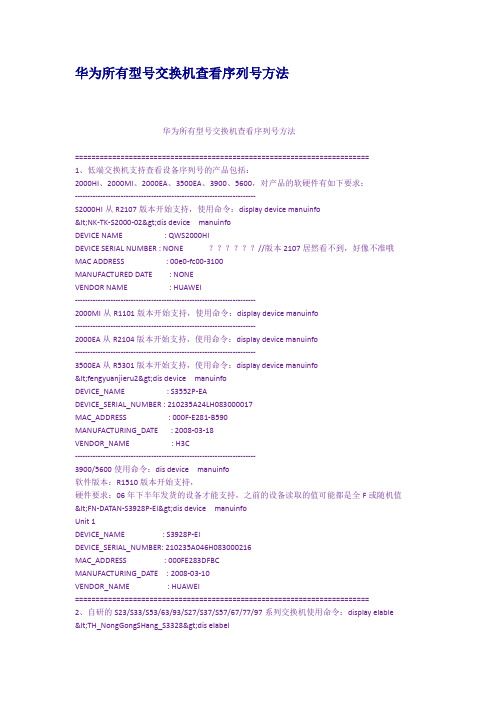
VENDOR_NAME : HUAWEI
=======================================================================
2、自研的S23/S33/S53/63/93/S27/S37/S57/67/77/97系列交换机使用命令:display elable
1、低端交换机支持查看设备序列号的产品包括:
2000HI、2000MI、2000EA、3500EA、3900、5600,对产品的软硬件有如下要求:
-----------------------------------------------------------------------
S2000HI从R2107版本开始支持,使用命令:display device manuinfo
(2)SC0000361369
[ZQ-S8512-hidecmd]_display sninfo slotnum 1
Board SN is 03A03RA067000037
YEAR : 06
MONTH : 7
第一行为序列号,第二行为制造的年份,第三行为制作的月份。
=======================================================================
XB6 系列 PROFINET 插片式 I O 用户手册-1690782667.3704727说明书

5.1
安装指南....................................................................................................................................................... 16
2.1.1 耦合器命名规则........................................................................................................................................3
3.5
模拟量参数 .....................................................................................................................................................8
5.4
外形尺寸....................................................................................................................................................... 22
3
产品参数 ........................................................................................................................................................................6
工业触摸控制系列

分辨率亮度色彩对比度触摸系统主板CPU内存储存体芯片组SATA LAN Audio 储存体I/O接口扩展总线产品尺寸分辨率亮度色彩对比度触摸系统视频输入PC触摸电脑系列产品参数系统参数型号:PC6-126、1I/OYL触摸显示器系列型号:YL5-105、1产品参数端口工作环境操作温度储存温度操作湿度防震性能资格证书获证证书电源器电源输入电源输出产品规格材料结构安装方式净重/毛重体积规格 LWH体积规格 LWHQC触摸电脑系列型号:QC6-106、1产品参数产品尺寸分辨率亮度色彩对比度触摸系统主板CPU内存系统参数主板CPU内存芯片组SATALANAudio储存体I/OI/O接口扩展总线扩展总线QM触摸显示器系列型号:QM5-105、1产品参数产品尺寸分辨率亮度色彩对比度触摸系统端口视频输入工作环境操作温度储存温度操作湿度防震性能资格证书获证证书电源器电源输入电源输出产品规格材料结构安装方式净重/毛重体积规格 LWHMD迷你工控机型号:MD6-GK0104系统参数主板CPU内存芯片组SATALANAudioI/OI/O接口电路等级表面硬度透 光 率单点寿命笔划寿命触点抖动时间分辨率触点抖动时间温度温度湿度线性玻璃厚度操作压力玻璃种类电路等级表面硬度单点寿命笔划寿命触点抖动时间分辨率触点抖动时间温度温度线性操作环境MapleTouch电阻触摸屏TouchKit五线电阻触摸屏型号:Touchkit五产品参数透 光 率型号:军工高温电产品参数操作环境储存环境储存环境扩展总线玻璃厚度操作压力玻璃种类TouchKit四线电阻触摸屏型号:四线电阻式产品参数电路等级表面硬度透 光 率单点寿命笔划寿命触点抖动时间分辨率触点抖动时间操作环境温度储存环境温度线性玻璃厚度操作压力玻璃种类表面声波屏型号:表面声波性能总览构造电缆和接口位置和精度触摸点密度触摸反应力度表面耐力使用寿命预计透光率热插特性稳定性温度性能操作相对温度红外触摸屏【工作原理】红外触摸屏应的位置关系,形成一张网阻挡住某处的红外线发射接收时,此点的横竖两个方向的接收红外管接收到的红通过了解红外线的接收的变化就能知道何处进行了触摸。
N121X5-L06

TFT LCD Approval SpecificationMODEL NO.: N121X5 -L06 O2007-01-11 19:10:37 CST Approve by Dept.Mgr.(QA RA)tomy_chen(³/52720/54140/43150)DepartmentManager(QA RA)Accept2007-01-10 18:18:54 CST Approve byDirectorteren_lin(ªL K/56910/36064)Director Accept- CONTENTS -REVISION HISTORY ------------------------------------------------------- 3 1. GENERAL DESCRIPTION ------------------------------------------------------- 41.1 OVERVIEW1.2 FEATURES1.3 APPLICATION1.4 GENERAL SPECIFICATIONS1.5 MECHANICAL SPECIFICATIONS2. ABSOLUTE MAXIMUM RATINGS ------------------------------------------------------- 52.1 ABSOLUTE RATINGS OF ENVIRONMENT2.2 ELECTRICAL ABSOLUTE RATINGS2.2.1 TFT LCD MODULE2.2.2 BACKLIGHT UNIT3. ELECTRICAL CHARACTERISTICS ------------------------------------------------------- 73.1 TFT LCD MODULE3.2 BACKLIGHT UNIT4. BLOCK DIAGRAM ------------------------------------------------------- 124.1 TFT LCD MODULE4.2 BACKLIGHT UNIT5. INPUT TERMINAL PIN ASSIGNMENT ------------------------------------------------------- 135.1 TFT LCD MODULE5.2 BACKLIGHT UNIT5.3 TIMING DIAGRAM OF LVDS INPUT SIGNAL5.4 COLOR DATA INPUT ASSIGNMENT5.5 EDID DATA STRUCTURE5.6 EDID SIGNAL SPECIFICATION6. INTERFACE TIMING ------------------------------------------------------- 206.1 INPUT SIGNAL TIMING SPECIFICATIONS6.2 POWER ON/OFF SEQUENCE7. OPTICAL CHARACTERISTICS ------------------------------------------------------- 227.1 TEST CONDITIONS7.2 OPTICAL SPECIFICATIONS8. PRECAUTIONS ------------------------------------------------------- 25 8.1 HANDLING PRECAUTIONS8.2 STORAGE PRECAUTIONS8.3 OPERATION PRECAUTIONS9. PACKING ------------------------------------------------------- 26 9.1 CARTON9.2 PALLET10. DEFINITION OF LABELS ------------------------------------------------------- 2710.1 CMO MODULE LABEL10.2 CARTON LABELREVISION HISTORYVersion Date Page(New)Section DescriptionVer 1.0 Ver 2.0Ver 3.0 Ver 3.1 Sep. 29. ‘06Nov. 13. ‘06Nov. 15. ‘06Nov.22. ‘06Jan.10. ‘07AllAll920214722279AllAll3.26.16.21.43.17.17.2103.2Preliminary Specification was first issued.Approval Specification was first issueBacklight unit Power Consumption TEST condition change 6mA to 5mA.Lamp Life Time change Min10,000H(6.0mA) to 12,000H(5.0mA).Lamp Current change Min 3.0mA Typ 6.0mA to Min no Spec Typ 5.0mA.Operating Frequency change Min50KHz to Min 45kHz.Lamp Turn On Voltage change MAx 1340V 0¢J to Max 1300V 0¢J.DCLK Frequency change Min 50MHz to Min 43.3MHz.Modify Power on/off sequence.Modify the surface treatmentfrom 41% to 42% (Haze value)Modify power supply current.Modify the inverter current from 6mA to 5mAModify the Wx ..Modify DEFINITION OF LABELSModify 3.2 note (1) lamp wire color1. GENERAL DESCRIPTION1.1 OVERVIEWN121X5 -L06 is a 12.1” TFT Liquid Crystal Display module with single CCFL Backlight unit and 20 pinsLVDS interface. This module supports 1024 x 768 XGA mode and can display 262,144 colors. The optimumviewing angle is at 6 o’clock direction. The inverter module for Backlight is not built in.1.2 FEATURES- Thin and light weight- XGA (1024 x 768 pixels) resolution- DE (Data Enable) only mode- 3.3V LVDS (Low Voltage Differential Signaling) interface with 1 pixel/clock- Support EDID Structure Version 1 Revision 31.3 APPLICATION- TFT LCD Notebook1.4 GENERAL SPECIFICATI0NSUnitNote Item SpecificationActive Area 245.76 (H) X 184.32 (V) mm(1)Bezel Opening Area 250.5 (H) x 188.9 (V) mmDriver Element a-si TFT active matrix - -Pixel Number 1024 x R.G.B. x 768 pixel -Pixel Pitch 0.24 (H) x 0.24 (V) mm -Pixel Arrangement RGB vertical stripe - -Display Colors 262,144 color -Transmissive Mode Normally white - -Surface Treatment Hard coating (2H), Anti-glare (Haze 42 %) - -1.5 MECHANICAL SPECIFICATIONSNoteUnitTyp.Item Min.Max.Horizontal(H) 260.5 261 261.5 mmModule Size(1)Vertical(V) 197.5 198 198.5 mmmmDepth(D) -- 4.7 5.0g-270Weight --260Note (1) Please refer to the attached drawings for more information of front and back outline dimensions.Note (2) Connector mounting position2. ABSOLUTE MAXIMUM RATINGS2.1 ABSOLUTE RATINGS OF ENVIRONMENTValueItem Symbol Min. Max.Unit NoteStorage Temperature T ST -20 +60 ºC (1) Operating Ambient Temperature T OP 0 +50 ºC (1), (2) Shock (Non-Operating) S NOP - 210/50 G (3),(5) Vibration (Non-Operating) V NOP - 1.5 G (4), (5) Note (1) Temperature and relative humidity range is shown in the figure below. (a) 90 %RH Max. (Ta 40ºC).(b) Wet-bulb temperature should be 39 ºC Max. (Ta > 40 ºC).(c) No condensation.Note (2) The temperature of panel surface should be 0 ºC Min. and 50 ºC Max.Note (3) 1 time for ± X, ± Y , ± Z. for Condition (210G / 3ms) is half Sine Wave, Condition (50G / 18ms) isRectangle Wave,Note (4) 10 ~ 200 Hz, 0.5 Hr / Cycle, 1 cycles for each X, Y , Z.Note (5) At testing Vibration and Shock, the fixture in holding the module has to be hard and rigid enoughso that the module would not be twisted or bent by the fixture. The fixing condition is shown as below:Side Mount Fixing ScrewStageBracketGap=2mmAt Room Temperature2.2 ELECTRICAL ABSOLUTE RATINGS2.2.1 TFT LCD MODULEValueUnit Note Item SymbolMin. Max.Power Supply Voltage Vcc -0.3 +4.0 V(1)Logic Input Voltage V IN -0.3 Vcc+0.3 V2.2.2 BACKLIGHT UNITValueItem SymbolUnit NoteMin. Max.V RMS(1), (2), I L = (6.0) mA Lamp Voltage V L - 2.5KmA RMSLamp Current I L - 6.5(1), (2)Lamp Frequency F L - 80 KHzNote (1) Permanent damage to the device may occur if maximum values are exceeded. Function operation should be restricted to the conditions described under Normal Operating Conditions.Note (2) Specified values are for lamp (Refer to Section 3.2 for further information).3. ELECTRICAL CHARACTERISTICS3.1 TFT LCD MODULEValueParameter SymbolMin. Typ. Max.Unit NotePower Supply Voltage Vcc 3.0 3.3 3.6 V - Permissive Ripple Voltage V RP 50 mV - Rush Current I RUSH 1.5 A (2) Initial Stage Current I IS 1.0 A (2)White 240 280 mA (3)aPower Supply Current Black Icc290 340 mA (3)bLVDS Differential Input High Threshold V TH(LVDS) +100 mV(5),V CM=1.2VLVDS Differential Input Low Threshold V TL(LVDS)-100 mV(5)V CM =1.2VLVDS Common Mode Voltage V CM 1.125 1.375 V (5) LVDS Differential Input Voltage |V ID | 100 600 mV (5) Terminating Resistor R T 100 Ohm Power per EBL WG P EBL - 2.6 - W (4) Note (1) The ambient temperature is Ta = 25 ± 2 ºC. Note (2) I RUSH : the maximum current when VCC is rising I IS : the maximum current of the first 100ms after power-onMeasurement Conditions: Shown as the following figure. Test pattern: black.+3.3VNote (3) The specified power supply current is under the conditions at Vcc = 3.3 V, Ta = 25 ± 2 ºC, f v = 60Hz, whereas a power dissipation check pattern below is displayed.Note(4) The specified power are the sum of LCD panel electronics input power and the inverter inputpower. Test conditions are as follows. (a) Vcc = 3.3 V, Ta = 25 ± 2 ºC, f v = 60 Hz,(b) The pattern used is a black and white 32 x 36 checkerboard, slide #100 from the VESA file“Flat Panel Display Monitor Setup Patterns”, FPDMSU.ppt.(c) Luminance: 60 nits.(d) The inverter used is provided from Sumida. Please contact them for detail information. CMOdoesn’t provide the inverter in this product.Note (5) The parameters of LVDS signals are defined as the following figures.Active Areaa. White PatternActive Areab. Black Pattern0V V CM|Single Ended0V |V TH(LVDS)V TL(LVDS)Differential3.2 BACKLIGHT UNIT Ta = 25 ± 2 ºCValueParameter Symbol Min. Typ. Max.Unit NoteLamp Input Voltage V L - 624 - V RMS I L = 5.0 mA Lamp Current I L - 5.0 - mA RMS (1),(7)- - 1170 (25 oC)V RMS (2)Lamp Turn On Voltage V S - -1300 (0oC)V RMS (2) Operating Frequency F L 45 - 80 KHz (3) Power Consumption P L - 3.12 W (4), I L = 5.0 mA Lamp Life Time L BL 12,000 - - Hrs (5)Note (1) Lamp current is measured by utilizing a high frequency current meter as shown below:Note (2) The voltage shown above should be applied to the lamp for more than 1 second after startup.Otherwise the lamp may not be turned on.Note (3) The lamp frequency may generate interference with horizontal synchronous frequency from thedisplay, and this may cause line flow on the display. In order to avoid interference, the lamp frequency should be detached from the horizontal synchronous frequency and its harmonics as far as possible.Note (4) P L = I L V LNote (5) The lifetime of lamp is defined as the time when it continues to operate under the conditions at Ta= 25 2 o C and I L = 5.0 mA RMS until one of the following events occurs: (a) When the brightness becomes 50% of its original value.(b) When the effective ignition length becomes ¡ 80% of its original value. (Effective ignitionlength is defined as an area that the brightness is less than 70% compared to the center point.)Note (6) The waveform of the voltage output of inverter must be area-symmetric and the design of theinverter must have specifications for the modularized lamp. The performance of the Backlight, such as lifetime or brightness, is greatly influenced by the characteristics of the DC-AC inverter for the lamp. All the parameters of an inverter should be carefully designed to avoid generating too much current leakage from high voltage output of the inverter. When designing or ordering the inverter please make sure that a poor lighting caused by the mismatch of the Backlight and the inverter (miss-lighting, flicker, etc.) never occurs. If the above situation is confirmed, the module should be operated in the same manners when it is installed in your instrument.The output of the inverter must have symmetrical (negative and positive) voltage waveform and symmetrical current waveform.(Unsymmetrical ratio is less than 10%) Please do not use the inverter,which has unsymmetrical voltage and unsymmetrical current and spike wave. Lamp frequency may produce interface with horizontal synchronous frequency and as a result this may cause beat on the display. Therefore lamp frequency shall be as away possible from the horizontal synchronous frequency and from its harmonics in order to prevent interference.Requirements for a system inverter design, which is intended to have a better display performance, a better power efficiency and a more reliable lamp. It shall help increase the lamp lifetime and reduce its leakage current.a. The asymmetry rate of the inverter waveform should be 10% below;b. The distortion rate of the waveform should be within 2 ± 10%;c. The ideal sine wave form shall be symmetric in positive and negative polarities.* Asymmetry rate:| I p – I –p | / I rms * 100%* Distortion rate I p (or I –p ) / I rmsNote (7) About operating current min 2.0mA , lamp maker has some advice as belowExplanation and comparison of the kind of tone light: Lamp current wave-like by the adjustment of the current.Lamp current wave-like by the adjustment of the burst.Comparative table Method Backlight efficiency (INV¡LAMP)Tone light rate (%)Circuitrycurrent Good ( 75 % 85% )58 Complicated burst Bad ( 65 % 75% )10 EasyMethod of case that Lamp current MIN2.0mA is controlled.It is the setting of minimum 2mA (MIN) to Lamp current 6.0mA in the lamp specification. The burst is excellent for circuitry. The marker proposes that pays attention to the following contents.ON:80%4. BLOCK DIAGRAM4.1 TFT LCD MODULE4.2 BACKLIGHT UNITV EDIDDataGNDCLK Vcc5. INPUT TERMINAL PIN ASSIGNMENT5.1 TFT LCD MODULEPin Symbol Description Polarity Remark1 Vss Ground2 Vcc Power Supply +3.3 V (typical) 3 Vcc Power Supply +3.3 V (typical)4 V EDID DDC 3.3V Power DDC 3.3V Power5 NC Non-Connection6 CLK EDID DDC Clock DDC Clock7 DATA EDID DDC DataDDC Data 8 Rxin0- LVDS Differential Data Input Negative 9Rxin0+LVDS Differential Data InputPositiveR0~R5,G0-10 Vss Ground 11 Rxin1- LVDS Differential Data Input Negative 12Rxin1+LVDS Differential Data InputPositiveG1~G5,B0,B1-13 Vss Ground 14 Rxin2- LVDS Differential Data Input Negative 15 Rxin2+ LVDS Differential Data Input PositiveB2~B5,DE,Hsync,Vsync16 Vss Ground 17 CLK- LVDS Clock Data Input Negative18 CLK+ LVDS Clock Data Input PositiveLVDS Level Clock19 Vss Ground 20 Vss GroundNote (1) The first pixel is even.Note (2) Connector Part No.: HIROSE DF19L-20P-1H or equivalent Note (3) User’s connector Part No: HIROSE DF19G-20S-1C or equivalent5.2 BACKLIGHT UNITPin Symbol Description Color1 HV High Voltage White2 LV Ground BlackNote (1) Connector Part No.: JST-BHSR-02VS-1 or equivalentNote (2) User’s connector Part No.: JST-SM02B-BHSS-1-TB or equivalent5.3 TIMING DIAGRAM OF LVDS INPUT SIGNALRxin0Rxin1Rxin2CLK+5.4 COLOR DATA INPUT ASSIGNMENTThe brightness of each primary color (red, green and blue) is based on the 6-bit gray scale data input forthe color. The higher the binary input the brighter the color. The table below provides the assignment ofcolor versus data input.Data SignalRed Green Blue ColorR5R4 R3 R2R1R0G5G4G3G2G1G0B5 B4 B3 B2B1B0Basic Colors BlackRedGreenBlueCyanMagentaYellowWhite111111111111111111111111111111111111111111111111111111111111111111111111Gray Scale Of Red Red(0)/DarkRed(1)Red(2)::Red(61)Red(62)Red(63)::111::111::111::1111::111::11::::::::::::::::::::::::Gray Scale Of Green Green(0)/DarkGreen(1)Green(2)::Green(61)Green(62)Green(63)::::::::::::::111::111::111::1111::111::11::::::::::::Gray Scale Of Blue Blue(0)/DarkBlue(1)Blue(2)::Blue(61)Blue(62)Blue(63)::::::::::::::::::::::::::111::111::111::1111::111::11Note (1) 0: Low Level Voltage, 1: High Level Voltage5.5 EDID DATA STRUCTUREThe EDID (Extended Display Identification Data) data formats are to support displays as defined in the VESA Plug & Display and FPDI standards.Byte # (decimal) Byte #(hex)Field Name and CommentsValue(hex)Value(binary)0 0Header 00 00000000 1 1Header FF 11111111 2 2Header FF 11111111 3 3Header FF 11111111 4 4Header FF 11111111 5 5Header FF 11111111 6 6Header FF 11111111 7 7Header 00 00000000 8 8ID system Manufacturer Name 30 00110000 9 9Compressed ASCII AE 10101110 10 0AID Product Code (LSB) 00 00000000 11 0BID Product Code (MSB) 40 01000000 12 0CLCD Module Serial No. = 0 (If not used) 00 00000000 13 0DLCD Module Serial No. = 0 (If not used) 00 00000000 14 0ELCD Module Serial No. = 0 (If not used) 00 00000000 15 0FLCD Module Serial No. = 0 (If not used) 00 00000000 16 10Week of Manufacture 30 00110000 17 11Year of Manufacture 10 00010000 18 12EDID Structure version 01 00000001 19 13EDID Revision 03 00000011 20 14Video Input Definition = Digital I/P,non TMDS CRGB 80 10000000 21 15Max H image size(¢Q) = 30.5Q19 00011001 22 16Max V image size(¢Q) = 18.3Q12 00010010 23 17Display gamma 78 01111000 24 18Feature support(DPMS) = Active off, RGB Color EA 11101010 25 19Red/Green low Bits FE 11111110 26 1ABlue/White Low Bits 60 01100000 27 1BRed X 95 10010101 28 1CRed Y 55 01010101 29 1DGreen X 51 01010001 30 1EGreen Y 87 10000111 31 1FBlue X 26 00100110 32 20Blue Y 22 00100010 33 21White X 50 01010000 34 22White Y 54 01010100 35 23Established Timing I = 00h(If not used) 21 00100001 36 24Established Timing II = 00h(If not used) 08 00001000 37 25Manufacturer's Timings = 00h(If not used) 00 00000000 38 26Standard Timing Identification 1 was not used 01 00000001 39 27Standard Timing Identification 1 was not used 01 00000001 40 28Standard Timing Identification 2 was not used 01 00000001 41 29Standard Timing Identification 2 was not used 01 00000001Byte # (decimal) Byte #(hex)Field Name and CommentsValue (hex) Value(binary) 42 2A Standard Timing Identification 3 was not used 01 00000001 43 2B Standard Timing Identification 3 was not used 01 00000001 44 2C Standard Timing Identification 4 was not used 01 00000001 45 2D Standard Timing Identification 4 was not used 01 00000001 46 2E Standard Timing Identification 5 was not used 01 00000001 47 2F Standard Timing Identification 5 was not used 01 00000001 48 30 Standard Timing Identification 6 was not used 01 00000001 49 31 Standard Timing Identification 6 was not used 01 00000001 50 32 Standard Timing Identification 7 was not used 01 00000001 51 33 Standard Timing Identification 7 was not used 01 00000001 52 34 Standard Timing Identification 8 was not used 01 00000001 53 35 Standard Timing Identification 8 was not used 01 00000001 54 36 Pixel Clock/10,000 (LSB) 28 00101000 55 37 Pixel Clock/10,000 (MSB) / 15 00010101 56 38 Horizontal Active 00 00000000 57 39 Horizontal Blanking 40 01000000 58 3A Horizontal Active : Horizontal Blanking 41 01000001 59 3B Vertical Avtive 00 00000000 60 3C Vertical Blanking 26 00100110 61 3D Vertical Active : Vertical Blanking 30 00110000 62 3E Horizontal Sync. Offset 18 00011000 63 3F Horizontal Sync Pulse Width 88 10001000 64 40 Vertical Sync Offset : Sync Width 36 00110110 65 41 Horizontal Vertical Sync Offset/Width upper 2bits = 0 00 00000000 66 42 Horizontal Image Size F6 11110110 67 43 Vertical Image Size B8 10111000 68 44 Horizontal & Vertical Image Size (upper 4bit) 00 00000000 69 45 Horizontal Border = 0 00 00000000 70 46 Vertical Border = 000 00000000 71 47Non-interlaced,Normal display,no stereo,Digital separate sync,H/V pol negatives18 00011000 72 48 Pixel Clock/10,000 (LSB) 40HzED 11101101 73 49 Pixel Clock/10,000 (MSB) / 40Hz 10 00010000 74 4A Horizontal Active 00 00000000 75 4B Horizontal Blanking 40 01000000 76 4C Horizontal Active : Horizontal Blanking 41 01000001 77 4D Vertical Avtive 00 00000000 78 4E Vertical Blanking 26 00100110 79 4F Vertical Active : Vertical Blanking 30 00110000 80 50 Horizontal Sync. Offset 18 00011000 81 51 Horizontal Sync Pulse Width 88 10001000 82 52 Vertical Sync Offset : Sync Width 36 00110110 83 53 Horizontal Vertical Sync Offset/Width upper 2bits = 0 00 00000000 84 54 Horizontal Image Size F6 11110110 85 55 Vertical Image SizeB9 10111001Byte # (decimal) Byte #(hex)Field Name and CommentsValue (hex) Value(binary) 86 56 Horizontal & Vertical Image Size (upper 4bit) 00 00000000 87 57 Horizontal Border = 0 00 00000000 88 58 Vertical Border = 000 00000000 89 59Non-interlaced,Normal display,no stereo,Digital separate sync,H/V pol negatives18 00011000 90 5A Detailed Timing Descriptor #300 00000000 91 5B 00 00000000 92 5C 00 00000000 93 5D 0F 00001111 94 5E 00 00000000 95 5F (Horizontal active pixel /8)-31 61 01100001 96 60 Image Aspect Ratio(16:10) 43 01000011 97 61 Low Refresh Rate #1(50Hz) 32 00110010 98 62 (Horizontal active pixel /8)-31 61 01100001 99 63 Image Aspect Ratio(16:10) 43 01000011 100 64 Low Refresh Rate #2(40Hz) 28 00101000 101 65 Brightness(1/10nit) 0F 00001111 102 66 Feature flag(TN mode) 01 00000001 103 67 Reserved 00h 00 00000000 104 68 EISA manufacturer code(3 Character ID) 0D 00001101 105 69 Compressed ASCII AF 10101111 106 6A Panel Supplier Reserved - Product code 07 00000111 107 6B (Hex, LSB first) 14 00010100 108 6C Detailed Timing Descriptor #4 00 00000000 109 6D 00 00000000 110 6E 00 00000000 111 6F FE 11111110 112 70 00 00000000 113 71 (Supplier S/N) 4E 01001110 114 72 (Supplier S/N) 31 00110001 115 73 (Supplier S/N) 32 00110010 116 74 (Supplier S/N) 31 00110001 117 75 (Supplier S/N) 58 01011000 118 76 (Supplier S/N) 35 00110101 119 77 (Supplier S/N) 2d 00101101 120 78 (Supplier S/N) 4C 01001100 121 79 (Supplier S/N) 30 00110000 122 7A (Supplier S/N) 36 00110110 123 7B (Supplier S/N) 20 00100000 124 7C (Supplier S/N) 20 00100000 125 7D (Supplier S/N) 20 00100000 126 7E Extension flag = 00 00 00000000 127 7F ChecksumED 111011015.6 EDID SIGINAL SPECIFICATION(1) EDID PowerParameter Symbol Conditions Min. Typ. Max. UnitPower supply voltage Vcc ReadOperation 2.2 — 5.5 V(2) DC characteristicsSymbol Min. Max. Unit IndexHigh Voltage VIH 0.7V CC— VSCL, SDAterminal input voltage Low Voltage VIL — 0.3VCC V Hysteresis Voltage VHYS 0.05 VCC— VOutput Voltage VOL1VOL2—0.40.6VIOL=3mA, CC=2.5VIOL=6mA, CC=2.5VInput Leak current (Vin =0.1V~VCC) ILI-10-101050uAWP=VSSWP=VCCOutput Leak current ILO -10 10 uA Vout =0.1V~VCC, WP=VSSTerminal capacity(Input, Output) Cin, Cout— 10 pFVCC=5.0VTa=250C, Fclk=1.0MHzOperating current ICC WriteICC Read—31mAVCC=5.5V,SCL=400KHzStillness current(SDA=SCL=VCC) (WP=VSS,A0,A1,A2=VSS) ICCS —30100uAVCC=3.0VVCC=5.5V(3) AC characteristics (VCC=2.5~5.5V standard operation mode)VCC=2.5V-5.5V (Standard operationmode) VCC=4.5V-5.5V (High-speedoperationmode)Item SymbolMin. Max. Min.Max.Unit Index Clock frequency Fclk — 100 — 400 KHzClock High Time THIGH 4000 — 900 — nsClock Low Time TLOW 4700 — 1300— nsSDA, SCL falling time TR — 1000 — 300 nsSDA, SCL rising time TF — 300 — 300 nsSTART hold time THD:STA4000 — 600—nsSTART setup time TSU:STA4700 — 600—nsData input hold time THD:Data0 — 0—nsData input setup time TSU:Data250 — 100—nsSTOP setup time TSU:STO4700 — 600—nsOutput decision time from aclock TAA — 3500 100900nsBus free time TBUF 4700 — 1300— nsRising time of Min VIH, VIL TOF — 250 20 250 ns CB¡100pF Spike oppression TSP — 50 — 50 nsA write-in cycle time TWR — 10 — 10 ms Byte and pagemodeThe number of times of datarewriting — 1M — 1M—cyclesVCC=5.0VTa=250C,6. INTERFACE TIMING6.1 INPUT SIGNAL TIMING SPECIFICATIONSThe input signal timing specifications are shown as the following table and timing diagram .Signal Item Symbol Min. Typ. Max. Unit Note DCLK Frequency 1/Tc 43.3 65 68 MHz -Vertical Total Time TV 771 806 850 TH - Vertical Addressing Time TVD 768 768 768 TH-Horizontal Total Time TH 120013441500 Tc - DEHorizontal Addressing Time THD 102410241024 Tc -INPUT SIGNAL TIMING DIAGRAMDCLKDEDE DATA6.2 POWER ON/OFF SEQUENCETiming Specifications:t1¡ 10 msec0 < t2 50 msec0 < t3 t4 ¡ 150 msec t5 ¡200 msec t6 ¡0 msec t7 10 msec (given by system) Note (1) Please follow the power on/off sequence described above. Otherwise, the LCD module might bedamaged.Note (2) Please avoid floating state of interface signal at invalid period. When the interface signal is invalid, besure to pull down the power supply of LCD Vcc to 0 V.Note (3) The Backlight inverter power must be turned on after the power supply for the logic and theinterface signal is valid. The Backlight inverter power must be turned off before the power supplyfor the logic and the interface signal is invalid.Note (4) Sometimes some slight noise shows when LCD is turned off (even backlight is already off). Toavoid this phenomenon, we suggest that the Vcc falling time had better to follow 5¡t7¡300 ms.- Power Supply for LCD, Vcc - LVDS Interface - Power for LampRestart Power On Power Off 0V 0V7. OPTICAL CHARACTERISTICS7.1 TEST CONDITIONS Item Symbol Value UnitAmbient Temperature Ta 25±2 o CAmbient Humidity Ha 50±10 %RHSupply Voltage V CC 3.3 VInput Signal According to typical value in "3. ELECTRICAL CHARACTERISTICS"Inverter Current I L 5.0 mAInverter Driving Frequency F L 61 KHzInverter Sumida-H05-4915 The measurement methods of optical characteristics are shown in Section 7.2. The following itemsshould be measured under the test conditions described in Section 7.1 and stable environment shown inNote (6).7.2 OPTICAL SPECIFICATIONS ItemSymbol Condition Min. Typ. Max. Unit Note Contrast Ratio CR 180 300 - - (2), (5)T R - 5 10 ms Response Time T F -11 16 ms (3) Central Luminance of White L AVE 120 150 - cd/m 2(4), (5)5pts 1.25 - White Variation δW 13pts 1.54 (5), (6)Rx 0.595 - Red Ry 0.338 - Gx 0.320 - Green Gy 0.533 - Bx 0.150 - Blue By TYP -0.030.135 TYP +0.03 - Wx 0.2850.313 0.341 - ColorChromaticity White Wyθx =0°, θY =0° Viewing Normal Angle 0.3090.329 0.349 - θx + 40 45 - Horizontal θx - 40 45 - θY + 15 20 - Viewing Angle Vertical θY -CR ≥10 40 45 - Deg. (1)Note (1)Definition of Viewing Angle (θx, θy):Note (2) Definition of Contrast Ratio (CR):The contrast ratio can be calculated by the following expression.Contrast Ratio (CR) = L63 / L0L63: Luminance of gray level 63L 0: Luminance of gray level 0CR = CR (5)CR (X) is corresponding to the Contrast Ratio of the point X at Figure in Note (7).Note (3) Definition of Response Time (T R , T F ):Note (4) Definition of Average Luminance of White (L AVE ):Measure the luminance of gray level 63 at 5 pointsL AVE = [L (1)+ L (2)+ L (3)+ L (4)+ L (5)] / 5 L (x) is corresponding to the luminance of the point X at Figure in Note (6)100%90%10%0%OpticalNote (5) Measurement Setup:The LCD module should be stabilized at given temperature for 20 minutes to avoid abrupttemperature change during measuring. In order to stabilize the luminance, the measurementshould be executed after lighting Backlight for 20 minutes in a windless room.Note (6) Definition of White Variation (δW):Measure the luminance of gray level 63 at 13 pointsδW 5p = Maximum [L (1), L (2), L (3), L (4), L (5)] / Minimum [L (1), L (2), L (3), L (4), L (5)]δW 13p = Maximum [L (1) ~ L (13)] / Minimum [L (1) ~ L (13)]Photometer (CA210, CS-1000) Field of View = 2º500 mm LCD Module LCD Panel Center of the Screen Light Shield Room (Ambient Luminance < 2 lux)V e r t i c a l L i n e: Test PointX=1 to 13Horizontal Line。
- 1、下载文档前请自行甄别文档内容的完整性,平台不提供额外的编辑、内容补充、找答案等附加服务。
- 2、"仅部分预览"的文档,不可在线预览部分如存在完整性等问题,可反馈申请退款(可完整预览的文档不适用该条件!)。
- 3、如文档侵犯您的权益,请联系客服反馈,我们会尽快为您处理(人工客服工作时间:9:00-18:30)。
TFT LCD Preliminary Specification MODEL NO.: M156B1-L01Customer:Approved by:Note: For Reference OnlyLiquid Crystal Display DivisionQRA Division OA Head DivisionApproval Approval- CONTENTS -REVISION HISTORY (3)1. GENERAL DESCRIPTION (4)1.1 OVERVIEW1.2 FEATURES1.3 APPLICATION1.4 GENERAL SPECIFICATIONS1.5 MECHANICAL SPECIFICATIONS2. ABSOLUTE MAXIMUM RATINGS (5)2.1 ABSOLUTE RATINGS OF ENVIRONMENT2.2 ELECTRICAL ABSOLUTE RATINGS2.2.1 TFT LCD MODULE2.2.2 BACKLIGHT UNIT3. ELECTRICAL CHARACTERISTICS (7)3. 1.1 TFT LCD MODULE3.1.2 Vcc Power Dip Condition:3.2 BACKLIGHT UNIT4. BLOCK DIAGRAM (11)4.1 TFT LCD MODULE4.2 BACKLIGHT UNIT5. INPUT TERMINAL PIN ASSIGNMENT (12)5.1 TFT LCD MODULE5.2 LVDS DATA MAPPING TABLE5.3 BACKLIGHT UNIT5.4 COLOR DATA INPUT ASSIGNMENT6. INTERFACE TIMING (15)6.1 INPUT SIGNAL TIMING SPECIFICATIONS6.2 POWER ON/OFF SEQUENCE7. OPTICAL CHARACTERISTICS (17)7.1 TEST CONDITIONS7.2 OPTICAL SPECIFICATIONS8. PACKAGING (21)8.1 PACKING SPECIFICATIONS8.2 PACKING METHOD9. DEFINITION OF LABELS (23)10. PRECAUTIONS (24)10.1 ASSEMBLY AND HANDLING PRECAUTIONS10.2 SAFETY PRECAUTIONS11. MECHANICAL CHARACTERISTICS (25)REVISION HISTORYVersion Date Section DescriptionVer 1.0 Sep. 28, 07’ - M156B1-L01 Preliminary specification was first issued.1. GENERAL DESCRIPTION1.1 OVERVIEWM156B1-L01 is a 15.6” TFT Liquid Crystal Display module with 2 CCFL Backlight unit and 30pin 1ch-LVDS interface. This module supports 1366 x 768 WXGA mode and can display up to 16.7M colors. The inverter module for Backlight is not built in.1.2 FEATURES- Contrast ratio 500:1 - Response time 8ms. - Brightness 250nits- Color saturation NTSC 65%. - WXGA (1366 x 768 pixels) resolution. - DE (Data Enable) only mode.- LVDS (Low Voltage Differential Signaling) interface. - RoHS compliance. - TCO’03 compliance.1.3 APPLICATION- TFT LCD Monitor1.4 GENERAL SPECIFICATI0NSItem SpecificationUnit Note Active Area 344.232(H) × 193.536(V) (15.6” diagonal)mm Bezel Opening Area 347.5(H)x196.8(V) mm (1) Driver Element a-Si TFT active matrix - - Pixel Number 1366 x R.G.B. x 768 pixel - Pixel Pitch 0.252 (H) x 0.252 (V) mm - Pixel Arrangement RGB vertical stripe- - Display Colors 16.7Mcolor - Transmissive Mode Normally White- - Surface TreatmentAG type, 3H hard coating, Haze 25--1.5 MECHANICAL SPECIFICATIONSItemMin. Typ. Max. Unit Note Horizontal(H)363.3 363.8 364.3 mm Vertical(V)215.4 215.9 216.4 mm Module Size Depth(D)13.8 14.3 14.8 mm (1) Weight-1300g-Note (1) Please refer to the attached drawings for more information of front and back outline dimensions.2. ABSOLUTE MAXIMUM RATINGS2.1 ABSOLUTE RATINGS OF ENVIRONMENTValueItemSymbol Min. Max. Unit Note Storage TemperatureT ST -20 60 ºC(1) Operating Ambient TemperatureT OP 0 50 ºC(1), (2) Shock (Non-Operating) S NOP - 50 G (3), (5) Vibration (Non-Operating) V NOP-1.5G(4), (5)Note (1) Temperature and relative humidity range is shown in the figure below.(a) 90 %RH Max. (Ta Љ 40 ºC).(b) Wet-bulb temperature should be 39 ºC Max. (Ta > 40 ºC).(c) No condensation.Note (2) The temperature of panel display surface area should be 0 ºC Min. and 60 ºC Max.Note (3) 11ms, half sine wave, 1 time for ± X, ± Y , ± Z. Note (4) 10 ~ 300 Hz, 10min/cycle, 3 cycles each X, Y , Z.Note (5) At testing Vibration and Shock, the fixture in holding the module has to be hard and rigid enoughso that the module would not be twisted or bent by the fixture. The fixing condition is shown as below:2.2 ELECTRICAL ABSOLUTE RATINGS 2.2.1 TFT LCD MODULEValueItemSymbol Min. Max. Unit Note Power Supply Voltage Vcc-0.3+6.0V(1)2.2.2 BACKLIGHT UNITValueItem Symbol Min. Max. UnitNoteLamp Voltage V L TBD TBD V RMS (1), (2)Lamp Current I L (3) (8) mA RMS Lamp FrequencyF L(50)(60)KHz(1), (2) also see page.10Note(7) Note (1) Permanent damage to the device may occur if maximum values are exceeded. Function operationshould be restricted to the conditions described under Normal Operating Conditions.Note (2) Specified values are for lamp (Refer to 3.2 for further information).3. ELECTRICAL CHARACTERISTICS3.1.1 TFT LCD MODULETa = 25 ± 2 ºCValue ParameterSymbol Min. Typ. Max. Unit Note Power Supply VoltageVcc 4.5 5.0 5.5 V - Ripple Voltage V RP - - 100 mV - Rush CurrentI RUSH (1.5) A(2) White(0.3) (0.35) A (3)a Black(0.35) (0.41) A (3)b Power Supply Current Vertical Stripe- - - (0.4) (0.43) A (3)c LVDS differential input voltage Vid 100 - 600 mV LVDS common input voltage Vic-1.2-VNote (1) The module should be always operated within above ranges.Note (2) Measurement Conditions:Vcc rising time is 470µsSWVcc+5.0VNote (3) The specified power supply current is under the conditions at Vcc = 5.0 V, Ta = 25 ± 2 ºC, f v = 60Hz, whereas a power dissipation check pattern below is displayed.3.1.2 Vcc Power Dip Condition:Dip condition: ms Td V Vcc V 20,5.40.4≤≤≤Active Areaa. White PatternActive Area c. Vertical Stripe PatternActive Areab. Black Pattern3.2 BACKLIGHT UNIT Ta = 25 ± 2 ºCValue Parameter Symbol Min. Typ. Max. UnitNote Lamp Input Voltage V L (560) (660) (760) V RMS I L = 7.0 mALamp Current I L (3.0) (7.0) (8.0) mA RMS (1) (1520 (0)к) V RMS (2) Lamp Turn On Voltage V S (1490 (25)к) V RMS(2) Operating Frequency F L (50) (55) (60) KHz (3)(7) Lamp Life Time L BL 50,000 Hrs (5), I L = 7.0mA Power ConsumptionP L(9.24)W(4), I L= 7.0 mANote (1) Lamp current is measured by current amplify & oscilloscope as shown below:Current Amplify: Tektronix TCPA300 Current probe: Tektronix TCP312 Oscilloscope: TDS3054BNote (2) The voltage that must be larger than Vs should be applied to the lamp for more than 1 secondafter startup. Otherwise, the lamp may not be turned on normally.Note (3) The lamp frequency may produce interference with horizontal synchronization frequency from thedisplay, which might cause line flow on the display. In order to avoid interference, the lamp frequency should be detached from the horizontal synchronization frequency and its harmonics as far as possible.Note (4) P L = I L ͪ V L ͪ 2 (for 2 lamps)Note (5) The lifetime of lamp can be defined as the time in which it continues to operate under the conditionTa = 25 ̈́2 o C and I L = 7.0 mArms until one of the following events occurs: (a) When the brightness becomes Љ 50% of its original value.(b) When the effective ignition length becomes Љ 80% of its original value.(The effective ignition length is a scope that luminance is over 80% of that at the center point.) Note (6) The waveform of the voltage output of inverter must be area-symmetric and the design of theinverter must have specifications for the modularized lamp. The performance of the Backlight, such as lifetime or brightness, is greatly influenced by the characteristics of the DC-AC inverter for the lamp. All the parameters of an inverter should be carefully designed to avoid producing too much current leakage from high voltage output of the inverter. When designing or ordering theinverter please make sure that a poor lighting caused by the mismatch of the Backlight and the inverter (miss-lighting, flicker, etc.) never occurs. If the above situation is confirmed, the module should be operated in the same manners when it is installed in your instrument.The output of the inverter must have symmetrical (negative and positive) voltage waveform and symmetrical current waveform.(Unsymmetrical ratio is less than 10%) Please do not use the inverter which has unsymmetrical voltage and unsymmetrical current and spike wave. Lamp frequency may produce interface with horizontal synchronous frequency and as a result this may cause beat on the display. Therefore lamp frequency shall be as away possible from the horizontal synchronous frequency and from its harmonics in order to prevent interference.Requirements for a system inverter design, which is intended to have a better display performance, a better power efficiency and a more reliable lamp. It shall help increase the lamp lifetime and reduce its leakage current.a. The asymmetry rate of the inverter waveform should be 10% below;b. The distortion rate of the waveform should be within Ѕ2 ± 10%;c. The ideal sine wave form shall be symmetric in positive and negative polaritiesNote (7) 50~60KHz, the frequency range can guarantee the optical and electrical characteristics; 40~80KHzthe frequency range will not effect the Lifetime and reliability characteristics.* Asymmetry rate:| I p – I –p | / I rms * 100%* Distortion rate I p (or I –p ) / I rms4. BLOCK DIAGRAM4.1 TFT LCD MODULE4.2 BACKLIGHT UNIT5. INPUT TERMINAL PIN ASSIGNMENT5.1 TFT LCD MODULEPin Name Description1 NC Not connection, this pin should be open.2 NC Not connection, this pin should be open.3 NC Not connection, this pin should be open.4 GND Ground5 RX0- Negative LVDS differential data input. Channel 06 RX0+ Positive LVDS differential data input. Channel 07 GND Ground8 RX1- Negative LVDS differential data input. Channel 19 RX1+ Positive LVDS differential data input. Channel 110 GND Ground11 RX2- Negative LVDS differential data input. Channel 212 RX2+ Positive LVDS differential data input. Channel 213 GND Ground14 RXCLK- Negative LVDS differential clock input.15 RXCLK+ Positive LVDS differential clock input.16 GND Ground17 RX3- Negative LVDS differential data input. Channel 318 RX3+ Positive LVDS differential data input. Channel 319 GND Ground20 NC Not connection, this pin should be open.21 NC Not connection, this pin should be open.22 NC Reserved. (For internal test used)23 GND Ground24 GND Ground25 GND Ground26 VCC +5.0V power supply27 VCC +5.0V power supply28 VCC +5.0V power supply29 VCC +5.0V power supply30 VCC +5.0V power supplyNote (1) Connector Part No.: STM MSAKT2407P30A or STARCONN 093G30-B0001A5.2 LVDS mapping tableLVDS output D7 D6 D4 D3 D2 D1 D0 LVDS Channel 0Data order G0 R5 R4 R3 R2 R1 R0LVDS output D18 D15 D14 D13 D12 D9 D8 LVDS Channel 1Data order B1 B0 G5 G4 G3 G2 G1LVDS output D26 D25 D24 D22 D21 D20 D19 LVDS Channel 2Data order DE NA NA B5 B4 B3 B2LVDS output D23 D17 D16 D11 D10 D5 D27 LVDS Channel 3Data order NA B7 B6 G7 G6 R7 R6 5.3 BACKLIGHT UNIT:Pin Symbol Description Remark1 HV High Voltage Pink2 LV Low Voltage White Note (1) Connector Part No.: YEONHO 20015HS-04LB or equivalent5.4 COLOR DATA INPUT ASSIGNMENTThe brightness of each primary color (red, green and blue) is based on the 8-bit gray scale data input for the color. The higher the binary input, the brighter the color. The table below provides the assignment of color versus data input.Data SignalRedGreen Blue ColorR7 R6 R5 R4 R3 R2 R1 R0 G7 G6 G5 G4 G3 G2 G1 G0 B7 B6 B5 B4 B3 B2 B1 B0Basic ColorsBlack Red Green Blue Cyan Magenta Yellow White0 1 0 0 0 1 1 1 0 1 0 0 0 1 1 1 0 1 0 0 0 1 1 1 0 1 0 0 0 1 1 1 0 1 0 0 0 1 1 1 0 1 0 0 0 1 1 1 0 1 0 0 0 1 1 1 0 1 0 0 0 1 1 1 0 0 1 0 1 0 1 1 0 0 1 0 1 0 1 1 0 0 1 0 1 0 1 1 0 0 1 0 1 0 1 1 0 0 1 0 1 0 1 1 0 0 1 0 1 0 1 1 0 0 1 0 1 0 1 1 0 0 1 0 1 0 1 1 0 0 0 1 1 1 0 1 0 0 0 1 1 1 0 1 0 0 0 1 1 1 0 1 0 0 0 1 1 1 0 1 0 0 0 1 1 1 0 1 0 0 0 1 1 1 0 1 0 0 0 1 1 1 0 1 0 0 0 1 1 1 0 1 Gray Scale Of RedRed(0) / DarkRed(1) Red(2): :Red(253) Red(254) Red(255) 0 0 0 : : 1 1 1 0 0 0 : : 1 1 1 0 0 0 : : 1 1 1 0 0 0 : : 1 1 1 0 0 0 : : 1 1 1 0 0 0 : : 1 1 1 0 0 1 : : 0 1 1 0 1 0 : : 1 0 1 0 0 0 : : 0 0 0 0 0 0 : : 0 0 0 0 0 0 : : 0 0 0 0 0 0 : : 0 0 0 0 0 0 : : 0 0 0 0 0 0 : : 0 0 0 0 0 0 : : 0 0 0 0 0 0 : : 0 0 0 0 0 0 : : 0 0 0 0 0 0 : : 0 0 0 0 0 0 : : 0 0 0 0 0 0 : : 0 0 0 0 0 0 : : 0 0 0 0 0 0 : : 0 0 0 0 0 0 : : 0 0 0 0 0 0 : : 0 0 0 Gray Scale Of GreenGreen(0) / DarkGreen(1) Green(2): :Green(253) Green(254) Green(255) 0 0 0 : : 0 0 0 0 0 0 : : 0 0 0 0 0 0 : : 0 0 0 0 0 0 : : 0 0 0 0 0 0 : : 0 0 0 0 0 0 : : 0 0 0 0 0 0 : : 0 0 0 0 0 0 : : 0 0 0 0 0 0 : : 1 1 1 0 0 0 : : 1 1 1 0 0 0 : : 1 1 1 0 0 0 : : 1 1 1 0 0 0 : : 1 1 1 0 0 0 : : 1 1 1 0 0 1 : : 0 1 1 0 1 0 : : 1 0 1 0 0 0 : : 0 0 0 0 0 0 : : 0 0 0 0 0 0 : : 0 0 0 0 0 0 : : 0 0 0 0 0 0 : : 0 0 0 0 0 0 : : 0 0 0 0 0 0 : : 0 0 0 0 0 0 : : 0 0 0 Gray Scale Of BlueBlue(0) / DarkBlue(1) Blue(2): :Blue(253) Blue(254) Blue(255)0 0 0 : : 0 0 00 0 0 : : 0 0 00 0 0 : : 0 0 00 0 0 : : 0 0 00 0 0 : : 0 0 00 0 0 : : 0 0 00 0 0 : : 0 0 00 0 0 : : 0 0 00 0 0 : : 0 0 00 0 0 : : 0 0 00 0 0 : : 0 0 0 0 0 0 : : 0 0 00 0 0 : : 0 0 00 0 0 : : 0 0 00 0 0 : : 0 0 00 0 0 : : 0 0 00 0 0 : : 1 1 10 0 0 : : 1 1 10 0 0 : : 1 1 10 0 0 : : 1 1 10 0 0 : : 1 1 10 0 0 : : 1 1 10 0 1 : : 0 1 10 1 0 : : 1 0 1Note (1) 0: Low Level Voltage, 1: High Level VoltageDCLKDEDEDATA6. INTERFACE TIMING6.1 INPUT SIGNAL TIMING SPECIFICATIONSThe input signal timing specifications are shown as the following table and timing diagram . SignalItem Symbol Min. Typ. Max. Unit Note Frequency Fc 50.0 (76) (85) MHz - PeriodTc - 13.0 - ns High Time Tch - 4/7 - Tc - LVDS ClockLow Time Tcl - 3/7 - Tc - Setup TimeTlvs 600 - - ps - LVDS DataHold Time Tlvh 600 - - ps - Frame Rate Fr 40 60 (75) Hz Tv=Tvd+Tvb TotalTv (778) (806) (888) Th - Display Tvd 768 768 768 Th - Vertical Active Display TermBlank Tvb Tv-Tvd (38) Tv-Tvd Th - TotalTh (1446) (1560) (1936) Tc Th=Thd+Thb DisplayThd 1366 1366 1366 Tc - Horizontal Active Display Term Blank Thb Th-Thd (194) Th-Thd Tc -Note:Because this module is operated by DE only mode, Hsync and Vsync input signals should be set to low logic level or ground. Otherwise, this module would operate abnormally.INPUT SIGNAL TIMING DIAGRAM6.2 POWER ON/OFF SEQUENCETo prevent a latch-up or DC operation of LCD module, the power on/off sequence should be as the diagram below.Timing Specifications:0.5< t1 Љ 10 msec 0 < t2 Љ 50 msec 0 < t3 Љ 50 msect4 Њ 500 msec t5 Њ 450 msec t6 Њ 90 msec- Power Supply for LCD, Vcc- Interface Signal (LVDS Signal of Transmitter), V I- Power for Lamp RestartPower OnPower Off0V0V7. OPTICAL CHARACTERISTICS7.1 TEST CONDITIONSItemSymbol Value UnitAmbient Temperature Ta 25±2 oC Ambient Humidity Ha 50±10 %RH Supply Voltage V CC 5V VInput Signal According to typical value in "3. ELECTRICAL CHARACTERISTICS"Lamp CurrentI L (7.0) mAInverter Operating FrequencyF L (55±5) KHzInverter(Darfon VK12164.101)7.2 OPTICAL SPECIFICATIONSThe relative measurement methods of optical characteristics are shown in 7.2. The following items should be measured under the test conditions described in 7.1 and stable environment shown in Note (5).ItemSymbol ConditionMin.Typ. Max.UnitNoteRx 0.637 RedRy 0.333 Gx 0.284 Green Gy 0.596 Bx 0.154 Blue By Typ - 0.030.083 Typ + 0.03Wx 0.283 0.313 0.343 Color Chromaticity (CIE 1931)WhiteWy 0.299 0.329 0.359 -(1), (5)Center Luminance of White(Center of Screen)L C (210) 250 - cd/m 2(4), (5) Contrast Ratio CR θx =0°, θY =0° CS-1000T (350) (500) - - (2), (5) T R - (2) (4) T F - (6) (12) Response Time T GtG_AVE_ θx =0°, θY =0° - - ms (3), (7) White VariationδW θx =0°, θY =0° USB2000 - (1.4) (1.5) -(5), (6)θx + 40 45 - Horizontalθx - 40 45 - θY + 15 20 - Viewing AngleVerticalθY -CR Њ 10 BM5A4045-Deg. (1), (5)Note (2) Definition of Contrast Ratio (CR):The contrast ratio can be calculated by the following expression. Contrast Ratio (CR) = L255 / L0 L255: Luminance of gray level 255 L 0: Luminance of gray level 0 CR = CR (1)CR (X) is corresponding to the Contrast Ratio of the point X at Figure in Note (6).Note (3) Definition of Response Time (T R , T F ):Optical 100%90%10%0%Note (4) Definition of Luminance of White (L C):Measure the luminance of gray level 255 at center pointL C = L (1)L (x) is corresponding to the luminance of the point X at Figure in Note (6).Note (5) Measurement Setup:The LCD module should be stabilized at given temperature for 20 minutes to avoid abrupt temperature change during measuring. In order to stabilize the luminance, the measurement should be executed after lighting Backlight for 20 minutes in a windless room.Note (6) Definition of White Variation (δW):Measure the luminance of gray level 255 at 13 pointsδW=Note (7) Definition of Response Time (T GTG_AVE ):T GTG_AVE is defined as the total average response time for “Gray To Gray “.The Gray to Gray response time is defined as the following chart.Maximum [L(1), L(2), L(3), L(4), L(5), L(6), L(7), L(8), L(9), L(10), L(11), L(12), L(13)]Minimum [L(1), L(2), L(3), L(4), L(5), L(6), L(7), L(8), L(9), L(10), L(11), L(12), L(13)] V e r t i c a l L i n e N u m b e rTest PointЈ1 to 13Active Area8. PACKAGINGΚ8.1 PACKING SPECIFICATIONS(1) 10 LCD modules / 1 Box(2) Box dimensions: 489(L) X 382(W) X 330(H) mm (3) Weight: approximately 15.7Kg (10 modules per box)8.2 PACKING METHOD(1) Carton Packing should have no failure in the following reliability test items.Test Item Test ConditionsNote Vibration ISTA STANDARDRandom, Frequency Range: 1 – 200 HzTop & Bottom: 30 minutes (+Z), 10 min (-Z), Right & Left: 10 minutes (X) Back & Forth 10 minutes (Y) Non Operation Dropping Test1 Angle, 3 Edge, 6 Face, 60cmNon OperationFigure. 8-1 Packing methodFigure. 8-2 Packing method Figure. 8-3 Packing method9. DEFINITION OF LABELS9.1 CMO MODULE LABELThe barcode nameplate is pasted on each module as illustration, and its definitions are as following explanation.(a) Model Name: M156B1-L01(b) Revision: Rev. XX, for example: A0, A1… B1, B2… or C1, C2…etc.(c) CMO barcode definition:Serial ID: XX-XX-X-XX-YMD-L-NNNNCode Meaning DescriptionXX CMO internal use -XX Revision Cover all the changeX CMO internal use -XX CMO internal use -YMD Year, month, day Year: 2001=1, 2002=2, 2003=3, 2004=4…Month: 1~12=1, 2, 3, ~, 9, A, B, CDay: 1~31=1, 2, 3, ~, 9, A, B, C, ~, W, X, Y, exclude I, O, and U.L Product line # Line 1=1, Line 2=2, Line 3=3, …NNNN Serial number Manufacturing sequence of product (d) Customer’s barcode definition:Serial ID: CM-15B11-X-X-X-XX-L-XX-L-YMD-NNNNCode Meaning Description CM Supplier code CMO=CM15B11 Model number M156B1-L01 = 15B11X Revision code Non ZBD: 1,~,9,0 / ZBD: A~ZX Source driver IC code X Gate driver IC code Century=1, CLL=2, Demos=3, Epson=4, Fujitsu=5, Himax=6, Hitachi=7, Hynix=8, LDI=9, Matsushita=A, NEC=B, Novatec=C, OKI=D, Philips=E, Renasas=F, Samsung=G, Sanyo=H, Sharp=I, TI=J, Topro=K, Toshiba=L, Windbond=MXX Cell location Tainan Taiwan=TN, Ningbo China=NP L Cell line # 1~12=0~CXX Module location Tainan Taiwan=TN, Ningbo China=NP L Module line # 1~12=0~CYMD Year, month, day Year: 2001=1, 2002=2, 2003=3, 2004=4… Month: 1~12=1, 2, 3, ~, 9, A, B, CDay: 1~31=1, 2, 3, ~, 9, A, B, C, ~, T, U, VNNNN Serial number By LCD supplier10. PRECAUTIONS10.1 ASSEMBLY AND HANDLING PRECAUTIONS(1) Do not apply rough force such as bending or twisting to the module during assembly.(2) To assemble or install module into user’s system can be only in clean working areas. The dust and oilmay cause electrical short or worsen the polarizer.(3) It’s not permitted to have pressure or impulse on the module because the LCD panel and Backlight willbe damaged.(4) Always follow the correct power sequence when LCD module is connecting and operating. This canprevent damage to the CMOS LSI chips during latch-up.(5) Do not pull the I/F connector in or out while the module is operating.(6) Do not disassemble the module.(7) Use a soft dry cloth without chemicals for cleaning, because the surface of polarizer is very soft andeasily scratched.(8) It is dangerous that moisture come into or contacted the LCD module, because moisture may damageLCD module when it is operating.(9) High temperature or humidity may reduce the performance of module. Please store LCD module withinthe specified storage conditions.(10) When ambient temperature is lower than 10ºC may reduce the display quality. For example, theresponse time will become slowly, and the starting voltage of CCFL will be higher than room temperature.10.2 SAFETY PRECAUTIONS(1) The startup voltage of Backlight is approximately 1000 Volts. It may cause electrical shock whileassembling with inverter. Do not disassemble the module or insert anything into the Backlight unit.(2) If the liquid crystal material leaks from the panel, it should be kept away from the eyes or mouth. Incase of contact with hands, skin or clothes, it has to be washed away thoroughly with soap.(3) After the module’s end of life, it is not harmful in case of normal operation and storage.。