液位开关说明书1
静电容液位开关sb507调试说明书

静电容液位开关sb507调试说明书摘要:一、概述- 静电容液位开关sb507 的简介- 文章目的与结构二、产品特点- 静电容液位开关sb507 的工作原理- 产品的主要性能参数- 适用范围与场景三、安装与调试- 安装前的准备工作- 安装步骤与注意事项- 调试流程与方法四、操作与维护- 开关的操作方法- 日常使用中的维护措施- 故障排除与处理五、总结- 静电容液位开关sb507 的优点与不足- 适用范围与限制- 应用前景与展望正文:一、概述静电容液位开关sb507 是一种新型的液位测量设备,具有测量准确、稳定性好、耐腐蚀性强等特点。
本文将详细介绍该产品的特点、安装与调试方法、操作与维护以及总结其应用前景。
二、产品特点1.工作原理静电容液位开关sb507 采用静电容测量原理,通过电容极板与液体之间的距离变化来检测液位高度。
当液位变化时,电容极板之间的距离随之改变,从而影响电容值,进而实现对液位的测量。
2.主要性能参数静电容液位开关sb507 的主要性能参数包括:测量范围、测量精度、工作电压、工作温度等。
这些参数决定了产品在实际应用中的性能表现。
3.适用范围与场景静电容液位开关sb507 广泛应用于各种工业场景,如石油、化工、冶金、制药等领域。
特别适用于高温、高压、强腐蚀、易燃易爆等恶劣环境中的液位测量。
三、安装与调试1.安装前的准备工作在安装静电容液位开关sb507 之前,需要对安装现场进行充分的了解,确保满足产品的工作环境要求。
此外,还需检查产品本身的状态,确保无损坏、无异常。
2.安装步骤与注意事项安装静电容液位开关sb507 的步骤如下:- 选择合适的安装位置,保证电容极板与液体表面之间有足够的距离- 安装支架,保证电容极板与液体表面平行- 将开关与支架连接,固定好- 接线,连接电源与信号输出在安装过程中,需要注意以下事项:- 避免液体直接冲击电容极板,以免影响测量精度- 接线时,确保接线端子牢固,以免松动导致故障- 安装过程中,避免对产品造成损坏3.调试流程与方法静电容液位开关sb507 的调试方法如下:- 接通电源,使开关处于工作状态- 通过信号输出端子,观察液位变化对应的电信号变化- 根据实际需要,调整产品的工作参数,以满足测量要求四、操作与维护1.开关操作方法静电容液位开关sb507 的操作方法如下:- 接通电源,使开关处于工作状态- 通过信号输出端子,观察液位变化对应的电信号变化- 根据实际需要,调整产品的工作参数,以满足测量要求2.日常维护措施在日常使用过程中,需要注意以下维护措施:- 定期检查产品的接线端子,确保牢固无松动- 避免液体直接冲击电容极板,以免影响测量精度- 定期清理产品表面的污垢,以免影响外观与工作性能3.故障排除与处理当静电容液位开关sb507 出现故障时,可以采取以下措施:- 检查电源接线,确保接线牢固无松动- 检查信号输出端子,确保连接正常- 检查产品的工作环境,确保满足产品的要求五、总结静电容液位开关sb507 具有测量准确、稳定性好、耐腐蚀性强等特点,适用于各种工业场景。
液位开关安装使用说明书

UK系列液位开关安装使用说明书开封仪表厂液位仪表分厂UK一102球形液位开关使 用 说 明 书l、用途和使用范围UK一1 0 2球形液位开关(以下简称开关)主要是对液位定点发讯,实现生产过程中的报警,控制,调节等作用,在酸、碱溶液或供水、排水、化工污水处理等生产过程中,是不可缺少的工具,开关的主要零件均采用1Cr18Ni9Ti不锈钢制造,具有较好的耐腐蚀性能。
其特点是:经济实用、工作可靠、用途广泛。
2、规格及技术参数2.1 关电缆长度: 4、 5、 6m(或由用户提出一个长度)2.2 介质密度:2.3 介质温度: ≤100℃2.4 工作压力: 0.2MPa一个常开2.5 接点容量: 220V AC 5A2.6 发二个讯号 (一个常开,一个常闭)3、结构原理及安装使用3.1 开关结构简单、结构如图(一)开关外壳为不锈钢球体,表面光滑,不易附着污物,可在混有杂物污水、泥浆、酸、碱溶液中使用,球体内装有大容量的水银开关,水银开关接于软质电缆上,加长或缩短电缆长度,可得到希望水位。
3.2 开关悬空吊在固定杆上,如图(二)a所示,当液位上升液面接触到开关时,开关球体在浮力的作用下发生倾斜,如图(二)b所示,由此使开关球体内水银开关断开或闭合,从而发出信号。
4、订货须知订货时请注明4.1 开关型号及名称4.2 被测介质名称、介质密度、温度、工作压力腐蚀性等。
UK一201球形液位开关使 用 说 明 书UK一201型圆柱形液位开关(以下简称液位开关),主要是对液位定点发讯,实现生产过程中的报警、控制、调节等作用,在供水、排水、化工污水处理等过程中,是不可缺少的工具。
1、主要规格和技术参数1.1 电源:电压220V/50Hz 允许电流5A1.2 环境温度:60℃以下1.3 介质比重: 0.75以上1.4 规格(电缆长度L:)3M、5M、6M或其它任一长度。
1.5 种类:UK一201K 悬吊状态时触点断开浮起状态时触点闭合常开型UK一201B 悬吊状态时触点闭合浮起状态时触点断开常闭型2、结构及工作原理液位开关是浮动开关,它是把特殊构造的水银开关与通用橡套软电缆连在—一起,用环氧树脂(加有填料)浇铸成芯子、安装(插装)在硬质发泡塑料浮上。
液位开关GP-N_中文说明书

■型号标准
61F-GP-□□
①②
①针型 N :11针 N8:8针
■种类
种类
11针型
一般用 型号
61F-GP-N(AC100V) 61F-GP-N(AC200V) 61F-GP-N(AC110V) 61F-GP-N(AC220V)
种类 11针型
高感度用 型号
61F-GP-NH(AC100V) 61F-GP-NH(AC200V)
E2 E3
˄ࡼᰒ冫ĀOFFā˅
P ᥦ∈
水面到达E1时 (动作显示 “ON”)泵停止,降到E2以下 (动作 显示 “OFF”)时起动。
水面到达E1时 (动作显示 “ON”)泵停止,降到E2以下 (动 作显示 “OFF”)时起动。
80 电极式液位开关(紧凑式插入型) 61F-GP-N□
使用液面显示时(连接例)
*2. 绝缘电阻、耐压指的是电源端子和电极端子间、电源端子和接点端子间、电极端子和接点端子间的数值。请参考第114页的 「使用注意事项」。
78 电极式液位开关(紧凑式插入型) 61F-GP-N□
项目
类型
一般用 61F-GP-N8
远距离用 61F-GP-N8L 2KM (2km用) 61F-GP-N8L 4KM (4km用)
61F-GP-N8H(AC200V) 61F-GP-N8HY(AC100V)
61F-GP-N8HY(AC200V)
注. 没有在上表中例出的电压请另外询问。
②种类 无标记 :一般用 L 2KM :远距离配线2km L 4KM :远距离配线4km
H :高感度用 D :低感度用 R :2线式用 T :高温用 (仅限于11针型)
额定电压的85%~110%
AC8V
BL-YW680光电液位开关说明书
Tianjin Bily Science and Technology Development Co., Ltd.BL-YW680光电液位开关应用领域:主要适用净水/污水处理,石油化工,燃料工业,油压机械,发电机设备,电工,造纸,印刷,食品,饮料等多种行业的液位控制。
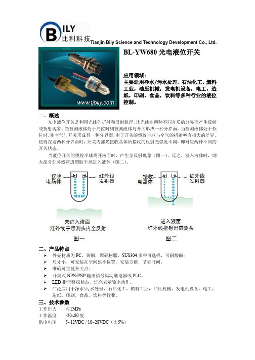
一、概述光电液位开关是利用光线的折射和反射原理,让光线在两种不同介质的分界面产生反射或折射现象。
当被测液体处于高位时则被测液体与开关形成一种分界面,当被测液体处于低位时,则空气与开关形成另一种分界面,由于开关的塑胶半球与空气的折射率有很大的差异,使得在这两种分界面时,开关内部光接收晶体所接收的反射光强度不同,即对应两种不同的开关状态。
当液位开关的塑胶半球离开液面时,产生全反射现象(图一),反之,浸入液体时,则大部分红外线穿透塑胶半球进入液体(图二)。
二、产品特点外壳材质为PC,黄铜,聚砜树脂,SUS304多种可选择,可耐酸碱;尺寸小,可安装在空间狭小位置,安装方便,节省时间;准确可重复开关点;开集式NPN/PNP输出信号驱动继电器或PLC。
LED指示警报状态,灯亮表示输出动作。
广泛应用于净水/污水处理,石油化工,燃料工业,油压机械,发电机设备,电工,造纸,印刷,食品,饮料等行业。
三、技术参数工作压力≤1MPa工作温度-20~80度供电电压5~12VDC / 10~28VDC(±5%)Tianjin Bily Science and Technology Development Co., Ltd.供电电流500mA 输出类型NPN ,PNP 以及开关量输出类型 可选材质PC ,黄铜, 聚砜树脂,SUS304 适用介质油、废水、水性溶液,酒类,酒精等。
导线长度20AWG ,250mmPTFE 线,8mm 镀锡 连接方式 G 管螺纹,NPT 锥管螺纹,M 制螺纹以及SAE (带O 型圈)多种连接方式。
四、选型型号说 明BL-YW680─ □ /□/□ /□ /□ 封装材质 PPC J聚砜树脂 C黄铜 SSUS304 输出形式 K开关输出 PPNP 输出 NNPN 输出 供电电压 015 VDC 025~12 VDC 0310~28VDC 连接方式 -G0M12X1 -G11/4 NPT -G21/2 NPT -G3G1/2 触点形式 NO 常开触点NC 常闭触点 五、仪表接线。
SOR液位开关使用说明书

基本原理上升的液面将浮球或弹簧提升式沉筒浮起,带动磁力短管上升至磁场区,吸引并触发电路或气路开关(发出液位到达信号)。
液面下降时,次序相反,电路或气路开关被释开(发出液位下降信号)。
磁力滑块(通过密封套筒)将永久磁铁和开关组件与过程液面隔离,避免磁铁腐蚀和磁力碎屑堆积。
磁力运动传输消除了由机械装置弯曲运动传输带来的疲劳,损坏及过早失效等问题。
磁力运动传输避免了因探杆型传感器引起的表面涂层问题。
在没有工厂允许的情况下,不要改变开关的原件和结构。
沉筒式结构液面下降时各次序相反,磁力短管下落至磁场外,复位弹簧将外部磁铁拽离密封套管,微动开关复位。
浮球式结构SOR液位开关使用说明书浮球与一根机械连杆固定在一起,液面上升至浮球,浮力使连杆上升,磁力短管升入密封套筒中,磁力短管的向上运动是在外部永久磁铁产生的磁场内。
磁力把外部磁铁吸向磁力短管,牢固地吸附在密封套管上,此时,微动开关被触发。
液面下降时各次序相反。
磁力短管下落至磁场外,复位弹簧将外部磁铁拽离密封套筒,微动开关复位。
沉筒悬挂在弹簧平衡联动杆上,液面上升时,沉筒的有效重量因受浮力而减小,弹簧回缩拉起连杆,使磁力短管在密封套筒中上升。
磁力短管的向上运动是在外部永久磁铁产生的磁场内,磁力把外部磁铁吸向磁力短管,牢固地吸附在密封套筒上,此时,微动开关被触发。
引压口联接外浮筒接管应当平直且不受干扰,控制头与外浮筒垂直中心线在3℃内。
注意:顶装式控制头与容器法兰或短管安装成与容器的垂直或水平中心线不超过3℃。
(即:外浮筒式与顶装式均应垂直安装)接管长度应控制在最小,以使开关整体更稳定。
如有需要,应采用接管悬挂或支承装置。
控制机构在液体中动作,接管中很可能堆积沉淀物,应采用“T”形或“+”形管接头,允许定期清洗接管。
排污阀及吹扫阀可用于清洁外浮筒和接管。
正常运行中,所有接管上阀门应完全打开,因为限流可能导致误动作。
警告:介质温度超过232℃时,不推荐在外浮筒上使用保温材料。
SOR液位开关使用说明书

SOR液位开关使用说明书SOR液位开关使用说明书工作原理上升的液面将浮球或弹簧提升式沉筒浮起,带动磁力短管上升至磁场区,吸引并触发电路或气路开关(发出液位到达信号)。
液面下降时,次序相反,电路或气路开关被释开(发出液位下降信号)。
磁力滑块(通过密封套筒)将永久磁铁和开关组件与过程液面隔离,避免磁铁腐蚀和磁力碎屑堆积。
磁力运动传输消除了由机械装置弯曲运动传输带来的疲劳,损坏及过早失效等问题。
磁力运动传输避免了因探杆型传感器引起的表面涂层问题。
在没有工厂允许的情况下,不要改变开关的原件和结构。
沉筒式结构SOR液位开关使用说明书沉筒悬挂在弹簧平衡联动杆上,液面上升时,沉筒的有效重量因受浮力而减小,弹簧回缩拉起连杆,使磁力短管在密封套筒中上升。
磁力短管的向上运动是在外部永久磁铁产生的磁场内,磁力把外部磁铁吸向磁力短管,牢固地吸附在密封套筒上,此时,微动开关被触发。
最新的信息可以登陆查询通过ISO9001认证液面下降时各次序相反,磁力短管下落至磁场外,复位弹簧将外部磁铁拽离密封套管,微动开关复位。
浮球式结构引压口联接外浮筒接管应当平直且不受干扰,控制头与外浮筒垂直中心线在3℃内。
注意:顶装式控制头与容器法兰或短管安装成与容器的垂直或水平中心线不超过3℃。
(即:外浮筒式与顶装式均应垂直安装)接管长度应控制在最小,以使开关整体更稳定。
如有需要,应采用接管悬挂或支承装置。
控制机构在液体中动作,接管中很可能堆积沉淀物,应采用“T”形或“+”形管接头,允许定期清洗接管。
排污阀及吹扫阀可用于清洁外浮筒和接管。
正常运行中,所有接管上阀门应完全打开,因为限流可能导致误动作。
警告:介质温度超过232℃时,不推荐在外浮筒上使用保温材料。
电气接线警告:在开启开关外壳之前,一定要保证电源已经被断开。
忘记断开电源可能会导致严重个人伤害或巨大的财产损毁。
请确认接线以及接线的联接符合所有当地和国际电气规范。
外壳上的电气接口可旋转360°,只需松开外壳底座的定位螺钉即可。
音叉液位开关说明书

目录
1 3 5 9 12
了解产品
标准型
Ф86 26
接线盒 M20×1.5(电 气 接 口)
113
六方
动作点标记 20
39
插入深度
叉体方向标记
12
R1(安 装 接 口)
100 28
叉体
5 动作点
约15
25
说明:接线盒为铝合金压铸表面喷塑,其余为304不锈钢 图1
安装方法
注意事项: ◇正确持拿
◇不能改变叉体形状
◇用户拆装液位开关时禁止用手抱住壳体拧动,应使用扳手拧动 六角螺栓。 安装方法 8
电气连接
仪表面板分布图:
延时设定 输出指示灯
电源指示灯
灵敏度调整 标定完成指示灯
标定按键 上/下 限 位 选 择 接线端子
电源 输出
1234
·接线端子 端子“1”、“2”接AC 220V或DC 24V电源(定货时 指定其中一种)。端子“3” 、“4”为继电器接点 输出。(仪表设置为“上限位”时为有料吸合,仪 表设置为“下限位”时为空料吸合)
电晶体激励产生振动,当音叉被液体或固体浸没时振动频率发生变 化,这个频率变化由电子线路检测出来并输出一个开关量,达到液 位报警或控制的目的。
音叉式液位开关的结构及原理特性使其能够取代任何一种机理 的液位开关,广泛应用于石化、冶金、轻工、建材等行业中对液位 进行上/下限位报警及控制。
技术 指标: ◇电 源电 压: AC 220V 5 0H z或DC 24V ◇工 作温 度: 叉体 -30~1 5 0℃
W: 高温 型:小 于150℃
Y: 高压型:小 于2MPa
特
殊
液位开关 - 安装、操作和兼容性指南说明书

LIQUID LEVEL SWITCHES – Installation, Operation and Compatibility GuideTo ensure the best performance from your equipment it is important that the attached liquid level switch is installed and maintained correctly.This document provides an overview of SST Sensing’s liquid level switches including mounting information, operating principle and fluid compatibility.Contents1 DEFINITIONS ........................................................................................................................... 1-12 TECHNICAL SPECIFICATIONS ................................................................................................... 2-13 INSTALLATION ........................................................................................................................ 3-1 3.1 General Guidelines .......................................................................................................... 3-13.2 Electrical Connections ..................................................................................................... 3-24 OPERATION ............................................................................................................................ 4-1 4.1 Operating Principle Overview .......................................................................................... 4-1 4.2 Fluid Compatibility Guide ................................................................................................ 4-24.3 Test Process .................................................................................................................... 4-45 MAINTENANCE ....................................................................................................................... 5-1 5.1 Cleaning .......................................................................................................................... 5-1 5.2 Disposal .......................................................................................................................... 5-11DEFINITIONSThe following definitions apply to WARNINGS, CAUTIONS and NOTES used throughout this manual.WARNING:The warning symbol is used to indicate instructions that, if they are not followed, can result in minor, serious or even fatal injuries to personnel.CAUTION:The caution symbol is used to indicate instructions that, if they are not followed, can result in damage to the equipment (hardware and/or software), or a system failure occurring.NOTE: Highlights an essential operating procedure, condition or statement.2TECHNICAL SPECIFICATIONSThe following table summarises the key technical specifications. Refer to the appropriate datasheet for more in-depth information (see REFERENCE DOCUMENTS).Switch VoltageRange TemperatureRangeOutputCurrentOutputTypeOutputLogicOptomax Digital 4.5 to 15.4V DC-25 to + 80o Cor-40 to +125o C Up to100mAPush Pull High in AirLow in AirPWMOptomax Industrial 4.5 to 15.4V DCor8 to 30 V DC -25 to + 80o Cor-40 to +125o CUp to1AN-TypeP-TypePush PullHigh in AirLow in AirOptomax Industrial Glass 4.5 to 15.4V DCor8 to 30V DC -40 to +125o C Up to1AN-TypeP-TypePush PullHigh in AirLow in AirLLHP 4.5 to 15.4V DCor10 to 45V DC -25 to + 80o Cor-40 to +125o CUp to800mAN-TypeP-TypePush PullHigh in AirLow in AirPOS 12 to 28V DC-25 to 100o Cor-40 to + 140o C Up to200mAN-TypeP-TypeHigh in AirLow in AirOptomax Basic a 3.3 to 24V DC -25 to + 80o C 4mA Phototransistor outputfor customer tointerface to theirsystemNOTE: If you need a switch other than those listed above, contact SST Sensing; we will be happy to discuss your requirements.a Designed primarily for price sensitive, high volume OEM applications; power supply and microcontroller not supplied with this switch.3INSTALLATIONTo ensure the best performance from your product, it must be installed correctly.3.1General GuidelinesOptical liquid level switches should be mounted from the side or from the bottom for best results.NOTE: Mounting from the top down is not normally advised as false readings can be caused by liquid droplets clinging to the sensing tip. However, if the liquid viscosity is low, then pointing downwards if often fine. Additionally, if the application is a high level alarm and its activation results in the machine shutdown for example, pointing downwards may be acceptable.If you wish to mount in this position, contact SST Sensing to discuss the implications.Avoid mounting positions where ambient light is likely to point directly at the sensing tip, as false readings can occur.Switch performance can be affected by reflective surfaces in front of the sensing tip. ContactSST Sensing if you wish to use a switch within 10mm of a reflective surface (see NOTE).NOTE:If you are installing an LLG switch, avoid reflective surfaces within 50mm of the sensing tip.Figure 3-1 - Example Mounting Positions3.2Electrical ConnectionsCAUTION:•Do NOT immerse the wires in fluid, over time, this will result in irreparable damage to the switch.•Take care when connecting loads. The minimum load impedance should not exceed Vs/max output current. Check the relevant datasheet BEFORE installation.•Shorting the output to Vs or 0V will result in irreparable damage to the switch.•Do NOT install the switch suspended from the cable.•Avoid exerting excessive tensile force on the cable (e.g. tugging).The liquid level switch termination configuration varies depending on the range and selection ordered (refer to the specific datasheet for more detail); in general, connect as follows:Optomax Digital, Industrial and Glass Tip Ranges∙Vs Red∙Output b Green∙0V BlueLLHP Range c∙Vs Red∙Output b Green or white∙0V Blue or blackPOS Range c∙Vs Brown∙Output b Black∙0V BlueOptomax Basic Range∙3-wire versiono LED Anode Redo Output b Greeno0V Blue ∙4-wire versiono LED Anode Redo Output b Greeno0V LED Blueo0V Phototransistor Blackb Refer to the datasheet for output logic details.c Brad Harrison connector available as an alternative to the cable / flying lead options.4OPERATIONOptical liquid level switches do not measure the liquid level, instead they detect the presence or absence of liquid. For an overview of the switches refer to AN-0061, Liquid Level Switches – Selection Guide, more detailed spec information is contained in the switch datasheets; refer to REFERENCE DOCUMENTS for details.4.1Operating Principle OverviewOptical liquid level switches use an infra-red LED and phototransistor accurately positioned at the base of the sensor tip.When the tip is in air, infra-red light reflects internally round the tip to the phototransistor providing strong optical coupling between the two. When the sensor tip is immersed in liquid, the infra-red light escapes from the tip causing a reduction in the amount of light at the phototransistor which makes the output change state.Sensor Tip in Air Sensor Tip Immersed in Liquid4.2Fluid Compatibility GuideThe environment in which the liquid level switch is operating influences the life of the product. To ensure the switch does not fail prematurely, the following material/fluid compatibility should be noted:4.2.1PolysulfoneWhilst the following list may be used as a guide and gives common industrial fluids that are typically acceptable, we recommend that before use you check that the fluid you wish to use this device in is compatible with Polysulfone. Refer to 4.3 Test Process on page 4-4.Acetic acid – GlacialAcetic acid – 10% Ammonia – 88 Ammonium Hydroxide – 10% Ammonium Chloride – 10% Aviation spiritBenzeneBenzoic acidBleachBrineButaneCalcium NitrateCalcium Hypochlorite Carbon Tetrachloride Chromic acidCopper Sulphate CreosoteCyclohexane CyclohexanolDetergent solutionsDiesel fuelDiethylamineDiethyl EtherDioctyl PhthalateEdible fats & oilsEthanol – 50%Ethyl AlcoholEthylene GlycolFerric Chloride FormaldehydeFormic acid GlycerolHeptaneHydrochloric acid – 10% Hydrochloric acid conc. Hydrogen Peroxide IsopropanolIso-OctaneKeroseneLinseed oilMagnesium Sulphate MethanolMotor oilNitric acid 10%Oils - VegetableOxalic acidPetroleum Ether Potassium Hydroxide – 10% Potassium Hydroxide – 50% Silicone fluidsSilver NitrateSoap solutionSodium ChlorideSodium Hydroxide – 10% Sodium Hydroxide – 50% Sulphuric acid – 10% Transformer oil TurpentineVarnishWaterWhite Spirit4.2.2Trogamid®Whilst the following list may be used as a guide and gives common industrial fluids that are typically acceptable, we recommend that before use you check that the fluid you wish to use this device in is compatible with Trogamid® (EU food-contact grade). Refer to 4.3 Test Process on page 4-4.AcetoneBenzeneBreak Free (lubricating oil) Carbon tetrachloride Econa PG32 (Hydraulic fluid) EthanolEthyl acetateEucalyptus oil Formaldehyde solution Glycerine (DAB6)Heating oilIsopropanol MethanolMountain pine oilPetroleum etherPotassium hydroxide (25 w/w-%) Potassium hydroxide (50 w/w-%) Premium gasoline1,2-propane diolRegular gasTest fuel (M15)TolueneXylene4.2.3GlassGlass tipped switches are extremely robust to most chemicals however, chemicals which will attack glass, for example Hydrofluoric acid, are to be avoided. We recommend that before use you check that the fluid you wish to use this device in is compatible with glass. Refer to 4.3 Test Process on page 4-4.4.3Test ProcessThe chemical compatibility lists are not exhaustive and customers often want to use the switches with liquids that have not been approved before. In this case, a compatibility test should be performed using a sensor made with the material (Polysulfone, Trogamid®, glass or stainless steel) you wish to use.The test is simple and is performed as follows:1.Submerge the sensor tip and threads in the liquid of interest. Do NOT submerge the wires.2.Heat the liquid to the maximum expected operating temperature.CAUTION: Assuming it is safe to do so.3.Leave the switch in this liquid at the maximum operating temperature for two weeks.4.Remove the switch and inspect it for signs of:∙Cracking∙Crumbling∙Crazing∙Melting∙Deformation∙SwellingAssuming the switch appears to be unaffected, it should be tested in accordance with its operating procedure to ensure it remains functional.If the switch passes its functional tests, then the liquid can be considered to be compatible with the switch housing material.5MAINTENANCE5.1CleaningIf cleaning of the tip is necessary (i.e., if there is a buildup of algae or other reside), clean the outer surfaces using alcohol based cleaning agents.CAUTION: If your switch is Polysulfone or Trogamid®, do NOT use chlorinated solvents such as tricholoroethane as these are likely to attack the switch material.5.2DisposalLiquid level switches contain electrical components, for this reason they must be disposed of as electrical waste. Please observe your local regulations.Page | 5-1AN-0041 Rev 8 © 2017 SST SENSING LTD.REFERENCE DOCUMENTSRefer also to the following documents for additional information:CAUTIONDo not exceed maximum ratings and ensure sensor(s) are operated in accordance with their requirements.Carefully follow all wiring instructions. Incorrect wiring can cause permanent damage to the device. SST Sensing Ltd recommend using alcohol based cleaning agents. If your switch is Polysulfone or Trogamid®, do NOT use chlorinated solvents such as trichloroethane as these are likely to attack the switch material.Failure to comply with these instructions may result in product damage.INFORMATIONAs customer applications are outside of SST Sensing Ltd.’s control, the information provided is given without legal responsibility. Customers should test under their own conditions to ensure that theequipment is suitable for their intended application. Before use, check that the fluid in which you wish to use these devices is compatible either with Polysulfone, Trogamid®, glass or stainless steel. For technical assistance or advice, please email: ************************SST SENSING LIMITED, 5 HAGMILL CRESCENT, SHAWHEAD INDUSTRIAL ESTATE, COATBRIDGE, UK, ML5 4NS | e: ******************** | t: +44 (0)1236 459 020 | f: +44 (0)1236 459 026。