第七章 PIC TO EMC
SIMOCODE pro PCS 7 库函数开始指南说明书
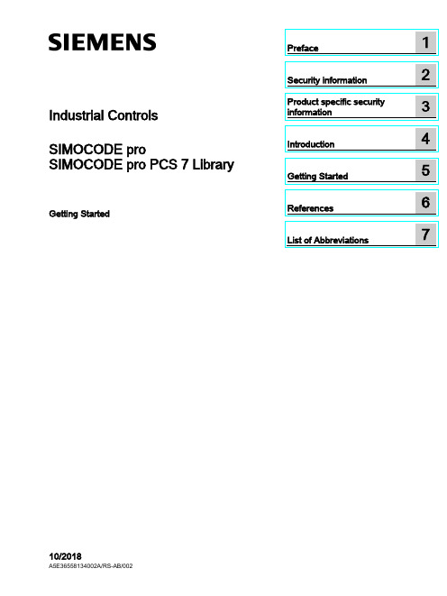
Industrial Controls SIMOCODE pro SIMOCODE pro PCS 7 LibraryGetting Started10/2018Siemens AGDivision Digital Factory Postfach 48 483ZX1012-0CS16-5BC1Ⓟ10/2018 Subject to change Copyright © Siemens AG 2016. All rights reservedLegal informationWarning notice systemThis manual contains notices you have to observe in order to ensure your personal safety, as well as to prevent damage to property. The notices referring to your personal safety are highlighted in the manual by a safety alert symbol, notices referring only to property damage have no safety alert symbol. These notices shown below aregraded according to the degree of danger.indicates that death or severe personal injury will result if proper precautions are not taken.WARNINGindicates that death or severe personal injury may result if proper precautions are not taken.CAUTIONindicates that minor personal injury can result if proper precautions are not taken. NOTICEindicates that property damage can result if proper precautions are not taken.If more than one degree of danger is present, the warning notice representing the highest degree of danger will be used. A notice warning of injury to persons with a safety alert symbol may also include a warning relating to property damage.Qualified PersonnelThe product/system described in this documentation may be operated only by personnel qualified for the specific task in accordance with the relevant documentation, in particular its warning notices and safety instructions. Qualified personnel are those who, based on their training and experience, are capable of identifying risks and avoiding potential hazards when working with these products/systems.Proper use of Siemens productsNote the following:WARNINGSiemens products may only be used for the applications described in the catalog and in the relevant technical documentation. If products and components from other manufacturers are used, these must be recommended or approved by Siemens. Proper transport, storage, installation, assembly, commissioning, operation andmaintenance are required to ensure that the products operate safely and without any problems. The permissible ambient conditions must be complied with. The information in the relevant documentation must be observed.TrademarksAll names identified by ® are registered trademarks of Siemens AG. The remaining trademarks in this publication may be trademarks whose use by third parties for their own purposes could violate the rights of the owner.Disclaimer of LiabilityWe have reviewed the contents of this publication to ensure consistency with the hardware and software described. Since variance cannot be precluded entirely, we cannot guarantee full consistency. However, the information in this publication is reviewed regularly and any necessary corrections are included in subsequent editions.Table of contents1 Preface (5)2 Security information (7)3 Product specific security information (9)4 Introduction (11)4.1 Introduction (11)5 Getting Started (13)5.1 Installation (13)5.2 HW Config (14)5.3 CFC (17)5.4 Operator Station (23)6 References (35)7 List of Abbreviations (37)7.1 Abbreviations (37)SIMOCODE pro PCS 7 LibraryTable of contentsSIMOCODE pro PCS 7 LibraryPreface 1 Brief descriptionThe Getting Started of the SIMOCODE pro PCS 7 Library uses a simple example project toshow you the basic procedures:●Basic configuration steps●Handling and monitoring different signal blocks●ParameterizationThis Getting Started manual is intended to be an introduction and largely dispenses withdetailed information and background information.RequirementsBasic knowledge of creating a PCS 7 project is necessary. You will find information aboutConventionsThis documentation contains designations of the software interface elements. If you haveinstalled a multi-language package for the operating system, some of the designations willbe displayed in the base language of the operating system after a language switch and will,therefore, differ from the designations used in this documentation.Versions and documentationSIMOCODE pro PCS 7 LibraryPrefaceSIMOCODE pro PCS 7 LibrarySoftware required for the Getting Started of the SIMOCODE pro PCS 7 Library● You can execute the example project on any PC or programming device on which the following software is installed: – Windows operating system – Internet Explorer– Message Queuing service – SQL serverNoteThe versions required depend on the version of PCS 7 installed.You can find further relevant details in the following manuals:–on the – ● To do so, follow the instructions in the Process Control System PCS 7; Getting StartedHardware required for creating an example projectThis PCS 7 example project was created with the following hardware for the automation station (AS):Table 1- 1Hardware - Automation station 1: Configuration direct on the master systemOrder numberDescription6ES7 410-5HX08-0AB0 SIMATIC S7-400, CPU 410-5H with 1*DP and 2*PN interfaces6ES7 407-0KA02-0AA0SIMATIC S7-400, power supply PS 407 10A, AC 120/230V/10A standard PSTable 1- 2SIMOCODE HardwareOrder number Description3UF7 010-1A*00-0SIMOCODE pro V Basic UnitSecurity information 2 Siemens provides products and solutions with industrial security functions that support thesecure operation of plants, systems, machines and networks.In order to protect plants, systems, machines and networks against cyber threats, it isnecessary to implement – and continuously maintain – a holistic, state-of-the-art industrialsecurity concept. Siemens’ products and solutions constitute one element of such a concept.Customers are responsible for preventing unauthorized access to their plants, systems,machines and networks. Such systems, machines and components should only beconnected to an enterprise network or the internet if and to the extent such a connection isnecessary and only when appropriate security measures (e.g. firewalls and/or networksegmentation) are in place.For additional information on industrial security measures that may be implemented, pleasevisithttps:///industrialsecurity.Siemens’ products and solutions undergo continuous development to make them moresecure. Siemens strongly recommends that product updates are applied as soon as they areavailable and that the latest product versions are used. Use of product versions that are nolonger supported, and failure to apply the latest updates may increase customer’s exposureto cyber threats.To stay informed about product updates, subscribe to the Siemens Industrial Security RSSFeed underhttps:///industrialsecurity.SIMOCODE pro PCS 7 LibrarySecurity informationSIMOCODE pro PCS 7 LibraryProduct specific security information 3 Product specific security informationThis library is designed to run under the PCS 7 environment. Therefore, it is recommendedto follow the security principles for PCS 7 to support a secure operation, such as:●User rights●Password protection of–WinCCSIMOCODE pro PCS 7 LibraryProduct specific security informationSIMOCODE pro PCS 7 LibraryIntroduction 4 4.1IntroductionIntroductionThis document explains the basic principles of using the SIMOCODE pro PCS 7 Library. TheSIMOCODE pro PCS 7 Library is designed according to APL standards for both, blocks andfaceplates. This library contains CFC templates to fulfill the control functions of a MotorManagement device.For reducing configuration time on site, a module driver generator is included with thislibrary. By using this driver generator it is ensured that all necessary interconnections will behandled automatically by the system and the device is ready to operate in PCS 7environment.Custom configuration can be done by the user as well. User manual and online help will givedetailed information about the blocks and their input and output pins.This document will guide you through the necessary steps for using the template and themodule driver generator in a PCS 7 environment using a sample project. This sample usesminimum hardware, single station, one PLC connected to one SIMOCODE pro V viaPROFIBUS.PrerequisitesUserPCS 7 knowledge:●Project creation●HW-Config●CFC-Editor●WinCC-Explorer●WinCCYou can find the manuals for your PCS 7 Version in the manual collection.Introduction4.1 IntroductionSystem●Installed and compatible PCS 7 version●Installed SIMOCODE pro PCS 7 Library●PCS 7 Multiproject (created by Project-Wizard).Refer read me for this library for software details and steps to follow to change the existingproject to migration.CommunicationActive communication network between Engineering Station (ES)/Operator Station (OS) andthe PLC.Getting Started 5 5.1InstallationInstallationThe Setup program will guide you through the required steps. Use "< Back" and "Next >"buttons to navigate through the screens during the installation process. The installationprogram supports German and English. Please choose your language at the initial screen.The SIMOCODE pro library has two components:●AS = Components for Automation System●OS = Components for Operator StationFor example, this library has:●Library for SIMOCODE pro PCS 7 AS●Faceplates for SIMOCODE pro PCS 7 OSInstallation program will ask you to decide, which product you want to install. Below is thedecision matrix:AS OSSingle Station X XAS OSDistributed System Engineering Station X -Operator Station - X'X' - required, '-' - not required5.2 HW Config5.2HW ConfigHW ConfigOpen HW-Config and switch the hardware catalog profile to Standard.Below are the SIMOCODE pro objects for:Communication Integration Catalog pathPROFIBUS OM at PROFIBUS DP > Switching Devices >Motor Management SystemEDD PROFIBUS DP > Switching DevicesGSD PROFIBUS DP > Additional Field De-vices > Switching Devices >SIMOCODEPROFINET OM PROFINET IO > Switching devices >Motor Management SystemEDD1.2PROFINET IO > Switching devices >Motor Management System > GSD3GSDML1.21SIMOCODE pro V GSD (V1.5) and GSDML: Insert the Basic Type which meets yourrequirement.2The same object is used for GSD and EDD integration in HW-Config. Configuration viaPDM for EDD support needs to be activated by the user in Object Properties (Alt+Return) ofthe SIMOCODE pro Object.3Folder entry GSD will be created in case of parallel integration of SIMOCODE pro OM,integrated via SIMOCODE ES.Drag and drop the desired SIMOCODE pro-Object into the Station Window and connect itwith PROFIBUS resp. PROFINET line.5.2 HW ConfigBasic TypesThe length of the I/O data of the SIMOCODE pro device varies by the configured BasicType. The Basic Type defines how many valid data will be sent and received by the device inevery cycle. Bytes 2 and 3 are predefined and used for the max. Current I max. More bytes,supported by basic types 1 and 3, may be fed with user defined data. Following tablesdisplay the existing Basic Types along with the supported data length:Cyclic send data (SIMOCODE pro > PLC)Cyclic receive data (PLC > SIMOCODE pro)The following table shows which Basic Type is supported by the different SIMOCODE proBasic Units:Basic Unit Basic Type 1 Basic Type 2 Basic Type 3SIMOCODE pro C - X -SIMOCODE pro S X X -SIMOCODE pro V X X -SIMOCODE pro V PN X X X'X' - supported, '-' - not supportedSelect the Basic Type which meets your requirements in HW-Config catalog. Please finddetailed information about the Basic Type in the system manuals for SIMOCODE prodevices.5.2 HW ConfigInput AddressRetrieve the input address of the SIMOCODE pro device:NoteNote down the input address or insert it in symbol table of HW-Config (Options > SymbolTable or Ctrl+Alt+T) for later usage.Each address in the symbol table should have a valid symbolic name.5.3 CFC 5.3CFCMaster data libraryFor using the library in a plant, it is recommended to store the templates of the SIMOCODEpro PCS 7 Library in the Master data library. Since this is beyond the scope of thisdocument, we recommend you to take a look at:With the templates stored in the Master data library, follow the below steps.CFC Template1.Open CFC-Editor by double clicking on the desired CFC-Object.2.Select the tab Libraries, located underneath the Catalog view. If the templates ofSIMOCODE pro PCS 7 Library were placed in the Master data library, you will find themin the project library folder (Notation: "Project Name"+"_Lib" e.g.:GS_SIMOCODEpro_Lib). Otherwise you will find the templates in the SIMOCODE proLibrary (e.g.: SMCPro_PCS7_LibV90SP1).5.3 CFC3.Expand the Master data library node ("ProjName" + "_Lib" e.g.: GS_SIMOCODEpro_Lib).You will find two nodes:–Blocks–Charts5.3 CFC4.Expand the Charts node. Now you will see the SIMOCODE pro PCS 7 Library templates.SIMOCODE pro Library supports following control functions:Control Function TemplateDahlander Starter DahlandDirect Starter DirectMolded Case Circuit Breaker MCCBOverload Relay OvlRlyPole-Changing Starter PoleChngPositioner 1~5 PositnerDahlander Reversing Starter RevDahlReversing Starter ReversePole-Changing Reversing Starter RevPolChSoft Starter with Reversing Contactor RevSoftStrStar-Delta Reversing Starter RevStarDelSoft Starter SoftStrSolenoid Valve SolValveStar-Delta Starter StarDel5.Drag the desired template object (e.g.: Direct) by pressing left mouse button and drop theobject in the Chart view.Direct template is now instantiated.5.3 CFCOpen the Template1.Right click on the instantiated Direct template in the chart view and select Open. Thetemplate opens in a new chart view.Set I/OInput1.Scroll to the left, till you see the sheet bar. There you will find a textual interconnectionnamed Input Word Address of Simocode base Module.Now you have two options:–Setting the HW input address manually, as seen in HW-Config–Use symbol table for selecting the input address.Since this is a short example, we will just hand over the devices input address as it isdisplayed in HW-Config. We recommend using the symbol table for large projects. Refer2.Right click on Input Word Address of Simocode base Module and select Interconnectionto Address.A symbol table like dialog opens.5.3 CFC 3.Insert input address, in this case: IW512.4.Confirm input value by pressing enter. Now the blocks input address is connected to thedevices input address.MMMeas, MMStat and MMLogIf you want to use measurement, statistic values and/or logbook (MMMeas, MMStat and MMLog) for the SIMOCODE pro device, you need to switch to sheet view 2 in the CFC plan. There you will find the additional blocks for the mentioned functions.Repeat the Interconnection to Address, steps from above for this sheet.NoteIf you do not want to use the additional functions, you are free to delete the function blocks in question or all blocks in sheet 2.Result: The basic block set up is now complete.5.3 CFCGenerate module drivers1.Go to Chart > Compile > Chart as Program or hit Ctrl+B or click in the toolbar. TheCompile dialog opens.2.Ensure that the option Generate module drivers is checked in.3.Confirm dialog with the OK-Button.After compilation has finished, the Logs dialog will be displayed.1.Confirm this dialog by Close button.2.Now hit F5 in the chart view. The view will be updated and all textual interconnections arereplaced by the according block interconnection.DownloadThe CFC-Template is now ready for download.Go to CPU > Download or hit CTRL+L or use in the toolbar.Result: Template set up is now complete and ready to use.5.4 Operator Station 5.4Operator StationOperator StationBlock icons and faceplates are inserted in the project while compiling the Operator Station(OS). Compile OS. You can find details on how to work with the Operator Station in theBlock IconsAfter activating WinCC you will find the APL block icon for the motor block:Activate Block iconsThis library is also shipped with block icon for MMOprtn. It is disabled by default setting. Ifyou need MMOprtn block icon you can simply activate it:1.Open CFC-Editor.2.Select the MMOprtn block.3.Right click and select Object Properties in the context menu.4.Check in the checkbox for Create block icon.5.4 Operator Station5.Confirm the Properties dialog by clicking OK.pile the OS and activate WinCC. Now you will find two block icons: MotL andMMOprtn.5.4 Operator Station The block icons in detail are:MotLMotor - Large MMOprtnSimocode pro Direct starter OperationThe block icons give a general feedback of the current device status to the user. Pleaseopen a faceplate for detailed information about the device by clicking on the block icon.FaceplatesStandard faceplates of the block icons:NoteFor further information on how to use the Library, refer the latest "Programming andOperating Manual for the "SIMOCODE pro PCS 7 Library" Block Library.APL - MotL5.4 Operator StationMMOprtnMMMeas5.4 Operator Station MMStatMMLog5.4 Operator StationFaceplate-ViewsEach faceplate provides multiple views:APLSIMOCODE pro LibraryMotL MMOprtn MMMeas MMStat MMLog • Standard • Messages • Trends • Parameters • Preview • Memo • Batch• Standard • Messages • Limits • Trends • Preview• Status diagnostics • Event diagnostics • Warning diagnos-tics • Trip diagnostics • Station diagnostics • Process image • Batch• Current • Voltage • Analog • Temperature • Messages • Trends • Preview • Batch• Standard 1 • Standard 2 • Messages • Preview • Batch• Standard • Messages • Logbook • Preview • BatchYou can switch between the single views by clicking the demanded view button.Click onto open additional view buttons.Faceplates may be pinned or closed according to the demands of the user. Furtherinformation on how to use the faceplates can be found in the online help, shipped with this library or in the user manual provided for this library.5.4 Operator StationNavigation between faceplates1.Open the Standard view of block MotL.2.Click on button Operation.MMOprtn faceplate opens.Click on navigation button to return to the calling faceplate.5.4 Operator Station3.Click on button Measurement to open the MMMeas faceplate.5.4 Operator StationMMStat1.Open the Standard view of block MotL.2.Click on button Operation.MMOprtn faceplate opens.Click on navigation button to return to the calling faceplate.5.4 Operator Station3.Click on button Statistic to open the MMStat faceplate.5.4 Operator StationMMLog1.Open faceplate MMOprtn and switch to view Preview.2.Click on button Operation.MMOprtn faceplate opens.Click on navigation button to return to the calling faceplate.5.4 Operator Station3.Click on button Logbook to open the MMLog faceplate.NoteClick on navigation button at the MMMeas, MMStat or MMLog faceplate to return to thecorresponding MMOprtn faceplate.References6More informationAdditional information can be found as follows:●● ● ● ● ●ReferencesList of Abbreviations 7 7.1AbbreviationsOverviewTable 7- 1 Meaning of abbreviationsAbbrevia-MeaningtionAS Automation stationCFC Continuous Function ChartEDD Electronic device descriptionGSD Generic Station DescriptionHMI Human machine interfaceHW Config "Hardware configuration" module in the SIMATIC ManagerOM Object managerOS Operator stationPCS 7 Process Control System 7CPU Central Processing UnitSS Soft starterList of Abbreviations 7.1 Abbreviations。
电机控制开发套件motorBench 2.25说明书
Dashboard/…/motorBench 2.25 ReleasemotorBench 2.25.0 Release NotesCreated by Fernando Garibaldi, last modified by Jason Sachs 2 minutes agoOverview of motorBench® Development SuiteWhat’s NewSystem RequirementsSupported HardwareHigh-voltage hardwareOther hardware required with both low-voltage and high-voltage setupsInstalling motorBench® Development Suite 2.25.0RepairsMotor Control Fixed IssuesChanges since revision 2.15Known IssuesMotor Control IssuesLimitationsSupported DevicesSoftware LimitationsMotor Control LimitationsSupported Motor ParametersCustomer SupportThe Microchip Web SiteAdditional SupportOverview of motorBench® Development SuiteMicrochip motorBench Development Suite is a graphical, interactive development environment designed to help motor control engineers to design and implement motor control systems, from very basic to very sophisticated ones.motorBench® Development Suite allows the user to:configure a motor systemmeasure motor parameterstune the controller gainsgenerate code to spin the motorWhat’s New1. Motor Control Application Framework (MCAF) R5 – see MCAF User's Guide for more information.a. Added support for dsPIC33CK256MP508b. Added Angle-tracking PLL (ATPLL) supportc. Improved Customize page support in motorBench2. Customizea. Allow advanced customization of MCAF code generation3. Measurea. Updated fault handing logic to detect if an invalid load is connected to the inverter before starting motor parameter measurement or Board calibrationb. Improvements to support motors with large values of stator inductancec. Improvements to support motors with large inertia and high cogging torque4. MCC Integrationa. Improved support for MCC-generated peripheral and system initialization code5. Device Supporta. Added support for dsPIC33CK256MP508i. This device is not yet supported by the motor parameter measurement featureSystem RequirementsMPLAB X 5.30 or later.XC16 compiler version:Firmware generated by motorBench® Development Suite has been tested with XC16 1.41.33EP devices: XC16 1.36 or later are expected to work with motorBench®Development Suite but have not been extensively tested.33CK devices: Either of the following is required:XC16 1.50 or laterXC16 1.41 with DFP 1.2.66 or laterMPLAB Code Configurator®(MCC) Plugin Version 3.95.0 or laterPIC24/dsPIC33/PIC32MM library 1.166.0 or laterSupported HardwareThis release of motorBench®Development Suite supports both low-voltage and high-voltage setups.Low-voltage hardware1. dsPICDEM MCLV-2 Development Board [Part Number: DM330021-2]2. dsPIC33EP256MC506 External Op Amp Motor Control PIM [Part Number: MA330031-2] with silicon revision A8 or dsPIC33CK256MP508 External Op Amp Motor Control Pim[Part Number: MA330041-1].3. A three phase PMSM or BLDC motor that is compatible with 24V, such as the Hurst 24V BLDC motor DMA0204024B101 [Part Number: AC300022].4. 24V power supply [Part Number: AC002013] - ensure this connects to AC mains using a 2-prong cable. If you have an AC002013 with a 3-prong cable, please contact Microchip.High-voltage hardware1. dsPICDEM MCHV-2 Development Board [Part Number: DM330023-2] or dsPICDEM MCHV-3 Development Board [Part Number: DM330023-3]AC mains voltages 120VAC 60Hz and 220VAC 50Hz have been tested.2. dsPIC33EP256MC506 External Op Amp Motor Control PIM [Part Number: MA330031-2] with silicon revision A8 or dsPIC33CK256MP508 External Op Amp Motor Control Pim[Part Number: MA330041-1].3. A three phase PMSM or BLDC motor that is compatible with rectified AC mains voltage, such as the Leadshine 400W BLDC motor EL5-M0400-1-24 [Part Number: AC300025].Other hardware required with both low-voltage and high-voltage setups1. A USB-to-logic-level-UART converter from the following list:a. Saelig USB-COM-U or USB-COM-U13b. TRENDnet TU-S9 v2.02. Programming tool - one of the following tools: Real ICE, ICD33. Board calibration load resistors - this is optional, please see motorBench® Development Suite User's Guide document for more detailsInstalling motorBench ® Development Suite 2.25.0To install the MPLAB ® Code Configurator v3.95 Plugin1. In the MPLAB® X IDE, select Plugins from the Tools menu2. Select the Available Plugins tab3. Check the box for the MPLAB® Code Configurator v3, and click on InstallTo install different peripheral library version or motorBench ® Development Suite version when connected to internet1. Create a project with dsPIC33EP256MC506 or dsPIC33CK256MP508, or use the sample project.2. Open MPLAB® Code Configurator3. In the Versions tab under PIC24/dsPIC33/PIC32MM MCUs, find the multiple library versions (loaded version is indicated by the green check mark)4. Right-click on the required version of the library and select Mark for Load5. In the Versions tab under motorBench ® Development Suite find the multiple library versions (loaded version is indicated by the green check mark)6. Right-click on the 2.25.0 version of the library and select Mark for Load7. Click on Load Selected Libraries button to load the marked libraries.To install different peripheral library version or motorBench® Development Suite version when not connected to internet1. In the MPLAB® X IDE, select Options from the Tools menu2. Select Plugins tab3. Click on Install Library4. Add pic24-dspic33-pic32mm_v1.166.mc3lib5. Add motorBench_2.25.0.mc3lib6. Restart MPLAB® X IDERepairsMotor Control Fixed IssuesChanges since revision 2.15The following aspects of motorBench® Development Suite and the Motor Control Application Framework (MCAF) have been updated:MCAF has been updated to R5, includingChanges in R2:Support for DC link compensationSupport for overmodulationSupport for wider range of low-voltage motorsUpdated HAL for future MCHV2 supportUpdated Motor Control LibraryNumerous minor fixesChanges in R3:MCC system module compatibilityMCHV-2 and MCHV-3 supportInverter maximum current now has a 1:1 ratio with the maximum commanded dq-frame current of the drive, operating in FOC (in R2 this incorporated a deratingfactor)Other minor fixesChanges in R4:MCC peripheral supportParameter customizationQuadrature encoder supportAdded new startup method (Weathervane startup)Other minor fixesChanges in R5:Added device support for dsPIC33CK256MP508Added Angle-tracking PLL (ATPLL) sensorless estimatorImproved motorBench Customize page supportOther minor fixesSections in this release notes affected:Other RequirementsLimitationsSupported Motor ParametersKnown IssuesPlease note:We do not recommend using the MCP2200 USB to RS232 Demo Board [Part number: MCP2200EV-VCP ] with this release of motorBench® Development Suite.While testing, we have observed more frequent occurrence of a serial communication timeout issue while running motor parameter measurement using this cable.See Known Issues section of this document for more information (MCGUI-1141)Motor parameter measurement is only supported on dsPIC33EP256MC506 device.Issue Key Summary WorkaroundMBPLAN-673Serial port does not get closed programmatically when MCC exits during motor parametermeasurementIf you exit SC during execution, restart MPLAB X.MBPLAN-932Exception during attempted creation of a runtime properties class No workaround needed, this issue doesn't have an impact on thefunctionality.MBPLAN-984Improve error reporting for SC build errors in the event of a code generation failureMBPLAN-1095Switching projects after loading motorBench erroneously allows motorBench code to generate for new projectMBPLAN-1160"Import Motor" and "Export Motor" buttons can be clicked multiple times, opening multiple dialog boxesMotor Control IssuesIssue Key SummaryDB_MC-411Current calibration happens only once (at part reset) rather than upon entry to MCSM_RESET stateDB_MC-560Speed controller exhibits chattering behavior at voltage saturation hysteresis boundary (MCAF)DB_MC-978"Soft start" gate drive in board_service.c has duty cycle that is too smallDB_MC-1092PLL estimator may not converge into rotor reference frame while using the Classic startup method in MCAFDB_MC-1396PLL calculations in code generation do not allow motor.velocity.nominal to be more than 1250Hz electrical (=20kHz/8/2)DB_MC-1415With some motors and 12V operation, increased velocity margin improves startup but creates unstable estimatorDB_MC-1430Quanum MT4012 unstable in closed-loop operation at 4200 RPM speed and aboveDB_MC-1491With Quanum MT4012, MCAF may not detect stallDB_MC-1492Quanum MT4012 Stalls on pressing 'S3'(reverse) at low speeds and on changes to speed command potentiometerDB_MC-1495Anaheim BLY342D-24V-3000, BLY342D-48V-3200 motors creates hardware over-current during stall-detect testingDB_MC-1521Closed loop speed step response overshoot - MCHV2, Leadshine 400DB_MC-1892Some motors with extreme parameters may produce out-of-range error for stall_detect.group.timerCountsVarianceDetect (detected in Monte Carlo analysis)DB_MC-1920Board service isrCount-based timing is not guaranteedDB_MC-1922LED patterns not displayed when in the TEST_DISABLE or TEST_ENABLE statesDB_MC-2122BLWS232D motor startup in QEI mode causes a false detect for stall-detectionDB_MC-2213Deadtime needs to be changed in both MCC and motorBench to affect codeDB_MC-2275Large current rampup times may not start (STARTUP_TORQUE_RAMPUP_RATE = 0)DB_MC-2309QEI tracking loop Kp and Ki produce out-of-range errors for low-speed motorsDB_MC-2323Weathervane transition state should not have active damping enabledDB_MC-2387DC link voltage measurement may have too much phase delay for MCAF DC link compensation to work effectivelyDB_MC-2606MCC-generated code has incorrect IESO/FNOSC config bits for 33CKDB_MC-2671MCAF_CaptureTimestamp calls incorrect timer function for 33CK devicesDB_MC-2785Current sense signal integrity issue with 33CK during overmodulationLimitationsSupported DevicesmotorBench® Development Suite supports these devices:1. dsPIC33EP256MC5062. dsPIC33CK256MP508Software LimitationsmotorBench® Development Suite is tested for serial communication using Windows 7 and Windows 10 platforms. Other platforms may work with standard baud rates, but this operation has not yet been verified.Motor Control LimitationsFollowing are the known limitations for this release of motorBench® Development Suite:1. One mechanical load - constant load. This represents a mechanical load with constant inertia, viscous damping, and friction. The velocity control loop can generally rejectexternal disturbance torques, within the rated current of the motor and board, and within the bandwidth of the velocity control loop. Mechanical loads with time-varying or angle-varying inertia, viscous damping, and friction, such as a blower, compressor, or pump, are currently not supported.2. One motor type - PMSMMCLV-2:The reference motor is the Nidec Hurst motor DMA0204024B101 (MicrochipDirect part number AC300022). Microchip has also validated motorBench® DevelopmentSuite (including motor parameter measurement) with motors with parameters plotted below. Please also read the following section on Supported Motor Parameters. IfmotorBench® Development Suite is unable to spin a motor successfully, please contact Microchip staff for additional assistance.(Note: Mechanical time constant (2/3)×JR/Ke² represents the time constant of velocity acceleration under an open-loop synchronous-frame voltage step, neglecting the effects of inductance, with J, R, and Ke expressed in canonical metric units. R is expressed as line-neutral resistance = half of line-line resistance, and Ke is expressed as V/(rad/s) line-neutral zero-peak = Vrms/KRPM (line-line) × 0.007796968)MCHV-2/MCHV-3:The reference motor is the Leadshine 400W motor EL5-M0400-1-24 (MicrochipDirect part number: AC300025). Microchip has validated motorBench® DevelopmentSuite (including motor parameter measurement) with motors with parameters plotted below. Please also read the following section on Supported MotorParameters. If motorBench® Development Suite is unable to spin a motor successfully, please contact Microchip staff for additional assistance.3. Boarda. dsPICDEM™ MCLV-2 development board. This release of motorBench® Development Suite is compatible with modifications to the board to alter its rated current orvoltage. Contact your local Microchip office to obtain the document "Using MCLV-2 with motorBench® Development Suite to support alternative current and/or voltageratings", which provides guidance for such modifications. Other modifications may not be compatible.b. dsPICDEM™ MCHV-2 and MCHV-3 development boards. This release of motorBench® Development Suite is compatible with unmodified MCHV-2 and MCHV-3development boards.4. Motors should be well-matched to the board and operating voltage. The nominal DC link voltage of the MCLV-2 board is 24V. This voltage can be changed by cutting jumperJ6 and using an appropriate power supply connected to the appropriate terminals of J7. Use of a mismatched motor (for example, a 12V motor used with a 24V DC link voltage) may cause a hardware over-current fault; in this case motor parameter measurement may fail with the message "Fault Code #10: Undefined Fault". Retry with an appropriate DC link voltage.5. Two PIMs and Two devices - dsPIC33EP256MC506 External OpAmp PIM with silicon revision A8 or dsPIC33CK256MP508 External OpAmp PIM. (Please see the HardwareSetup section of the motorBench User's Guide for important modifications to dsPIC33EP256MC506 External OpAmp PIM for use in MCHV-2 and MCHV-3.)6. One algorithm - FOC7. Estimators - PLL, QEI, ATPLL8. Motor parameter measurement:a. Performance criteria adjustment is not presently supported. This includes adjustment of phase margin and PI phase lag at crossover in the current loop; Microchip hasnot completed validation and documentation of these adjustments.9. Autotuning:a. Performance criteria adjustment of the current loop is not presently supported. This includes adjustment of phase margin and PI phase lag at crossover; Microchiphas not completed validation and documentation of these adjustments.b. Use of performance criteria adjustment of the velocity loop is not fully documented or tested. We recommend not adjusting phase margin or PI phase lag unlessnecessary; cases where this is likely to occur are large inertias where αJ = JR/LK m2 > 10, for which an increase of phase margin is appropriate. Phase margin valuesbetween 70 and 85 degrees are recommended in this case, with larger values providing additional stability at the cost of lower velocity bandwidth.10. Axis management not currently implemented - supports only one axis.11. Code generation:a. PWM switching frequency is fixed at 20kHz and does not reflect the value entered under Board parametersb. Integration with external user-supplied code may involve substantial changes. Some guidelines for this are given in the documentation for the Motor ControlApplication Framework. While it is possible to integrate the code generated from motorBench® Development Suite with external code, it is the responsibility of the end user to validate this combination.12. Required compiler settings:a. Optimization-O1 or greater; -O0 and -Os will both compile without errors but do not execute fast enough to complete within the 50 microsecond ADC ISR. Note: at higheroptimization levels, in-circuit debugging using MPLAB X will behave unreliably with respect to breakpoints and single-stepping through C code.The "Omit frame pointer" and "Unroll loops" settings must be enabled.b. Memory model:Large data model (handles using pointers, not direct addressing, to allow for more than 8K of program variables)Small scalar modelc. Additional options:-Wno-volatile-register-var -finlined. Test harness: In order for the test harness to be enabled, the symbols MCAF_TEST_PROFILING and MCAF_TEST_HARNESS should be defined.13. Recommended compiler settings:a. Additional options:-WundefSupported Motor ParametersSince version 2.15, motorBench®Development Suite supports a wide range of motors, subject to the following notes:Ranges of motor parameters (including rated values and computed metrics) must be within the limits noted in either range-limits-mclv2.html or range-limits-mchv2.html.These ranges were tested to ensure that code generation produced firmware constants that were within bounds.Motor parameter measurement does not need to complete successfully but valid motor parameters are required. Some motors may have too low of an inductance or resistance, and may fail motor parameter measurement.Other particular issues that may cause incompatibility with motorBench®Development Suite includeLarge inertia values – in this case, increasing voltage loop phase margin may prevent stability problems. (See "Autotuning" in the Limitations section of this document.) Rotor magnetic saliency – if there are significant differences between Ld and Lq (>10% difference) then some of the MCAF algorithms may not work optimally. Highermismatch between Ld and Lq is typically found in interior-permanent magnet (IPM) motors, and is an intentional feature of the design. See the MCAF User's Guide for more information.Large back-EMF harmonics – a quasi-sinusoidal back-emf is assumedIssues involving individual motor control algorithms, such as PLL estimator, motor startup, or stall detectionHigh cogging torqueMismatch between motor and drive (namely using a motor with current and/or voltage requirements significantly different from that of the hardware) Microchip cannot guarantee that motorBench®Development Suite will work correctly with all motors. If a particular motor does not work properly, please contact the MCU16 Motor Control Team for further guidance.Customer SupportThe Microchip Web SiteMicrochip provides online support via our web site at . This web site is used as a means to make files and information easily available to customers. Accessible by using your favorite Internet browser, the web site contains the following information:Product Support – Data sheets and errata, application notes and sample programs, design resources, user’s guides and hardware support documents, latest software releases and archived softwareGeneral Technical Support – Frequently Asked Questions (FAQs), technical support requests, online discussion groups/forums (), Microchip consultant program member listingBusiness of Microchip – Product selector and ordering guides, latest Microchip press releases, listing of seminars and events, listings of Microchip sales offices, distributors and factory representativesAdditional SupportUsers of Microchip products can receive assistance through several channels:Distributor or RepresentativeLocal Sales OfficeField Application Engineering (FAE)Technical SupportCustomers should contact their distributor, representative or field application engineer (FAE) for support. Local sales offices are also available to help customers. A listing of sales offices and locations is available on our web site.Technical support is available through the web site at: 。
BM77_PICtail_User_Guide

2015 Microchip Technology Inc.
ቤተ መጻሕፍቲ ባይዱ
DRAFT
Page 3
BM77 PICtail / PICtail Plus Board
1.2. Features
Fully certified on board Bluetooth 3.0+EDR and Bluetooth 4.0 stack. Class 2 transmitter, +2dBM typical. Transparent serial data connection over Bluetooth Classic Serial Port Profile (SPP) and Bluetooth Low Energy transparent serial data service. Automatic configuration mode for quick setup (default) Manual configuration mode where MCU can access configuration settings Configuration settings stored in internal EEPROM on BM77 Onboard dip switch block to set operating modes PICtail Plus and PICtail interfaces to fully access BM77 pins using external PIC MCU Embedded MCP2200 USB-UART converter to enable application mode and programming interface to update firmware and configuration settings
NI PXIe-7846R R Series 可配置I O模块(AI、AO、DIO)的使用指南说明书
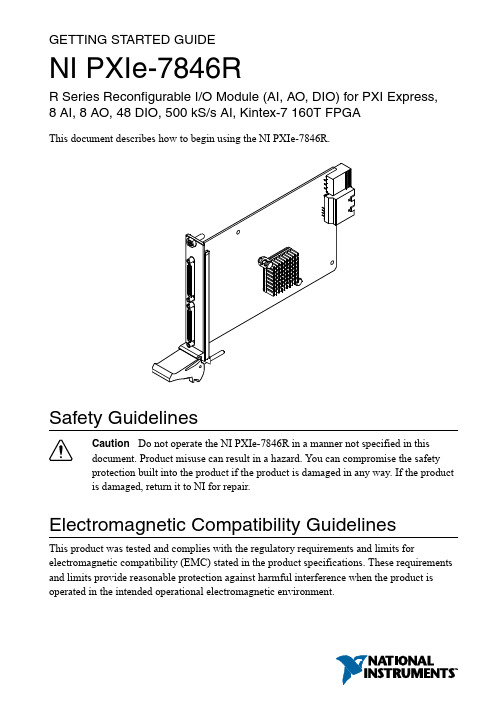
GETTING STARTED GUIDENI PXIe-7846RR Series Reconfigurable I/O Module (AI, AO, DIO) for PXI Express,8 AI, 8 AO, 48 DIO, 500 kS/s AI, Kintex-7 160T FPGAThis document describes how to begin using the NI PXIe-7846R.Safety GuidelinesCaution Do not operate the NI PXIe-7846R in a manner not specified in thisdocument. Product misuse can result in a hazard. You can compromise the safetyprotection built into the product if the product is damaged in any way. If the productis damaged, return it to NI for repair.Electromagnetic Compatibility GuidelinesThis product was tested and complies with the regulatory requirements and limits for electromagnetic compatibility (EMC) stated in the product specifications. These requirements and limits provide reasonable protection against harmful interference when the product is operated in the intended operational electromagnetic environment.This product is intended for use in industrial locations. However, harmful interference may occur in some installations, when the product is connected to a peripheral device or test object, or if the product is used in residential or commercial areas. To minimize interference with radio and television reception and prevent unacceptable performance degradation, install and use this product in strict accordance with the instructions in the product documentation.Furthermore, any changes or modifications to the product not expressly approved by National Instruments could void your authority to operate it under your local regulatory rules.Caution To ensure the specified EMC performance, operate this product only withshielded cables and accessories.Caution To ensure the specified EMC performance, the length of all I/O cablesmust be no longer than 3 m (10 ft).Preparing the EnvironmentEnsure that the environment in which you are using the NI PXIe-7846R meets the following specifications.0 °C to 55 °COperating temperature(IEC 60068-2-1, IEC 60068-2-2)Operating humidity (IEC 60068-2-56)10% RH to 90% RH, noncondensing Pollution degree2Maximum altitude2,000 mIndoor use only.Note Refer to the device specifications on /manuals for completespecifications.Unpacking the KitCaution To prevent electrostatic discharge (ESD) from damaging the device,ground yourself using a grounding strap or by holding a grounded object, such asyour computer chassis.1.Touch the antistatic package to a metal part of the computer chassis.2.Remove the device from the package and inspect the device for loose components or anyother sign of damage.Caution Never touch the exposed pins of connectors.Note Do not install a device if it appears damaged in any way.2| | NI PXIe-7846R Getting Started Guide3.Unpack any other items and documentation from the kit.Store the device in the antistatic package when the device is not in use.Verifying the Kit ContentsVerify that the following items are included in the NI PXIe-7846R kit.Figure 1. NI PXIe-7846R Kit Contents1.Hardware2.NI-RIO Media3.Getting Started GuideInstalling Software on the Host ComputerBefore using the NI PXIe-7846R, you must install the following application software and device drivers on the host computer.bVIEW 2016 or laterbVIEW Real-Time Module 2016 or later1bVIEW FPGA Module 2016 or later4.NI R Series Multifunction RIO Device Drivers August 2016 or laterVisit /info and enter the Info Code softwareversion for minimum software support information.Installing the NI PXIe-7846RCaution To prevent damage to the device caused by ESD or contamination, handlethe device using the edges or the metal bracket.1.Ensure the AC power source is connected to the chassis before installing the modules.The AC power cord grounds the chassis and protects it from electrical damage while you install the modules.1LabVIEW Real Time Module is only required when the R Series board is used in a chassis where the PXIe Controller is running a real-time operating system.NI PXIe-7846R Getting Started Guide | © National Instruments| 33.Inspect the slot pins on the chassis backplane for any bends or damage prior to installation. Do not install a module if the backplane is damaged.4.Remove the black plastic covers from all the captive screws on the module front panel.5.Identify a supported slot in the chassis. The following figure shows the symbols that indicate the slot types.Figure 2. Chassis Compatibility Symbols1.PXI Express System Controller Slot2.PXI Peripheral Slot3.PXI Express Hybrid Peripheral Slot4.PXI Express System Timing Slot5.PXI Express Peripheral SlotNI PXIe-7846R modules can be placed in PXI Express peripheral slots, PXI Express hybrid peripheral slots, or PXI Express system timing slots.6.Touch any metal part of the chassis to discharge static electricity.7.Place the module edges into the module guides at the top and bottom of the chassis. Slide the device into the slot until it is fully inserted.Figure 3. Module Installation1.Chassis2.System Controller3.Hardware Module4.Front-Panel Mounting Screws5.Module Guides6.Power Switch8.Secure the device front panel to the chassis using the front-panel mounting screws.Note Tightening the top and bottom mounting screws increases mechanicalstability and also electrically connects the front panel to the chassis, which can improve the signal quality and electromagnetic performance.9.Cover all empty slots with filler panels or use slot blockers to maximize cooling air flow.4 | | NI PXIe-7846R Getting Started GuideVerifying Hardware Installation for Host Targets You can verify that the system recognizes the NI PXIe-7846R by using Measurement & Automation Explorer (MAX).unch MAX by navigating to Start»All Programs»National Instruments»MAX or byclicking the MAX desktop icon.2.Expand Devices and Interfaces.3.Verify that the device appears under Devices and Interfaces.If the device does not appear, press <F5> to refresh the view in MAX. If the device does not appear after refreshing the view, visit /support for troubleshooting information. Verifying Hardware Installation for Remote TargetsYou can verify that the system recognizes the NI PXIe-7846R by using Measurement & Automation Explorer (MAX).unch MAX on the host computer.2.Expand Remote Targets in the configuration tree and locate your system.3.Install LabVIEW Real-Time Module 2016 and NI RIO Device Drivers August 2016 orlater on your Remote Target.a)Refer to the Installing Software on the Host Computer section for information aboutinstalling software on the host.b)Refer to the PXI Express Controllers User Manual at /manuals forinformation on installing software on the target.4.Under Remote Targets, find and expand Devices and Interfaces.If the device does not appear, press <F5> to refresh the view in MAX. If the device does not appear after refreshing the view, visit /support for troubleshooting information.NI PXIe-7846R Getting Started Guide | © National Instruments| 5PinoutCONNECTOR 1(DIO)CONNECTOR 0(MIO)Table 1. NI PXIe-7846R Signal Descriptions6 | | NI PXIe-7846R Getting Started GuideTable 1. NI PXIe-7846R Signal Descriptions (Continued)The NI PXIe-7846R is protected from overvoltage and overcurrent conditions.Note Refer to the device specifications, available at /manuals for moreinformation.NI PXIe-7846R Getting Started Guide | © National Instruments| 7Where to Go NextWorldwide Support and ServicesThe NI website is your complete resource for technical support. At /support, you have access to everything from troubleshooting and application development self-help resources to email and phone assistance from NI Application Engineers.Visit /services for NI Factory Installation Services, repairs, extended warranty, and other services.Visit /register to register your NI product. Product registration facilitates technical support and ensures that you receive important information updates from NI.A Declaration of Conformity (DoC) is our claim of compliance with the Council of the European Communities using the manufacturer’s declaration of conformity. This system affords the user protection for electromagnetic compatibility (EMC) and product safety. You can obtain the DoC for your product by visiting /certification. If your product supports calibration, you can obtain the calibration certificate for your product at /calibration. 8| | NI PXIe-7846R Getting Started GuideNI corporate headquarters is located at 11500 North Mopac Expressway, Austin, Texas, 78759-3504. NI also has offices located around the world. For telephone support in the United States, create your service request at /support or dial 1 866 ASK MYNI (275 6964). For telephone support outside the United States, visit the Worldwide Offices section of / niglobal to access the branch office websites, which provide up-to-date contact information, support phone numbers, email addresses, and current events.NI PXIe-7846R Getting Started Guide | © National Instruments| 9Refer to the NI Trademarks and Logo Guidelines at /trademarks for information on NI trademarks. Other product and company names mentioned herein are trademarks or trade names of their respective companies. For patents covering NI products/technology, refer to the appropriate location: Help»Patents in your software, the patents.txt file on your media, or the National Instruments Patent Notice at /patents. Y ou can find information about end-user license agreements (EULAs) and third-party legal notices in the readme file for your NI product. Refer to the Export Compliance Information at /legal/export-compliance for the NI global trade compliance policy and how to obtain relevant HTS codes, ECCNs, and other import/export data. NI MAKES NO EXPRESS OR IMPLIED WARRANTIES AS TO THE ACCURACY OF THE INFORMA TION CONTAINED HEREIN AND SHALL NOT BE LIABLE FOR ANY ERRORS. U.S. Government Customers: The data contained in this manual was developed at private expense and is subject to the applicable limited rights and restricted data rights as set forth in FAR 52.227-14, DFAR 252.227-7014, and DFAR 252.227-7015.© 2016 National Instruments. All rights reserved.375944B-01May16。
ICDPPCNEXUS MPC55xx MPC56xx In-Circuit Debugger
ICDPPCNEXUSMPC55xx / MPC56xx In-Circuit DebuggerQuick Start GuideCopyright 2009, P&E Microcomputer Systems, Inc. All rights reserved.Visit us on the web at Document Version HistoryVersion Date Notes1.0 21 Sep 2009 Initial versionCONTENTS1 Introduction (4)1.1 P&E Compatible Hardware (4)2 Getting Started (5)2.1 Connecting to your Target (5)2.2 Reset Script (6)2.3 Loading Data and Debug Information (7)2.4 CPU and Memory Windows (8)3 Debugging (10)3.1 GOTIL command (10)3.1 Stepping through C instructions (11)3.3 Setting and Reaching Breakpoints (12)3.4 Using Code Window Popup Debug Evaluation Hints (13)3.5 Using the Variables Window (15)3.6 Modifying a Variable (16)3.7 Using the Register Interpreter (17)3.8 Adding Register Field Descriptions to the Variables Window (20)1 IntroductionThis document is a step-by-step guide to using the P&E ICDPPCNEXUS in-circuit debugger software, which is compatible with Freescale MPC55xx / MPC56xx processors. This guide covers the most commonly used features of the debugger: loading binary & debug information, accessing CPU registers & memory, stepping code, setting breakpoints, and monitoring variables.1.1 P&E Compatible HardwareThe following lists the P&E hardware compatible with the ICDPPCNEXUS debugger software.P&E Part Number Interface to host PCCABPPCNEXUS Parallel (LPT) portUSB-ML-PPCNEXUS USB 2.0 (Backwards compatible with USB 1.1 ports) Cyclone MAX Serial (RS232) portUSB 1.1 (Upwards compatible with USB 2.0 ports)Ethernet2 Getting Started2.1 Connecting to your TargetUpon starting the debugger, the connection assistant dialog appears:•Use the “Interface” and “Port” drop-down menus to choose the P&E hardware interface connected between the PC and your target board.•The “Target CPU” setting can safely be left at the “Autodetect” setting for most users. If you experience problems connecting, you can try specifying the exact Freescale device that you are connecting to.• A BDM_SPEED parameter between 2 to 4 can typically be used.Processors running at slower clock speeds will require higher values.Click the Connect button, and ICDPPCNEXUS will attempt to contact the processor. Using the default debugger settings, ICDPPCNEXUS will establish communications and reset the processor.After establishing communications, the main debugger screen will appear, and a debugger reset script macro should automatically execute and complete.2.2 Reset ScriptThis section explains the initialization that the debugger, using a reset script macro file, performs on the processor. The user can view and modify all of the macro file's initialization tasks.The processor Boot Assist Module (BAM) would normally initialize the memory of the processor. However, when running the target application from the debugger, the BAM functionality is disabled. To account for this, the debugger must run a script file on reset. The script initializes the memory of the processor similar to the way in which the BAM would initialize the processor.If ICDPPCNEXUS is launched from the Freescale CodeWarrior IDE, the correct reset script file is automatically selected.If ICDPPCNEXUS is launched stand-alone, the reset script file may need to be configured. Several reset script macros are included with the ICDPPCNEXUS debugger and have a .mac extension. For detailed information, you can view each macro file using a simple text editor such as Notepad. The macro contents will contain useful comments, such as which devices are supported by that particular macro.To configure the debugger reset script macro, select the debugger Configuration menu, Automated Script Options dialog, shown here:2.3 Loading Data and Debug InformationIf ICDPPCNEXUS is launched from the Freescale CodeWarrior IDE, your code will automatically be downloaded to the processor.•RAM projects are loaded into the processor’s internal SRAM.•FLASH projects will invoke the CPROGPPCNEXUS Flash programming software to burn the code into the processor’s internal FLASH.The debug information is also automatically loaded from CodeWarrior, which will allow you to debug using your high level source code and variables.If ICDPPCNEXUS is launched stand-alone, you will need to manually download the code and debug information. Launch the Load Dialog by clicking on the High Level Load button on the debugger tool bar:This dialog allows you to specify the binary/debug file and whether to load into RAM or FLASH. Once you are satisfied with your settings, press the “Process Load Command” button to begin the download process. This step will also load the debug information.2.4 CPU and Memory WindowsThe CPU Window displays all CPU core registers, including the Program Counter (PC) and all general purpose registers.•To modify CPU register contents, double-click the register value. You will be prompted for a new value.The Memory Window displays data at any given memory address. It can be used to view RAM contents, FLASH contents, and values of peripheral registers.•To change the memory address, right-click inside the Memory Window and select “Set Base Address”. You will be prompted for a new address to begin displaying data.•To change the contents in memory, double-click the value in memory that you would like to change. You will be prompted for a new value.3 DebuggingThis section outlines the different debugging capabilities available in the ICDPPCNEXUS debugger once the debug information has been loaded.3.1 GOTIL commandAt this point, your source window will show the assembly language startup code generated by the compiler:If you do not need to debug this section and would like to run the processor until the beginning of your “main” function, you can use the “GOTIL” command.•Type “GOTIL main” in the Status window to tell the debugger to run code until it reaches the “main” function of your code.The “GOTIL” command works with any function in your code.3.1 Stepping through C instructionsStep through the initialization code, or any source code, using the high-level language source step command. Use this feature by typing “HSTEP” in the Status window or by clicking the high-level step button on the debugger tool bar:Each time the HSTEP command executes, the debugger will rapidly single step assembly instructions until it encounters the next source instruction, at which point target execution will cease. When the debugger reaches the next source instruction, all visible windows will be updated with data from the board. After reaching the main function, step through several C language instructions. Notice that some instructions will take longer to step through than others because each C instruction may consist of a greater or fewer number of underlying assembly instructions.3.3 Setting and Reaching BreakpointsIn the source code window, there will be a small red dot and a small blue arrow next to each source instruction that has underlying object code. If a large blue arrow appears on a source line, this indicates that the program counter (PC) currently points to this instruction. If a large red stop sign appears on the source line, this indicates that a breakpoint exists on this line.•Set a breakpoint at an instruction by double-clicking the tiny red dot.•To remove a breakpoint, double-click the large red stop sign.Execution will begin in real-time when you issue the HGO command or click the high-level language GO button on the debugger tool bar:If the debugger encounters a breakpoint, execution will stop on this source line. If it does not encounter a breakpoint, target execution will continue until you press a key or use the stop button on the debugger tool bar:•By double clicking the small blue arrow, you will be issuing a GOTIL command to the address of this source line.A GOTIL command will set a single breakpoint at the desired address, and the processor will begin executing code in real-time from the current program counter (PC). When the debugger encounters the GOTIL address, execution stops. If the debugger does not encounter this location, execution continues until you press akey or use the stop button on the debugger tool bar. Note that all user breakpoints are ignored when the GOTIL command is used.You may also double-click the red and blue symbols in the disassembly window. The disassembly window may display an additional symbol, a small, blue "S" enclosed in a box. This indicates that that a source code instruction begins on this disassembly instruction.3.4 Using Code Window Popup Debug Evaluation HintsWhen debugging source code, it is convenient to view the contents of a variable while viewing your source code. The in-circuit debugger has a feature, debug hints, which displays the value of a variable while the mouse cursor is held over the variable name. The hint may be displayed in any of three locations, as shown below.The three locations for the debug hints are the code window title bar, the status window caption bar, and a popup hint that appears over the variable in source code. You can configure the hints to display in any combination.•Set the locations of debug hints in the configuration menu of the debuggerThe information in the popup hint box is similar to the information displayed in the variables window.The information includes the variable name (i), value ($1), and type (signed long).3.5 Using the Variables WindowThe variables window displays the current value of application variables. The following window shows a display of variables from the example application.Variables that are pointer or reference types are displayed in red. Normal variables are displayed in black.•Add a variable by typing the VAR command, by right clicking the variables window and choosing “Add a variable”, or by hitting the "Add Variable"button in the variables window.When adding a variable using the pop-up menu, the debugger displays the following screen.In the variable field, type the address or name of the variable. Typically, set the type of the variable to “Default”, which means that the variable will be displayed as it is defined in the debugging information. When adding a variable, you may specify the numeric display base of the variable.3.6 Modifying a Variable•To modify the current value of a variable, right-click the variable name in the variables window and select “Modify Variable” to display a dialog.Check the “Modify value” checkbox, and type the variable’s new value. After you click the OK button, the debugger updates the variable value on the target, and the debugger refreshes the variable window to display the new value. Note that the debugger will not edit certain user-defined types, such as enumerated types.•You may also modify a variable’s display properties, such as the type or numeric display base using this dialog.3.7 Using the Register InterpreterThe register interpreter provides a descriptive display of bit fields within the processor’s peripheral registers. The register interpreter allows you easily to change the value of these registers. You may quickly check the current state of a peripheral and examine the configuration of the target device.When you use the register interpreter within the debugger, it reads the current value of the peripheral register, decodes it, and displays it.To launch the register interpreter in the debugger, either use the “R” command or click the view/edit register button on the tool bar:A window will appear that allows you to select a peripheral block to examine.Double clicking the module of choice will launch the register selection window.Double clicking a specific register will launch the edit/display window for that register.The window lists the keystrokes and mouse actions, allowing you to modify the values of each of the fields. After right clicking on a specific field, the register interpreter will display all options for that field.When you quit the register view/edit window by hitting the ESC key, you will be given the opportunity to write the new value into the register, as shown in the following window.3.8 Adding Register Field Descriptions to the Variables WindowAdd register bit fields to the variables window by using the “_TR” command in the debugger or by clicking the "Add Register" button in the variables window. After selecting the register field, the field appears in the debugger variables window, and the debugger will continually update its value.。
PCS7 深入浅出(第七章)

第7章:创建功能块 - SCL目录:第7章 创建功能块 - SCL (3)第7章 创建功能块 - SCL (3)1.SCL 中的块 (3)1.1 块的结构 (3)1.2 块头 (4)1.2.1 FUNCTION_BLOCK (4)1.2.2 TITLE (5)1.2.3 NAME (7)1.2.4 VERSION (7)1.2.5 FAMIL Y (7)1.2.6 AUTHOR (8)1.2.7 KNOW_HOW_PROTECT (8)1.3 块属性 (8)1.3.1 系统属性 (8)1.3.2 块属性列表 (9)1.3.3 定义块的属性 (10)1.4 声明区 (12)1.4.1 块参数(块I/O) (12)1.4.2 参数的系统属性列表 (13)1.4.3 局部变量 (15)1.5 代码区 (17)2.调整系统属性 (18)3.SCL 编辑器 (21)3.1 插入块模板 (21)3.2 在SCL源程序中插入块调用 (22)3.3 SCL 控制语句 (23)3.3.1 IF语句 (23)3.3.2 CASE 语句 (23)3.3.3 FOR 语句 (25)3.3.4 WHILE 语句 (25)4.块中图 (26)5.CPU 鲁棒性和检查 (30)5.1 下载整个程序,还是部分下载程序? (30)5.2 本地数据 (31)5.2.1 本地数据的定义 (31)5.2.2 预置CPU的本地数据 (31)5.2.3 本地数据的计算 (33)5.3 CPU内存 (34)5.4 对CPU负荷和内存的系统支持 (36)5.4.1 警戒限 (36)5.4.2 可用日志 (38)5.4.3 在编译期间的检查 (39)5.4.4 下载期间的措施 (39)5.4.5 进一步检查 (40)练习 (42)练习 (42)练习 7.1 在SCL中创建功能块 Rotation (42)1. 任务 (42)2. 指南 (43)练习 7.2 使用块内图创建功能块 (44)1. 任务 (44)2. 指南 (46)答案 (47)答案 (47)1. Rotation 功能的代码 (47)2. 图:带有I/O的 CTRL_P (48)第7章 创建功能块 - SCL在第6章中我们已经讨论过,可以使用LAD、STL和SCL创建功能块类型。
毕业设计4EMC系列单片机原理及应用技术
第一章 EM78系列单片机简介台湾义隆公司推出的八位EM78系列单片机已有多年,并广泛应用在家用电器、工业控制、仪器等方面,其优良的单片机结构和性能为用户所认同,但与AT89系列、PIC系列、Z86系列、GMS97系列等单片机比较而言,EM78系列单片机进入内地市场稍晚一些,所以一般人并不太了解。
本章将对EM78系列单片机的主要特点作一个概述,供大家参考(以EM78X56为例)。
一、先进的单片机结构EM78系列单片机将众多功能集于一身,这其中包括ALU、ROM、RAM、I/O、堆栈、中断控制器、定时/计数器、看门狗、电压检测器、复位电路、振荡电路等,成为真正意义上的单片机小系统。
二、优越的数据处理性能EM78系列单片机采用RISC结构设计、单周期、单字节及流水线指令、五级堆栈、RAM 数量从32~157个,最短指令周期100ns,程序页面为1K(多至4页),与其它一些单片机相比,EM78系列单片机具有更高、更快的运行处理速度。
三、强大的单片机新功能这包括:①三个中断源:定时器中断、I/O唤醒中断、外部信号输入中断②R-OPTION功能:如果用户程序有几个版本,希望能放在同一ROM内,则通过R-OPTION 功能便可实现此想法,R-OPTION功能设置是在相关I/O上上拉或下拉电阻,通过判断相关I/O的状态来选择执行内部何种版本程序。
③内置电压检测器:当电源电压掉在一额定值以下时单片机始终处于复位状态,以此提高系统的复位性能。
④低功耗设计:正常工作电流2mA、休眠状态电流1μA⑤多功能I/O口:可程序设置为I/O上拉、下拉、开路等方式⑥I/O唤醒功能:通过I/O变化唤醒处于休眠状态的单片机⑦内置看门狗定时器:提高单片机抗干扰能力四、灵活的功能选择设计通过软件分别设置:①指令周期的时钟周期数(2/4)②特殊指令的指令周期数(1/2)③振荡方式(内部RC、外部RC 、XTAL低频、XTAL高频等)④R-OPTION功能开/关⑤WDT开/关五、通俗易懂的指令系统EM78系列单片机指令系统采用与大家熟知的MCS-51指令风格设计,共计58条指令,大家通过较短的时间便能掌握运用。
MPLAB Xpress PIC16F18446评估板用户指南说明书

MPLAB® Xpress PIC16F18446 MPLAB® Xpress PIC16F18446 Evaluation Board PrefaceThe MPLAB® Xpress PIC16F18446 evaluation kit is a hardware platform to evaluate the PIC16F18446 microcontroller. The MPLAB® Xpress PIC16F18446 board contain two sections; the programmer section and the application section. The programmer section contains the circuitry necessary for programming, while the application section contains the circuitry that is used by the microcontroller application.MPLAB® Xpress PIC16F18446Table of Contents Preface (1)1.Introduction (3)1.1.Features (3)1.2.Kit Overview (3)2.Getting Started (4)2.1.MPLAB® Xpress Quick Start (4)2.2.Design Documentation and Relevant Links (7)3.Hardware User Guide (8)3.1.Power Supply (8)3.2.Connectors (9)3.2.1.MPLAB® Xpress PIC16F18446 Pinout (9)3.3.Peripherals (10)3.3.1.LED (10)3.3.2.Mechanical Buttons (10)3.3.3.Crystal (10)4.Embedded Debugger Implementation (12)4.1.ICSP (12)4.2.Virtual COM Port (12)5.Hardware Revision History (13)5.1.Identifying Product ID and Revision (13)5.2.Revision 1 (13)6.Document Revision History (14)7.Appendix (15)The Microchip Web Site (16)Customer Change Notification Service (16)Customer Support (16)Microchip Devices Code Protection Feature (16)Legal Notice (17)Trademarks (17)Quality Management System Certified by DNV (18)Worldwide Sales and Service (19)1.Introduction1.1Features•PIC16F18446 microcontroller •One yellow user LED•One mechanical user button •nEDBG–Programming–Virtual COM port (CDC)–One green board status LED •USB powered1.2 Kit OverviewThe Microchip MPLAB ®Xpress PIC16F18446 evaluation board is a hardware platform to evaluate the Microchip PIC16F18446.Figure 1-1. MPLAB ®Xpress PIC16F18446 Evaluation Board OverviewIntroduction2. Getting Started2.1 MPLAB® Xpress Quick StartThe Xpress Evaluation Boards are designed to work with the MPLAB® Xpress IDE, but can also be used with MPLAB® X IDE. MPLAB Xpress IDE does not require any downloads and can be accessed byvisiting . The Xpress Evaluation Boards allow for rapid development ofcustom applications without the need to download the IDE or compilers to a computer and allows thestorage of a project in the cloud. This allows a user the ability to access their project from virtuallyanywhere (requires an Internet connection) and from any computer. Microchip also provides codeexamples to help get you started.Programming the Xpress board is accomplished by connecting a Micro-USB cable to the onboard USBconnector, creating the .hex file, and dragging and dropping the .hex file into the Xpress board.To begin, connect a Micro-USB cable to the onboard USB connector. Next, open the MPLAB Xpress IDE.The procedure to create a new project or open an existing MPLAB Xpress project is the same as withinMPLAB X IDE. Navigate to the File tab, select Project Properties > Configuration > Hardware Tool >Hardware Tools and select ‘Simulator/Xpress Board’ (see Figure 2-1). This ensures that the Xpress board is chosen as the development tool. Once selected, the ‘Simulator/Xpress Board’ selection will appearunder the ‘Debug Tool’ section in the Dashboard window (see Figure 2-2).Once the project is open and ready to program into the target device, simply click on the Make andProgram Device button (see Figure 2-3).MPLAB Xpress will build and compile the project, and once completed, will open or save the .hex file that was created. Under the Save button, you can either hit Save and the .hex file will be stored in yourdownloads folder, or you can hit Save as and choose the location for the .hex file. It is important toremember where the file is stored since the .hex file is what will be programmed into the target PIC®device.Figure 2-1. Selecting the Xpress Kit in MPLAB® Xpress IDEFigure 2-2. Selecting the Xpress Kit in MPLAB® Xpress IDE (Cont)Figure 2-3. Make and Program Device2.2 Design Documentation and Relevant LinksThe following list contains links to the most relevant documents and software for the MPLAB® XpressPIC16F18446.•Microchip sample store - Microchip sample store where you can order samples of devices.•MPLAB Xpress PIC16F18446 website- Kit information, latest user guide and design documentation.•MPLAB® X IDE - MPLAB X IDE is a software program that runs on a PC (Windows®, Mac OS®, Linux®) to develop applications for Microchip microcontrollers and digital signal controllers. It iscalled an Integrated Development Environment (IDE) because it provides a single integrated"environment" to develop code for embedded microcontrollers.•MPLAB® Xpress Cloud-based IDE - MPLAB® Xpress Cloud-Based IDE is an online development environment that contains the most popular features of our award-winning MPLAB X IDE. Thissimplified and distilled application is a faithful reproduction of our desktop-based program, whichallows users to easily transition between the two environments.to generate 3.3V on MPLAB ®Xpress PIC16F18446.If an external voltage is required, the power supply and the target must be separated. This can be done by cutting the strap on the bottom side of the kit marked VREG as shown in the figure below. Cutting the strap will not separate the target supply from the level shifter, allowing programming of the PIC16F18446with an external voltage.Supplying external power to the board while the USB cable is plugged in, without cutting the VREG strap, can permanently damage the toolkit and the USB port of the PC.Figure 3-1. Power Supply Block DiagramCut strapPower converterFigure 3-2. nEDBG Cut Straps3.2 Connectors3.2.1 MPLAB® Xpress PIC16F18446 PinoutMPLAB® Xpress PIC16F18446 has most of it's I/O's accessible at the edge connectors. Some I/O's are connected to the nEDBG for programming and communication purposes.Table 3-1. Edge Connector3.3 Peripherals3.3.1 LEDThere is one yellow LED available on the MPLAB® Xpress PIC16F18446 board that can be turned ONand OFF. The LED can be activated by driving the connected I/O line to GND.Table 3-2. LED Connection3.3.2 Mechanical ButtonsMPLAB® Xpress PIC16F18446 contains one mechanical button. This is a generic user configurablebutton and when a button is pressed it will drive the I/O line to GND.Info: There is no pull-up resistor connected to the generic user button. Remember to enablethe internal pull-up in the PIC16F18446 to use the button.Table 3-3. Mechanical Button3.3.3 CrystalThe MPLAB® Xpress PIC16F18446 board has a 32768 Hz crystal mounted on the board.Hardware User Guide The crystal is not connected to the PIC16F18446 by default, as the GPIO's are routed out to the edge connector. To use the crystal, some hardware modifications are required. The two I/O lines routed to the edge connector should be disconnected to both reduce the chance of contention to the crystal as well as removing excessive capacitance on the lines. This can be done by cutting the two straps on the bottom side of the board, marked RA4 and RA5 as shown in the figure below. Next, solder on a solder blob on each of the circular solder points next to the crystal on the top side of the board as shown in the figure below.The 32.768 kHz crystal on MPLAB® Xpress PIC16F18446 is a Kyocera CorporationST3215SB32768C0HPWBB 7 pF crystal.The crystal has been formally tested and matched to the PIC16F18446 by Kyocera. The test report is available in the design documentation distributed with this document for MPLAB® Xpress PIC16F18446.Info: Kyocera Crystal Device Corporation crystals that are matched with specific products canbe found on their website: http://prdct-search.kyocera.co.jp/crystal-ic/?p=en_search/Table 3-4. Crystal ConnectionsFigure 3-3. Crystal Connection and Cut StrapsEmbedded Debugger Implementation4. Embedded Debugger ImplementationMPLAB® Xpress PIC16F18446 contains an embedded debugger (nEDBG) that can be used to programthe PIC16F18446 using ICSP.The nEDBG can program the PIC16F18446 with a USB mass storage drive and also include a VirtualCOM Port interface over UART.4.1 ICSPThe In-Circuit Serial Program (ICSP) interface use three pins to communicate with the target.Info: There is a 10 kΩ pull-up resistor connected to RA3 and there are 47 kΩ pull-downresistors connected to RA0 and RA1.Table 4-1. ICSP Connections4.2 Virtual COM PortThe nEDBG acts as a Virtual COM Port gateway by using one of the PIC16F18446 UARTs.The Virtual COM Port is connected to a UART on the PIC16F18446 and provides an easy way tocommunicate with the target application through terminal software. It offers variable baud rate, parity, and stop bit settings. The settings on the PIC16F18446 must match the settings given in the terminalsoftware.Info: The Virtual COM Port in the nEDBG requires the terminal software to set the DataTerminal Ready (DTR) signal to enable the UART pins. If the DTR signal is not enabled, theUART pins on the nEDBG are kept in tri-state (high-z) to render the COM Port not usable. TheDTR signal is automatically set by some terminal software, but it may have to be manuallyenabled in your terminal.Table 4-2. Virtual COM Port Connections5. Hardware Revision HistoryThis user guide provides the latest available revision of the kit. This chapter contains information aboutknown issues, a revision history of older revisions, and how older revisions differ from the latest revision.5.1 Identifying Product ID and RevisionThe revision and product identifier of MPLAB® Xpress PIC16F18446 can be found in two ways; eitherthrough Atmel Studio/Microchip MPLAB X or by scanning sticker on the bottom side of the PCB with a 2D barcode reader.By connecting a MPLAB® Xpress PIC16F18446 to a computer with Atmel Studio/Microchip MPLAB Xrunning, an information window will pop up. The first six digits of the serial number, which is listed under kit details, contain the product identifier and revision.The same information can be found on the sticker on the bottom side of the PCB. Most kits will print theidentifier and revision in plain text as A09-nnnn\rr, where nnnn is the identifier and rr is the revision.Boards with limited space have a sticker with only a data-matrix barcode, which contains a serial number string.The serial number string has the following format:"nnnnrrssssssssss"n = product identifierr = revisions = serial numberThe product identifier for MPLAB® Xpress PIC16F18446 is A09-3160.5.2 Revision 1Revision 1 is the initially released revision.6. Document Revision HistoryAppendix 7. AppendixFigure 7-1. MPLAB® Xpress PIC16F18446 SchematicsThe Microchip Web SiteMicrochip provides online support via our web site at /. This web site is used as a means to make files and information easily available to customers. Accessible by using your favorite Internet browser, the web site contains the following information:•Product Support – Data sheets and errata, application notes and sample programs, design resources, user’s guides and hardware support documents, latest software releases and archived software•General Technical Support – Frequently Asked Questions (FAQ), technical support requests, online discussion groups, Microchip consultant program member listing•Business of Microchip – Product selector and ordering guides, latest Microchip press releases, listing of seminars and events, listings of Microchip sales offices, distributors and factoryrepresentativesCustomer Change Notification ServiceMicrochip’s customer notification service helps keep customers current on Microchip products. Subscribers will receive e-mail notification whenever there are changes, updates, revisions or errata related to a specified product family or development tool of interest.To register, access the Microchip web site at /. Under “Support”, click on “Customer Change Notification” and follow the registration instructions.Customer SupportUsers of Microchip products can receive assistance through several channels:•Distributor or Representative•Local Sales Office•Field Application Engineer (FAE)•Technical SupportCustomers should contact their distributor, representative or Field Application Engineer (FAE) for support. Local sales offices are also available to help customers. A listing of sales offices and locations is included in the back of this document.Technical support is available through the web site at: /supportMicrochip Devices Code Protection FeatureNote the following details of the code protection feature on Microchip devices:•Microchip products meet the specification contained in their particular Microchip Data Sheet.•Microchip believes that its family of products is one of the most secure families of its kind on the market today, when used in the intended manner and under normal conditions.•There are dishonest and possibly illegal methods used to breach the code protection feature. All of these methods, to our knowledge, require using the Microchip products in a manner outside the operating specifications contained in Microchip’s Data Sheets. Most likely, the person doing so is engaged in theft of intellectual property.•Microchip is willing to work with the customer who is concerned about the integrity of their code.•Neither Microchip nor any other semiconductor manufacturer can guarantee the security of their code. Code protection does not mean that we are guaranteeing the product as “unbreakable.”Code protection is constantly evolving. We at Microchip are committed to continuously improving the code protection features of our products. Attempts to break Microchip’s code protection feature may be a violation of the Digital Millennium Copyright Act. If such acts allow unauthorized access to your software or other copyrighted work, you may have a right to sue for relief under that Act.Legal NoticeInformation contained in this publication regarding device applications and the like is provided only for your convenience and may be superseded by updates. It is your responsibility to ensure that your application meets with your specifications. MICROCHIP MAKES NO REPRESENTATIONS OR WARRANTIES OF ANY KIND WHETHER EXPRESS OR IMPLIED, WRITTEN OR ORAL, STATUTORY OR OTHERWISE, RELATED TO THE INFORMATION, INCLUDING BUT NOT LIMITED TO ITS CONDITION, QUALITY, PERFORMANCE, MERCHANTABILITY OR FITNESS FOR PURPOSE. Microchip disclaims all liability arising from this information and its use. Use of Microchip devices in life support and/or safety applications is entirely at the buyer’s risk, and the buyer agrees to defend, indemnify and hold harmless Microchip from any and all damages, claims, suits, or expenses resulting from such use. No licenses are conveyed, implicitly or otherwise, under any Microchip intellectual property rights unless otherwise stated.TrademarksThe Microchip name and logo, the Microchip logo, AnyRate, AVR, AVR logo, AVR Freaks, BeaconThings, BitCloud, CryptoMemory, CryptoRF, dsPIC, FlashFlex, flexPWR, Heldo, JukeBlox, KeeLoq, KeeLoq logo, Kleer, LANCheck, LINK MD, maXStylus, maXTouch, MediaLB, megaAVR, MOST, MOST logo, MPLAB, OptoLyzer, PIC, picoPower, PICSTART, PIC32 logo, Prochip Designer, QTouch, RightTouch, SAM-BA, SpyNIC, SST, SST Logo, SuperFlash, tinyAVR, UNI/O, and XMEGA are registered trademarks of Microchip Technology Incorporated in the U.S.A. and other countries.ClockWorks, The Embedded Control Solutions Company, EtherSynch, Hyper Speed Control, HyperLight Load, IntelliMOS, mTouch, Precision Edge, and Quiet-Wire are registered trademarks of Microchip Technology Incorporated in the U.S.A.Adjacent Key Suppression, AKS, Analog-for-the-Digital Age, Any Capacitor, AnyIn, AnyOut, BodyCom, chipKIT, chipKIT logo, CodeGuard, CryptoAuthentication, CryptoCompanion, CryptoController, dsPICDEM, , Dynamic Average Matching, DAM, ECAN, EtherGREEN, In-Circuit Serial Programming, ICSP, Inter-Chip Connectivity, JitterBlocker, KleerNet, KleerNet logo, Mindi, MiWi, motorBench, MPASM, MPF, MPLAB Certified logo, MPLIB, MPLINK, MultiTRAK, NetDetach, Omniscient Code Generation, PICDEM, , PICkit, PICtail, PureSilicon, QMatrix, RightTouch logo, REAL ICE, Ripple Blocker, SAM-ICE, Serial Quad I/O, SMART-I.S., SQI, SuperSwitcher, SuperSwitcher II, Total Endurance, TSHARC, USBCheck, VariSense, ViewSpan, WiperLock, Wireless DNA, and ZENA are trademarks of Microchip Technology Incorporated in the U.S.A. and other countries.SQTP is a service mark of Microchip Technology Incorporated in the U.S.A.Silicon Storage Technology is a registered trademark of Microchip Technology Inc. in other countries. GestIC is a registered trademark of Microchip Technology Germany II GmbH & Co. KG, a subsidiary of Microchip Technology Inc., in other countries.All other trademarks mentioned herein are property of their respective companies.© 2018, Microchip Technology Incorporated, Printed in the U.S.A., All Rights Reserved.ISBN: 978-1-5224-2727-8Quality Management System Certified by DNVISO/TS 16949Microchip received ISO/TS-16949:2009 certification for its worldwide headquarters, design and wafer fabrication facilities in Chandler and Tempe, Arizona; Gresham, Oregon and design centers in California and India. The Company’s quality system processes and procedures are for its PIC® MCUs and dsPIC®DSCs, KEELOQ® code hopping devices, Serial EEPROMs, microperipherals, nonvolatile memory and analog products. In addition, Microchip’s quality system for the design and manufacture of development systems is ISO 9001:2000 certified.Worldwide Sales and Service。
- 1、下载文档前请自行甄别文档内容的完整性,平台不提供额外的编辑、内容补充、找答案等附加服务。
- 2、"仅部分预览"的文档,不可在线预览部分如存在完整性等问题,可反馈申请退款(可完整预览的文档不适用该条件!)。
- 3、如文档侵犯您的权益,请联系客服反馈,我们会尽快为您处理(人工客服工作时间:9:00-18:30)。
第七章 PIC程序转换至EM78XX 武汉威帆 (027)87644346
第七章 PIC程序转换至EM78XX
7.1.芯片对照
PIC其中一些单片机与EM78系列单片机管脚相兼容,对照如下:
12C508/509 ——EM78P152/153
PIC16C54/56/84——EM78P156/256/456
PIC16C55/57 ——EM78P447
以上单片机转换可以在不用改动PCB情况便可完成,具体硬件资源对照如表7.1所示.
7.2.指令对照表
指令对照表如表7.2所示
7.3.转换软件使用说明
现有转换软件X156M.EXE可以将PIC编写的程序目标码转成EM78单片机可用的源代
码。
文件名:X156M.EXE
说明:PIC程序文件名后缀一定是(.OBJ)
文件格式是16进制(HEX)或二进制(BIN)
执行X156M(以5XDEMO.OBJ为例、HEX格式)
提示输入文件5XDEMO.OBJ
询问是何种文件格式(H/B)?选H
询问文件大小(单位是512字节)?输入1或2(视文件大小而定)
询问文件输出方式(0/1)?选1
询问WDT开/关否?(视情况而定)
至此,可输出名为5XDEMO.DT文件(即EM78XX的源程序)
注:经过上述转换的程序仍可能存在下列问题,需要修正:
1、针对EMC内部RAM地址比PIC高10H,转换程序对RAM地址硬性加10H,如此时R4
则转为R14,如果R4作间接寻址用,此时应恢复R14——R4;在间接寻址中,在赋给R4立即数的值转到EMC时该立即数也应加10H.
2、PIC和EMC个别寄存器如标志寄存器R3.7、R4不一样,有些PIC程序中用了其中闲
置的bit做标志位,到EMC程序中要检查有没有冲突。
3、PIC和EMC读入RA或口5,闲置位赋值不一样:如PIC16C54读RA.时RA的高四位
为0,但EM78×56就不是为0,所以EM78X56读出口5数据时要屏蔽高位,否则容易出错。
4、针对PIC16C57程序转换的问题,由于X156M暂时转换文件最大为1K,所以折中的办
法是将16c57的2K程序拆分成两个1K,类似上述三点再比照16C57和447的寄存器区别,便可较快转换程序。
第126 页
第七章 PIC程序转换至EM78XX 武汉威帆 (027)87644346
第127 页
第七章 PIC程序转换至EM78XX 武汉威帆 (027)87644346
表7.2 PIC与EMC指令对照表
第128 页。