dec110e8-aa01-4dd0-99ca-4febaddb5c99
派克液压密封件说明书

派克汉尼汾公司版权所有未经许可不能摘录,翻印。
保留修改权利2021年6月警告销售条件本样本中产品和/或系统或相关产品出现故障,选型不当或使用不当,均可能导致人身伤亡和财产损失。
本文档以及由派克·汉尼汾公司及其子公司和授权经销商提供的其他资料,为具有技术知识的用户提供进一步研究所需的产品和/或系统选项。
重要的是,用户必须对您的应用进行全面的分析,并对当前产品样本中与产品或系统相关的资料进行评估。
由于工作条件以及产品或系统的多样性,用户必须自行分析和测试,并独自承担一切后果,包括:产品和系统的最终选型以及确保满足应用的所有性能、安全和警告等方面的要求。
派克·汉尼汾及其子公司可能会随时对本样本中的产品,包括但不限于:产品的特性、产品的规格、产品的结构、产品的有效性以及产品的价格作出变更而不另行通知.本样本中的所有产品均由派克·汉尼汾公司及其子公司和援权经销商销售。
与派克签订的任何销售合同均按照派克标准条件和销售条件中规定的条款执行(提供复印件备索)。
本公司的密封件,只能在本公司的文件资料述及的应用参数范围与接触介质、压力、温度和存放时间相一致的情况下才能使用。
在规定的应用参数范围外使用以及错误选用不同的材料都可能导致密封件寿命的缩短以及设备的损坏,甚至更严重的后果(如生命安全,环境污染等)。
样本中所列出的工作压力、温度范围、运动速度是极限值,它们之间相互关联、相互影响;在极端的工况下,建议不要同时把各个参数都同时用到极限值。
对于特殊的要求(压力、温度、速度、介质等),请联系派克汉尼汾公司以咨询合适的密封结构、材料、配置、安装建议等。
由于诸多工作参数会影响到流体传动系统及密封元件,这些设备的制造商必须在实际工作条件下测试、验证并批准密封系统的功能与可靠性。
此外,对于不断出现的新的介质(液压油、润滑脂、清洗剂等),用户特别注意它们与目前所用的密封件弹性体材料的兼容性。
我们建议用户在大批量应用之前,在厂内或现场先做密封材料的兼容性能测试,作为密封产品与系统供应商,我们建议用户遵循我们的这些建议。
汽车常见EEPROM芯片

汽车常见EEPROM芯片就汽车上常见的EEPROM芯片按其接口方式来分,无外乎有I2C、Microwire、SPI三种,但每一种芯片又分为各种容量规格,比如I2C中的24C01、24C02、24C04,一般尾数大的比尾数小的容量大,且有着直接的倍数关系。
其中汽车音响用的芯片种类最多、最杂,从I2C的24C01-24C16,Microwire的93C06到93C56,现在出的音响还用到SIP的25160,而且Mirowire的93C46系列还分为标准与非标准,二者主要体现在引脚分布上,其内部功能基本一致。
使用时须仔细区分,否则出现读写不了数据还误认为芯片损坏,主要是日本的汽车音响会用到这种芯片,欧美的音响基本不采用这种“非准”芯片。
另外还有一种S130和S220的芯片,它们分别对应93C46和93C56,在欧洲产的音响还会经常见到85C52的芯片,通常为贴片封装,外型比一般的贴片芯片要宽一些,它和24C02基本一样,但其第7脚的写保护和24C02的写保护引脚电位状态是反的,85C52是高电位有效。
在较老的奔驰音响还可常见到BAW574252,它也是和24C01一样的,24C01有的芯片会出现能读不能写数据的情况,这时可用一片新的24C01或24C02代替。
24C02可完全兼容24C01所有功能。
在液晶仪表上用的芯片相对来说就要规范得多,大多采用Microwire,从93C46到93C86都有采用,基本上没有“非标准”芯片,且大多采用16bit结构,读取数据时须注意是16bit还是8bit,否则会出现高低位颠倒甚至数据错误的结果,这是调表须特别注意的事。
在新款的奔驰也常见24C04和B58芯片,B58可以用93C66代替。
但读写数据时,须把第七脚置为低电位。
稍老的宝马常用到CS56、CS66,它们也须把第七脚置为低电位。
在国产的仪表还用到SPI的25010和X25043(X5043),上海别克和时超用的A TMEL68343A,其实就是25010。
汽车OBDII故障码大全(五)
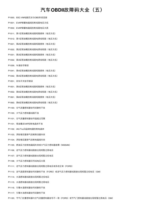
汽车OBDII故障码⼤全(五)P1000;EEC-VM电脑⽆法与OBD系统连接P1001;EVAP碳罐电磁阀控制线路电压太低P1002;EVAP碳罐电磁阀控制线路电压太⾼P1011;第1缸喷油嘴控制线路短路搭铁(电压太低)P1012;第1缸喷油嘴控制线路电源线短路(电压太低)P1021;第2缸喷油嘴控制线路短路搭铁(电压太低)P1022;第2缸喷油嘴控制线路电源线短路(电压太低)P1031;第3缸喷油嘴控制线路短路搭铁(电压太低)P1032;第3缸喷油嘴控制线路电源线短路(电压太低)P1039;车速信号错误P1041;第4缸喷油嘴控制线路短路搭铁(电压太低)P1042;第4缸喷油嘴控制线路电源线短路(电压太低)P1051;刹车开关信号错误P1051;第5缸喷油嘴控制线路短路搭铁(电压太低)P1052;第5缸喷油嘴控制线路电源线短路(电压太低)P1061;第6缸喷油嘴控制线路短路搭铁(电压太低)P1062;第6缸喷油嘴控制线路电源线短路(电压太低)P1100;空⽓流量感知器信号间歇性不良P1100;⼤⽓压⼒感知器线路不良P1101;空⽓流量感知器信号值超过范围P1101;喷油嘴/EVAP控制电晶体不良P1102;IAC/Tcc风扇继电器控制电晶体P1103;涡轮增压器排⽓控制致动器失效P1104;涡轮增压器排⽓控制电磁阀失效P1105;燃油压⼒控制电磁阀失效或⼤⽓压⼒感知器故障(NISSAN)P1106;进⽓压⼒感知器线路曾出现短暂过⾼电压P1107;进⽓压⼒感知器线路曾出现短暂过低电压P1108;⼤⽓压⼒感知器讯号线电压太⾼P1111;进⽓压⼒感知器线路曾出现短暂过⾼电压或系统正常(FORD)P1112;进⽓温度感知器信号间歇性不良(FORD)或进⽓压⼒感知器线路曾出现短暂过低电压(GM)P1114;⽔温感知器线路曾出现短暂过低电压P1115;⽔温感知器线路曾出现短暂过⾼电压P1116;引擎⽔温感知器信号间歇性不良P1117;引擎⽔浊感知器信号间歇性不良P1120;节⽓门位置感知器与空⽓流量感知器信号不⼀致(FORD)或节⽓门感知器线路曾出现短暂过⾼电压(GM)P1122;节⽓门感知器线路曾出现短暂过低电压P1124;节⽓门位置感知器信号测试错误P1125;节⽓门位置感知器信号间歇性不良或辅助节⽓门感知器系统线路操作不良(GM)P1127;在作KOER测试时,加热式含氧感知器没作⽤P1128;加热式含氧感知器信号交换P1129;加热式含氧感知器信号交换P1130;触媒前含氧感知器线路不良,燃料回馈控制系统正常(B1)P1132;触媒前含氧感知器线路不良,且感知器讯号指⽰浓度混合⽐(B1)P1133;含氧感知器(包括热线式含氧感知器)线路或感知本⾝不良或电压值超过电脑设定值P1134;含氧感知器(包括热线式含氧感知器)线路或感知本⾝不良或电压值超过电脑设定值P1135;点⽕开关讯号间歇性不良或电压值不正确P1137;触媒后含氧感知器线路不良,感知器讯号指⽰稀混合⽐(B1)P1138;触媒后含氧感知器线路不良,且感知器讯号指⽰浓混合⽐(B1)P1150;触媒后含氧感知器线路不良,但燃料回馈控制系统正常(B2)P1151;触媒后含氧感知器线路不良,且感知器讯号指⽰稀混合⽐(B2)P1152;触媒后含氧感知器线路不良,且感知器讯号指⽰浓混合⽐(B2)P1157;触媒后含氧感知器线路不良,且感知器讯号指⽰浓混合⽐(B2)P1158;触媒后含氧感知器线路不良,且感知器讯号指⽰浓混合⽐(B2)P1162;主含氧感知线路不良P1163;主含氧感知器电压变化过慢P1164;主含氧感知器不良P1165;主含氧感知器不良P1167;主含氧感知器加热不良P1168;主含氧感知器LABEL输⼊过低P1169;主含氧感知器LABEL输⼊过⾼P1170;混合⽐太浓/太稀/漏⽓/漏油或加热式含氧感知器输出电压⽆变化(FORD)P1171;加速增浓时混合⽐太稀P1172;空⽓流量计讯号电压值不正确,以致于混合⽐调整太稀P1173;空⽓流量计讯号电压值不正确,以致于混合⽐调整太浓P1187;机油温度感知器线路电压太低P1188;机油温度感知器线路电压太⾼P1195;⼤⽓压⼒感知器线路不良(信号从EGR感知器传出)P1196;起动开关线路不良P1200;喷油泵浦继电器线路不良P1200;喷油嘴控制线路不良。
德力西 DOP-110CS 触摸屏 说明书

DOP -110CSHigh color ‧Wide screen ‧User-friendlyDelta Electronics, Inc.No.18, Xinglong Rd., Taoyuan City33068, TaiwanInstruction Sheet(1) General precautionsThank you for purchasing this product. This instruction sheet provides information about the DOP-100 series HMI. Before using this product, please read through this instruction sheet carefully to ensure the correct use of the product. Please keep this sheet handy for quick reference whenever needed. Before finishing reading this sheet, please follow the instructions below: ⏹ Install the product in an indoor location, which is free of vapor, corrosive and inflammable gas and liquids.⏹ Please refer to the wiring diagram when connecting the wires.⏹ Ensure your HMI is correctly grounded. The grounding method must comply with the national electrical standard (please refer to NFPA 70: National Electrical Code, 2005 Ed.). ⏹ Do not disassemble the HMI or change the wiring when power is on.⏹ Do not touch the power supply when power is on, or it may cause electric shock.⏹ When the HMI displays a low power notification and requires a battery change, please contact your local distributor or Delta Customer Service Center for the replacement. Do not change the batteries by yourself.⏹ This product can be used with other industrial automation equipment. Please read through this sheet carefully and install the product according to the instructions to avoid danger. ⏹ Cleaning method: please use a dry cloth to clean the product. ⏹ This product must be used at an altitude below 2,000 m.⏹ If the equipment is used in a manner not specified by the manufacturer, the protection provided by the equipment may be impaired.⏹For repair and maintenance, please contact Delta Electronics, Inc. Address: No.18, Xinglong Rd., Taoyuan City, Taiwan. TEL: +886-3-3626301.If you have any inquiry during operation, please contact our local distributors or Delta salesrepresentatives. The content of this instruction sheet may be revised without prior notice. Please consult our distributors or download the latest version at Delta’s website (/ia).(2) Communication port pin assignmentDOP-110CS COM1COM PortPin MODE1 RS-2321 -2 RXD3 TXD4 -5 GND6 -7 RTS 8CTS 9-DOP-110CS COM2COM PortPinMODE1MODE2 MODE3 COM2COM3COM2COM3COM2COM3RS-232 RS-485RS-485 RS-485RS-232 RS-4221 - - D+ - -TXD+ 2 RXD - - - RXD - 3 TXD - - - TXD - 4 -D+- D+ -RXD+5 GND GND GND6 - - D- - -TXD- 7 RTS - - - RTS- 8 CTS - - - CTS - 9- D- - D- - RXD-Note: mark “-” means connection is not required.(3) Description of each partDOP-110CS (front view)A Operation / display areaDOP-110CS (rear view)A Power input terminal (24AWG wire min.)B COM2 / COM3C COM1D USB HostEUSB Slave(4) Mounting dimensionsDOP-110CSUnit: mm (inch)Operation temperature: 0o C to 50o C (32o F to 122o F)Storage temperature: -20o C to 60o C (-4o F to 140o F)(5) Installation and wiringPrecautions: ⏹ Incorrect installation may result in malfunction.⏹ To ensure the HMI is well ventilated, make sure there is sufficient space between the HMI and the adjacent objects or walls.⏹ This product should be used on a case / platform which conforms to enclosure Type 4X standard (for indoor use only).⏹ The maximum panel thickness for mounting must be no greater than 5 mm. ⏹Copper conductor only.Installation steps:Step 1:Put the waterproof gasket into the HMI and then insert the HMI into the panel cutout.Step 2:Place the fasteners into the slots and tighten the screws until reaching the panel cutouts.Step 3:Tighten the screws with the torque less than 0.5 N-M / 0.7 N-M to avoid damage to the plastic case.Torque for DOP-110CS: 6.17 lb-inch (0.7 N-M)Step 4:For heat dissipation, please keep a minimum clearance of 60 mm on the rear of the HMI.Wiring:Type Wire gauge (AWG)Stripped length TorqueSolid 24 – 12 7 – 8 mm 5 kg-cm (4.3 lb-in) Stranded 24 – 127 – 8 mm5 kg-cm (4.3 lb-in)Please refer to the following diagram when wiring the power connector. The temperature rating of the cable must be greater than 75o C (167o F).(6) Hardware specificationsModel DOP-110CSDisplayPanel type 10.1" TFT LCD (65535 colors)Resolution 1024 x 600 pixelsBacklightLED Back Light(half-life under room temperature 25o C > 20,000 hours)*1 Displayrange226 mm x 128.7 mmBrightness 300 cd / m² (Typ.)CPU ARM Cortex-A8 (800 MHz)Flash ROM 256 MbytesRAM 256 MbytesTouchscreen 4-wire resistive touchscreen > 1,000,000 operated Buzzer Multi-tone Frequency (2K - 4K Hz) / 80dB Network interface N/AUSB 1 USB Slave Ver. 2.0; 1 USB Host Ver. 2.0SD N/ASerial communicationport COM1 RS-232 (supporting flow control)*2 COM2 RS-232 (supporting flow control) / RS485*2 COM3 RS-422 / RS-485*2Auxiliary function key N/A Calendar Built-in Cooling method Natural coolingApprovals CE / UL (please use shielding network cable and magnetic ring withthe filter of 300 ohm / 100 MHz)Panel waterproof level IP65 / NEMA4 / UL TYPE 4X (indoor use only)Operation voltage*2DC +24V (-15% to +15%) (please use an isolated power supply) Supplied by Class 2 or SELV circuit (isolated from MAINS by double insulation)Leakage current 500 V AC for 1 minute (between DC24V terminal and FG terminal) Power consumption*210.4 W (Max) *3Backup battery 3V lithium battery CR2032 × 1Backup battery lifeAbout 3 years or more at 25o C (subject to operation temperature and condition)Operation temperature 0o C to 50o C (32o F to 122o F) Storage temperature -20o C to +60o C (-4o F to 140o F)Operating environment 10% to 90% RH [0o C - 40o C], 10% to 55% RH [41o C - 50o C];pollution degree: 2Vibration resistance Conforms to IEC61131-2: continuous vibration 5 Hz - 8.3 Hz with amplitude 3.5 mm; 8.3 Hz - 150 Hz with amplitude 1GShock resistanceConforms to IEC60068-2-27:11 ms, 15 G Peak, in X, Y, Z directions each for 6 timesDimension(W) x (H) x (D) mm272 x 200 x 61Mounting dimension(W) x (H) mm261.3 x 189.3Weight Approx. 1330 gNote:1. The half-life of the backlight is defined as the maximum luminance being reduced by 50% when themaximum drive current is supplied to the HMI. The life of LED backlight shown here is estimated at the room temperature of 25o C with ambient humidity.2. The withstand voltage of the isolated power circuit is 1500V peak for 1 minute.3. The HMI power consumption is the power consumed when the HMI is not connecting with otherperipheral devices. To ensure normal operation of the HMI, the recommended capacity of the power supply is 1.5 to 2 times of the specified power consumption.4. Isolated power supply is recommended.5. For the DOPSoft programming software of the DOP-100 series and the user manual, you candownload them at /ia.6. DOP-100 series can be used with other industrial automation equipment. Please read through thissheet carefully and install the product according to the instructions to avoid danger.DOP -110CSYüksek Renk ‧ Geniş Ekran ‧ Kullanıcı Dostu HMIÜrünleriNo.18, Xinglong Rd., Taoyuan City 33068, TaiwanBilgi Dokümanı(1) ÖnsözBu ürünü satın aldığınız için teşekkür ederiz. Bu bilgi dokümanı DOP-100 serileri için bilgiler sağlar. Ürünü kullanmadan önce, doğru şekilde kullanım sağlamak için lütfen dokümanı tamamen okuyunuz. Ayrıca daha sonra ihtiyaç duyulduğunda kullanabilmek için bu dokümanı iyi muhafaza ediniz. Bu dokümanı okumayı bitirdikten sonra lütfen aşağıda yazılı olan talimatları uygulayınız.⏹ Ürünün kurulumunu aşındırıcı, yanıcı gaz veya sıvılardan uzak, temiz ve kuru yerlere yapınız.Sadece iç mekânda kullanınız⏹ Tüm bağlantıların dokümanda belirtildiği gibi olduğuna emin olunuz.⏹ HMI toprak bağlantısının doğru olduğuna emin olunuz. Topraklama metodu uluslararası elektrikstandardına uyumlu olmalıdır (NFPA 70: National Electrical Code, 2005 Ed). ⏹ Ürün enerjili iken HMI’ı sökmeyiniz ve bağlantılara müdahale etmeyiniz.⏹ Çalışma sırasında güç kaynağına dokunmayınız. Aksi halde elektrik çarpması meydana gelebilir. ⏹ HMI düşük pil uyarısı gösterirse ve pil değişimi gerekirse lütfen firmamız ile temasa geçiniz,kendiniz değiştirmeyiniz.⏹ DOP-100 serisi endüstriyel otomasyon ekipmanı olarak kullanılır. Lütfen bu dokümanı dikkatliokuyun ve tehlikeli durumları önlemek için ürünü belirtilen direktiflere uygun kurunuz. ⏹ Temizleme metodu: Ürünü temizlemek için kuru bir bez kullanınız. ⏹ Ürün 2000m altında bir rakımda kullanılmalıdır.⏹ Eğer ürün imalatçı tarafından belirtilmeyen bir şekilde kullanılıyorsa, ürün tarafından sağlanankoruma bozulabilir.⏹ Ürünle ilgili sorularınız için firmamız ile kontak kurabilirsiniz.Ürünün kullanımı ile ilgili sorularınız için teknik servisimizle kontak kurabilirsiniz. Bu bilgi dokümanının içeriği herhangi bir bildirime gerek duyulmadan değiştirilebilir. Dokümanın son versiyonunu internetten indirebilirsiniz. /ia .(2) Haberleşme PinleriDOP-110CS COM1 portCOM PortPin MOD 1 RS-2321 -2 RXD3 TXD4 -5 GND6 -7 RTS 8CTS 9-DOP-110CS COM2 portCOM PortPin MOD 1MOD 2 MOD 3COM2COM3COM2COM3COM2 COM3RS-232 RS-485RS-485 RS-485RS-232 RS-4221 - - D+ - -TXD+ 2 RXD - - - RXD - 3 TXD - - - TXD - 4 - D+- D+ -RXD+5 GND GND GND6 - - D- - - TXD-7 RTS - - - RTS -8 CTS- - - CTS - 9- D- - D- - RXD-Not: “-“ olarak yazılan pinlere bağlantı yapılmaz.(3) Parça AçıklamalarıDOP-110CS (Ön Görünüm)ADokunmatik Ekran / DisplayDOP-110CS (Arka Görünüm)A Güç Giriş Soketi(24AWG kablo min.)B COM2 / COM3C COM1D USB Host EUSB Slave(4) Montaj ÖlçüleriDOP-110CSÇalışma Sıcaklığı: 0o C ~ 50o C (32o F ~ 122o F)Birim: mm (inç)Depolama Sıcaklığı: -20o C ~ 60o C (-4o F ~ 140o F)(5) Montaj ve KablolamaÖnlemler: ⏹ Yanlış kurulum arızalara sebep olabilir.⏹ HMI’ın iyi havalandırıldığından emin olmak için, HMI ile yakın objeler veya duvarlar arasında yeterli boşluk olduğundan emin olun.⏹ Bu ürün, 4X standartına uygun bir kasa / platform (sadece kapalı alanda kullanım) üzerinde kullanılmalıdır.⏹ Montaj için kullanılan panelin kalınlığı 5 mm’den az olmalıdır. ⏹Sadece bakır kondansatör.Montaj için kullanılan panelin kalınlığı 5 mm’den az olmalıdır. Adım 1:HMI içine su geçirmez contanın takıldığına emin olunuz ve sonra pano boşluğuna yerleştiriniz.Adım 2:Montaj aparatlarını HMI’ın yuvalarınayerleştiriniz ve sonra panoya değene kadar vidaları sıkınız.Adım 3:Plastik kasaya zarar vermemek için vidayı 0.5 N-M’den fazla 0.7 N-M’den az tork ile sıkınız. DOP-110CS Tork: 6.17 lb-inç (0.7N-M)Adım 4:Isı dağılımı sağlanabilmesi için HMI arka paneli ile duvar, kurulum yüzeyi veya başka kontrol cihazı ile arasında en ez 60 mm boşluk bırakınız.Kablolama: Tip Kablo Ölçüsü (AWG)Soyma UzunluğuTork Tek Damarlı 24 - 12 7 - 8 mm 5 kg-cm (4.3 lb-in) Çok Damarlı 24 - 127 - 8 mm5 kg-cm (4.3 lb-in)Besleme konektörü bağlantısının aşağıdaki şekilde gösterildiği gibi yapıldığına emin olunuz. Kablo sıcaklık dayanım derecesi 75o C (167o F)’den yüksek olmalıdır.(6) Donanımsal ÖzelliklerModel DOP-110CSEkranPanel Tipi 10.1" TFT LCD (65535 Renk)Çözünürlük 1024 x 600 PikselAydınlatma LED Aydınlatma (Yarım ömürde 25o C’de 20,000 saatten az) *1 Ekran Ölçüsü 226 mm x 128.7 mmParlaklık 300 cd / m² (Tipik)CPU ARM Cortex-A8 (800 MHz)Flash ROM 256 MbytesRAM 256 MbytesDokunmatik 4 kablolu Rezistif Dokunmatik Ekran > 10,000,000 dokunma Buzzer Multi-tone Frequency (2K - 4K Hz) / 80dB Ethernet Arabirimi YokUSB 1 USB Slave Ver. 2.0; 1 USB Host Ver. 2.0SD YokSeri HaberleşmePortu COM1 RS-232 (Flow Kontrol Destekler)*2 COM2 RS-232 (Flow Kontrol Destekler) / RS485*2 COM3 RS-422 / RS-485*2Fonksiyon Tuşları Yok Takvim DâhiliSoğutma Metodu Doğal SoğutmaSertifikalar CE / UL (Lütfen ekranlı Ethernet kablosu ve 300 ohm/100 MHz filtreile manyetik halka kullanınız)Su Geçirmezlik Seviyesi IP65 / NEMA4 / UL Tip 4X (Bina içi kullanım içindir)Çalışma Voltajı *2DC +24V (-15% ~ +15%) (Lütfen dâhili filtreli güç kaynağı kullanınız.) SELV ile beslenir. (Şebeke hattından çift yalıtım ile izole edilmiştir)Kaçak Akım Dayanımı 1 dakika için 500 V AC (DC24V terminal ve FG terminalleri arası) Güç Tüketimi *210.4 W (Maks) *3Yedekleme Pili 3V lityum pil CR2032 × 1Yedekleme Pil Ömrü Normal koşullarda 25o C’de 3 yıl veya daha fazla.Çalışma Sıcaklığı 0o C ~ 50o C (32o F ~ 122o F)Depolama Sıcaklığı -20o C ~ +60o C (-4o F ~ 140o F)Çalışma Ortamı 10% ~ 90% RH [0o C - 40o C], 10% ~ 55% RH [41o C - 50o C];Kirlenme Derecesi: 2Titreşim Direnci IEC61131-2 ile uyumlu; Sürekli: 5 Hz ~ 8.3 Hz 3.5 mm, 8.3 Hz ~ 150Hz 1 GŞok Direnci IEC60068-2-27 ile uyumlu: 11 ms, 15 G Pik, X, Y, Z yönünde 6 kereÖlçüleri(G) x (Y) x (D) mm272 x 200 x 61Kesim Ölçüleri(G) x (Y) mm261.3 x 189.3Ağırlık Yaklaşık. 1330 gNot:1. Arka ışık yarı-ömrü maksimum besleme akımı HMI'ya uygulandığında orijinal parlaklığın %50oranında azaltılmış olması olarak tanımlanır. Burada gösterilen LED aydınlatma ömrü 25o C normal sıcaklık ve nem koşullarında tahmini bir değerdir.2. İzoleli güç devresi dayanma voltajı 1 dakika için 1500 V pik.3. HMI güç tüketimi herhangi bir cihaza bağlı değil iken tükettiği güçtür. Normal çalışma için tavsiyeedilen güç kaynağı tüketilen gücün 1.5 ~ 2 katıdır.4. İzoleli güç kaynağı kullanılması tavsiye edilir.5. DOP-100 serisi ürünlerin program editörü olan DOPSoft programı ve kullanıcı manuel’i websayfamızdan indirilebilirsiniz. /ia.6. DOP-100 serisi endüstriyel otomasyon donanımı olarak kullanılabilir. Tehlikeleri önlemek için bu bilgidokümanını dikkatlice okuyun ve belirtilen direktiflere göre kurulumu gerçekleştirin.DOP -110CS高彩‧寬螢幕‧友善人機介面Delta Electronics, Inc,No.18, Xinglong Rd., Taoyuan City33068, Taiwan安裝說明(1) ⼀般注意事項感謝您使用本產品,本人機介面安裝說明書提供DOP-100系列人機介面的相關資訊。
macfee报警代码
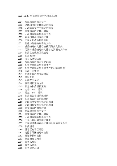
mcafee8.5i全部报警提示代码及意思:1024 发现感染病毒的文件1025 已成功清除文件感染的病毒1026 无法清除文件中感染的病毒1027 感染病毒的文件已删除1028 无法删除感染病毒的文件1029 要从扫描中排除的文件1030 无法从扫描中排除项目1031 拒绝访问感染病毒的文件1032 感染病毒的文件已被移到隔离文件夹1033 无法将感染病毒的文件移动到隔离文件夹1034 扫描已完成未发现病毒1035 扫描被取消1036 内存已感染病毒1037 发现感染病毒的引导记录1038 扫描发现感染病毒的文件1039 扫描发现感染病毒的文件并已清除病毒1040 活动日志错误1041 扫描报告内存分配错误1042 路径太长1043 介质有写保护1044 找不到指定的介质1045 指定的扫描项目无效1046 文件 I/O 错误1047 磁盘 I/O 错误1048 扫描报告常规系统错误1049 扫描报告内部系统错误1050 无法修复受密码保护的项目1051 无法扫描受密码保护的项目1052 感染病毒的捆绑对象1053 发现感染病毒的文件1054 感染病毒的文件已删除1055 无法删除感染病毒的文件1056 文件已移动到隔离文件夹1057 无法将感染病毒的文件移动到隔离文件夹1059 扫描超时1060 引导区病毒已清除1061 清除引导区病毒时出错1062 发送警报时出错1063 指定的选项无效1064 服务已启动1065 服务已结束1066 任务成功启动1067 无法启动计划的任务1068 计划的任务已停止1069 停止计划的任务时出错1070 任务成功完成1071 任务已取消1076 记录信息时出错1077 内存分配错误1086 扫描进程错误1087 按访问扫描已启动1088 按访问扫描已停止1089 扫描设置1090 OAS 已停止1091 已阻止脚本运行1092 已被行为阻挡规则阻挡1093 已被缓冲区溢出保护阻挡1094 已被端口阻挡规则阻挡1095 将被行为阻挡规则阻挡1099 将被缓冲区溢出保护阻挡1100 在文件中检测到宏1101 已从文件中删除宏1118 更新成功完成1119 更新失败:请参阅事件日志1120 正在更新1121 更新已取消1122 正在升级1123 升级失败,参阅事件日志1124 升级已取消1125 DAT 版本不够新1126 扫描任务被 DAT 文件的自动更新而取消1127 OAS 扫描引擎已禁用1128 扫描超时1129 扫描任务被 WINDOWS 关闭1200 进程已启动1201 进程已结束1202 按需扫描已启动1203 按需扫描完成1204 报告操作系统序列号1270 病毒已隔离,没有清除程序1271 病毒已隔离,启发式扫描1272 病毒已隔离,不能清除1273 病毒已隔离,已加密1274 病毒未清除或隔离1275 病毒,启发式扫描,隔离失败1276 病毒,清除错误,隔离失败1277 病毒,已加密,隔离失败1278 病毒,没有清除程序,已删除1279 病毒,启发式扫描,没有清除程序,已删除1280 病毒,清除错误,已删除1281 病毒,已加密,已删除1282 病毒,没有清除程序,删除失败1283 病毒,启发式扫描,删除失败1284 病毒,清除错误,删除失败1285 病毒,已加密,删除失败1286 病毒,没有清除程序,已继续1287 病毒,启发式扫描,已继续1288 病毒,清除错误,已继续1289 病毒,已加密,已继续1290 病毒,没有清除程序,拒绝访问1291 病毒,启发式扫描,拒绝访问1292 病毒,清除错误,已拒绝访问1293 病毒,隔离失败,已删除1294 病毒,隔离失败,删除失败1295 病毒,隔离失败,已继续1296 病毒,隔离失败,已拒绝访问1297 病毒,删除失败,已隔离1298 病毒,删除失败,隔离失败1299 病毒,删除失败,已继续1300 病毒,删除失败,已拒绝访问1401 用户检测1402 用户清除和移动失败1403 用户检测已移动1404 用户清除和删除失败1405 用户检测已删除1406 用户检测已移动1407 用户移动和删除失败1408 用户检测已删除1409 用户检测移动失败1410 用户检测已删除1411 用户删除和移动失败1412 用户检测已移动1413 用户检测删除失败1500 已清除电子邮件感染的病毒1501 感染病毒的电子邮件已隔离1502 无法清除邮件中感染的病毒1503 检测到感染病毒的电子邮件1504 感染病毒的邮件项目已删除1505 电子邮件内容已过滤1506 电子邮件内容已阻挡1507 入站邮件因磁盘空间不足而挂起1508 入站邮件已恢复1509 启动请求处理成功1510 关闭请求处理成功1511 警告 - 异常终止1512 出现最大负载的情况1513 邮件病毒已隔离和清除1514 邮件病毒已隔离[未清除]1700 服务已成功启动1701 服务已成功结束1702 文件已阻挡1703 发现感染病毒的邮件正文1704 邮件被主题行扫描阻挡1705 发现感染病毒的文件1712 出现内部错误1713 按需扫描已启动1714 按需扫描已完成1715 防病毒引擎已停止1716 防病毒引擎已启动1719 无更新可用1721 磁盘空间不足1722 发现感染病毒的文件1725 产品即将达到使用寿命1726 引擎即将达到使用寿命1727 产品已超过支持期限1728 引擎已超过支持期限1729 已超过产品使用寿命1730 已超过引擎使用寿命1800 任务已成功启动1801 启动任务时出错1802 任务已完成1803 停止任务时出错1804 已发现并清除文件病毒1805 感染病毒的文件已成功隔离1806 感染病毒的文件已删除1807 感染病毒的文件已忽略。
希尔希 迪吉追踪报警主机说明书

DIGI*TRACD T A001-0901DIGI*TRAC Annunciator Guide iiDTA001-0901, September, 2001Copyright © 2001 Hirsch Electronics Corporation. All rights reserved. S cramblePad ® is a registered mark of Hirsch Electronics Corporation. DIGI*TRAC™, MATCH™, S cramblePad, S crambleProx ® and SCRAMBLE*NET™ (abbreviated S*NET) are all trademarks of Hirsch Electronics Corporation.Hirsch Electronics Corporation1900 East Carnegie AvenueBuilding BSanta Ana, CA 92705-5520Phone:949-250-8888 or 888-809-8880Fax:949-250-7372Web:DTA001-0901Getting HelpIf you encounter a problem that is not discussed in this guide and youneed technical support, do the following:1.Contact your local dealer or the provider of this product.2.If your dealer is not available, contact Hirsch Technical Supportdirectly. This can be done in a number of ways:M a il il::Hirsch Electronics Corporation1900 East Carnegie AvenueBuilding BSanta Ana, CA 92705-5520Attn: Technical ServicesV o i c e:(877) HIRSCHX (technical queue)(888) 809-8880F a x:(949) 250-7362E m a il il: : :*****************************W W W:Whenever you call your local dealer or Hirsch, be sure to have yourregistration material, serial number and software version numberavailable.For future reference, record these numbers here.Serial Number: _________________________________Version Number: ________________________________Dealer: ________________________________________Dealer Phone #: ________________________________CCM Rev/Version #: _____________________________Getting Help iiiDIGI*TRAC Annunciator Guideiv Getting HelpDTA001-09011IntroductionThe DIGI*TRAC Annunciator (DTA) is used to monitor basic security functions—such as alarm, input, and relay status. It provides a local display of critical information near or outside the protected area.On the back of the Annunciator is an integrated MATCH2 board that communicates with the controller using the same digital channel as both the ScramblePad and MATCH.F i g u r e e 11: : D D IG I *T R A C C A A n n un unc c i a t o r r – – – S S i d e e V V i e wThe front of the Annunciator includes both a four-line, 20-character non-backlit LCD display and four status request buttons.The status request buttons are smart keys that change their meaning according to the current dialog displayed on the LCD screen abovethe keys.IntegratedMATCH-2DIGI*TRAC Annunciator User’s Guide 2Both a picture and an illustration of this front panel is shown in Figure 2:F i g u r e e 22: : D D IG I *T R A C C A A n n un unc c i a t o r r – – – F F r on ont t t V V i e wThese keys are used for status requests only and cannot issue commands of any sort.Status requests supported are:OAlarm Log Display from the Controller's Alarm Buffer (holds last 256 alarms)OCurrent Relay Status (to determine whether a door is locked)O Current Input Status (to determine where a door is closed or adevice is secured)This unit requires CCM 7.0 but does not require any host software for setup or operation. It is ideal for lobbies and other passages outside of the secured area where an individual can confirm that theprotected area is secure (such as locked and ready to leave).4-line LCD screen4-button keyboardDTA001-0901Installing the AnnunciatorThe DIGI*TRAC Annunciator comes pre-assembled with the MATCH2installed on the back of the DTA. There are several optional coverplates available as well as surface mount and flush mount backboxes.The DTA is a secure annunciator and requires a ScramblePad code orcard to activate the display.A simplified example of an Annunciator installation looks like Figure 3:F i g u r e e 33: : T T y p i c a l l A A n n u n c i a t o r r I I n s t a l l a t i o n3DIGI*TRAC Annunciator User’s Guide 4 A more complex example is shown in Figure 4:F i g u r e e 44: : A A n n un unc c i a t o r r E E x a m p l eThis example represents the way in which an annunciator can be used to monitor activity within a given area—in this case, three rooms incorporating readers, keypads, relays, motion detectors, amongst other devices—and supply alarm and event information specific to the entry and exit of personnel to/from that area.The required components include:ODIGI*TRAC Controller OAnnunciator O Keypad or Card ReaderMost of the installation and configuration requirements for theAnnunciator are identical to those you would observe for the MATCH2 board (refer to “MATCH Interface Installation” on page 7-74 in the DIGI*TRAC Design and Installation Guidefor more details).DTA001-09015T o install the Annunciator:1.Locate the place where you want to put the DTA. This should belocated near the ScramblePad/ScrambleProx and/or reader that will authorize the DTA’s use.e the selected surface mount plate or flush mount back box to position and draw an outline on the wall.3.Either secure the surface mount box to the wall or cut a hole for the flush mount box, then route the appropriate wires into the box.4.T urn off the power to the area or wall where you want to install the Annunciator.5.Depending on the type of device you are using, connect the device in one of these ways.If you are using a ScramblePad to activate the Annunciator :a.Route the wire from the Controller to the D*TRAC port on the DTA’s MATCH board as shown in Figure 5. Connect the wire to the port.F i g u r e e 55: : C C on onn n e c t t C C on ont t r o ll lle e r r a a n d d K K e y p a d d t t o o t t h e e A A n n u n c i a t o rThe DTA communicates with the MATCH2 via its RS-232 port (P2) and draws its power from one of the MATCH2's reader channels (C2). This comes pre-wired from the factory.Connecting a ScramblePad SCRAMBLEPAD Keypad Port D*TRAC PortDIGI*TRAC Controller Back of AnnunciatorDIGI*TRAC Annunciator User’s Guide 6 b.Connect an extension cable from the Keypad port on the DTA’s MATCH2 board.If you are connecting a reader to the Annunciator : a.Relocate the connector on Port 1 (P1) of the MATCH2 to Port2 (P2). This is only used as a power source for the DTA.b.Connect the Reader to Port 1 on the DTA’s MATCH2 board as shown in the example in Figure 6.F i g u r e e 66: : C C on onn n e c t i n g g R R e a d e r r t t o o t t h e e D D T AThis picture shows a specific type of proximity reader(CR20L) which is also used in the DS47L-SPX. Your reader and wiring specifications may differ from this picture.Connecting aReaderSOLDER &HEAT SHRINK ALL SPLICESCR20L-125-6005(HID# 6005)7If you are using a ScrambleProx as the keypad , follow these instructions (as shown in the example in Figure 7):a.Connect an extension cable from the Keypad port on the back of the ScrambleProx to the Keypad port on the DTA’s MATCH2 board.b.Relocate the connector on Port 1 of the MATCH2 to Port 2. This is only used as a power source for the DTA.c.Connect the DIGI*TRAC controller cable to the D*TRAC port on the DTA MATCH2 board.d.Disconnect the proximity reader connector from Port 1 on the ScrambleProx.e.If necessary, use an extension cable (Hirsch# MCRH) toconnect the loose reader cable from Port 1 on theScrambleProx to Port 1 on the MATCH2.Follow the connection chart shown in Figure 7.F i g u r e e 77: : C C on onn n e c t i n g g a a a S S c r a m b l e P r o x x t t o o a a a D D T AUsing aScrambleProxRoute keypad cable from theScrambleProx to the Keypad porton the DTA ➀from Port 1 on the ScrambleProx and connect it to Port 1 on the back of the DTA. If necessary , fabricate a cable for this purpose.6.If you are using a keypad, route the data wire from theScramblePad or ScrambleProx keypad to the Keypad port on theDTA’s MATCH2 board as shown in Figure 5.The ScramblePad or reader used to activate the DTA canalso be used as a standard entry access device. TheScrambleProx can be used as long as its integral readeris connected to the DTA’s Port 1 of the MA TCH2 instead ofPort 1 on the ScrambleProx as shipped from the factory.7.Follow the same power cable requirements as you would use toconnect an independent MATCH2. Ordinarily the controllerprovides sufficient power to operate attached ScramblePads andMATCH2 interfaces; however, there are conditions which requiremore power than the controller can supply.8.Secure the DTA to the box or plate.Once connected, the operator accesses the Annunciator by eitherentering a special code into the connected ScramblePad or using aspecial card on the attached reader or ScrambleProx. A simple menuappears on the Annunciator LED. The operator then follows the menuto access the information they require.8Assigning Annunciator PrivilegesThe process of enabling the DTA for the controller depends on thehost PC software used. There are three methods for assigningAnnunciator privileges to a user:O Keypad assignmentO SAM assignmentO Velocity assignmentEach of these methods is discussed in this section.Keypad AssignmentT o assign Annunciator privileges from a ScramblePad:1.From an attached ScramblePad, enter program mode.e the following command and syntax to assign Annunciatorprivileges to a user:44*1*User Number*Codewhere User Number is the number assigned to this user and theCode is the PIN number assigned to this user at this door toactivate the DTA.You can also use this command to assign Annunciator privilegesthrough the SAM diagnostics window or the MOMENTUM Hirsch T estT ool.SAM AssignmentT o assign Annunciator privileges using SAM:1.Access the Add/Edit User Group worksheet by selecting A A ddup in the Groups menu, or press F F3 3 A A d d.G r o up2.Select the User Group you want to enable for this function. TheAdd/Edit User Group dialog box appears.3.Either define a new group or select an existing user group.4.Click the “Function” field arrow. An option list appears.m C C onont t r o l button. A list of available alarm functions5.Select the A A l a r mappears.m C C a n c e l function.6.Select the A A l a r m9107.Select the access zone and the code extension you require to activate this DTA.F i g u r e e 88: : P P r o g r a mm mmi i n g g t t h e e C C o n t r o l l e r r U U s i n g g S S AM Select Alarm Cancel fromSelect the AccessZone you need forthis function Select the ID Form at and Code extension you want to activate the DTAthe Alarm Control optionlistVelocity AssignmentIf you are using Velocity, you can assign an operator the ability to usethe Annunciator in one of two ways:O Define a Function GroupO Define a user credential through Enrollment ManagerCreating a Function Group is the best way if you plan to assignAnnunciator privileges to more than one user.Function Group AssignmentT o assign Annunciator privileges for a group through Function Groups:1.From the Velocity system tree, select the Function Groups file. Alist of all currently-defined function groups and the Add NewFunction Group button appear in the right hand Componentspane.on G G r ououp p button to createdd N N e w w F F ununc c t i on2.Either double click the A A dda new function group, or double click an existing function group.The Function Group Properties dialog box appears.3.If this is a new function group, enter a new function group namein the Name field. If this is an existing function group, a namealready appears.dd.... button to add the required code extension to this4.Click the A A ddfunction group. The Define Extension dialog box appears.5.In the “Extension Digits” field, enter one or two digits.6.In the “Function Category” field, select A A l a r m from the pull-downoption list.m C C a n c e l from the pull-down7.From the “Function” field, select A A l a r moption list.8.From the “Controller” combo box, select the currently-definedcontroller to which this extension code applies.9.From the “Control Zone” combo box, select the currently-definedcontrol zone or master control zone during which this extensiondigit applies.dd to register the new extension digit in the lower window.10.Click A A dd11.Click O O K to return to the Function Group Properties dialog box.12.Click O O K to return to the main menu.11ing Function Groups in the Administrative Mode, assign thisfunction group to the specified user(s) on the Function property page.F i g u r e e 99: : A A s s i g n i n g g A A n nu nun n c i a t o r r P P r i v i l e g e s s u u s i n g g V V e l o c i t y ’s s F F u n c t i o n nG G r o up Click A A dd dd....Select A A l a r m &A l a r m m C C a n c e lClick O O KClick A A dd dd....Single Credential AssignmentT o assign Annunciator privileges for a single credential through Enrollment Manager:1.Open the Enrollment Manager.2.Select the person to whom Annunciator privileges should beassigned.dd N N e w3.Create a new credential by double clicking the A A ddC r e d e n t i a l button. The Credential Properties dialog box for theselected person appears.4.Fill out this form as required making sure to supply a code orcard.5.Click the Function tab.unc c t i o n radio button.6.If not already selected, click the S S i n g l e e F F un7.In the “Function Category” field, select A A l a r m from the pull-downoption list.m C C a n c e l from the pull-down 8.From the “Function” field, select A A l a r moption list.9.From the “Controller” combo box, select the currently-definedcontroller to which this extension code applies.10.From the “Control Zone” combo box, select the currently-definedcontrol zone or master control zone during which this extension digit applies.dd to register the new extension digit in the lower window.11.Click A A dd12.Click O O K to return to the Enrollment Manager main menu. Thenew credential appears in the Credential pane for the selected user.13.Click O O K to return to the main menu.1314F i g u r e e 110: : A A s s i g n i n g g A A n nu nun n c i a t o r r P P r i v i l e g e s s t t o o a a a C C r e d e n t i a l l u u s i n g g E E n r o l l m e n t t M M a n ag age er Click Function T abthen A A l a r m &A l a r m m C C a n c e lEnter code and/orcard15Operating the AnnunciatorThe following procedure shows you how to use the Annunciator.1.Go to the keypad (either ScramblePad or ScrambleProx) or cardreader connected to the DTA. This normally will be the keypad or reader mounted closest to the DTA.Whenever the DTA is not activated, it displays the time and day like this example:F i g u r e e 111: : I I n a c t i v a t e d d D D T A A S S c r ee een n2.Perform one of these procedures:•At the keypad, enter your special DTA-activation code. This is often a code extension (SAM) or function group (Velocity).•At a reader, swipe your special DTA-activation card.Your regular access code/card alone cannot activate the DTA. The code/card must be used with an extension digit or function group digits. The system administrator must issue you this special code/card or extension to activate the DTA.The DTA is activated. The DTA’s screen displays the initial screen like Figure 12.F i g u r e e 112: : A A n n un unc c i a t o r r M M a i n n M M e nuEND ALMLOG INP STAT RELAYSTAT16These options are:3.Press the button for the option you want.A list of the current alarms or status points (input or relay) for the connected controller appear.You will only see the alarms or status for the controllerconnected to this DTA. No other controller’s status is displayed.O If you press the ALM LOG button, a screen like Figure 13 appears:F i g u r e e 113: : A A l a r m m L L o g g M M e n uOnly one alarm at a time can be displayed.P r e s s s t t h i s b s button to utton to utton to::ENDEnd the current session and return the DTA to inactive mode.ALM LOGDisplay the log of all alarms experienced by this controller only.INP STATDisplay the current status for all inputs connected to this controller only.RELAY STATDisplay the current status for all relays(outputs) connected to this controller only.BACK FWD SAVEERASEO If you press INP STAT, a screen like Figure 14 appears:F i g u r e e 114: : I I n p u t t S S t a t u s s M M e nuThis screen displays the current Alarm Input or ExpansionAlarm Input status. The report is time stamped at the time thebutton is pushed. A list of abbreviations you will find on thisscreen are shown in the following table:A line fault of some sort, followed by a briefexplanation; in the preceding case, it indicates anopen circuit (‘open ckt’).* Designates an input or expansion input iscurrently in alarm (even if masked).AL Alarmunmasked.iscontactsecure... AlarmisContactisactive.RQ RQEcontactactive.contactTP T amperisM Masked by one of the following devices:Tz MaskedbyZone.TimeZone.byControlC MaskedUnlock.Ul Maskedbytimer.DelaybyEntry/ExitX Masked1718An example of several possible input status values are shown in Figure 15:F i g u r e e 115: : I I n p u t t S S t a t u s s E E x a m p l eO If you press RELAY STAT, a screen like Figure 16 appears:F i g u r e e 116: : R R e l a y y S S t a t u s s M M e nuA list of abbreviations used in this display are explained in the following table:R The relay designation followed by the number of this relay, such as R1 or R2.* Relay isenergized. The following abbreviations specify the current condition ofthe relay:D (on left) Door access in progress.U Unlock/Relock.C Control timer.N Control Force On.BACK FWD EXIT19An example of this screen appears in Figure 17:F i g u r e e 117: : R R e l a y y S S t a t u s s E E x a m p l eIn almost every case, the list of alarms, inputs, and/or outputs is longer than four lines.4.Press one of these keys:•Use the FWD key to move forward in the list.•Press the BACK key to move backward in the list.•Press the EXIT key to return to the main menu shown in Figure 12.F in 2nd group Control Force Off.A Actuate by Time Zone. D (in middle)Disable by Time Zone. ZControl Zone “Drive On” by Alarm Input or Expansion Alarm Input. F in 4th group Control Zone “Drive Off” by Alarm Inputor Expansion Alarm Input.L Lock Down.O Lock Open.. (period)Particular function is not currently active.•If this is Alarm Log, use the ERASE key to delete the alarmlog. All alarms are cleared from the buffer and a screen likethis appears.•If this is the Alarm Log, press SAVE to save the current alarmentries for later review.5.When you’re finished looking through a particular list, press theEXIT key to return to the main menu. Press the END key todeactivate the DTA.20Appendix: Wiring SpecificationsFor information on basic electrical wiring specifications, such as wiretypes and lengths used for connecting the DTA, refer to“ScramblePad/MATCH Inputs” on page 2-15 of the DIGI*TRACDesign and Installation Guide (Hirsch# MAN001).For information on powering a ScramblePad or MATCH locally, see“Powering ScramblePads/MATCH Interfaces Locally” on page 2-31 inthe DIGI*TRAC Design and Installation Guide.For additional information, refer to “Powering the ScramblePadLocally” on page 7-71 in the DIGI*TRAC Design and InstallationGuide for the best technique to use.2122。
MDEC故障代码

359
OPEN LOAD CYL.B9
360 OPEN LOAD CYL.B10
361 POWER STAGE FAIL 1
362 POWER STAGE FAIL 2
363 STOP POWER STAGE 1
364 STOP POWER STAGE 2
365
OPEN LOAD CYL.B8
366
0 29 0 30 0 31 0 32 0 33 0 34 0 35 0 36 0 37 0 38 0 39 0 40 0 41 0 42 0 43 0 44 0 45 0 46 0 47 0 48 0 49 0 50 0 51 0 52 0 53 0 54 0 55 0 56 0 57 0 58 0 59 0 60 0 61 0 62 0 63 0 64 0 65 0 66 0 67 0 68 0 69 0 70 0 71 0 72 0 73 0 74 0 75
351
OPEN LOAD CYL.B1
352
OPEN LOAD CYL.B2
353
OPEN LOAD CYL.B3
354
OPEN LOAD CYL.B4
355
OPEN LOAD CYL.B5
356
OPEN LOAD CYL.B6
357
OPEN LOAD CYL.B7
358
OPEN LOAD CYL.B8
190
未使用
191
未使用
192
未使用
193
未使用
194
未使用
195
未使用
196
未使用
197
未使用
198
未使用
199
未使用
ThinkPad错误码对照表及解决方法

110
平面奇偶
检测内存
内存插槽
如果有接到电脑的扩展部件移除
系统主板
111
IO奇偶
检测内存
扩展部件或端口复制器
系统主板.
11XX
1101 A类设备检测失败
串口设备
通讯接线
系统主板
12XX
1201 B类检测失败
系统主板 (红外)
恢复系统设置到进入休眠之前的状态
如果内存容量更换了,重新制作休眠文件(删除c下面的休眠文件再进入)
Fan error:风扇错误
风扇
Thermal sensing error:热感应错误
系统主板�
安全芯片
系统主板
0197
非法的远程修改要求
远程配置安全保安芯片失败. 确认该操作重试.
01C8
多个Modem设备 - 移走其中一个按Esc继续.
移走一个MiniPCI Modem 卡或Modem子卡, 或者按Esc忽略该错误继续.
系统主板
01C9
多个网络类设备 - 移走其中一个按Esc继续.
输入SuperVisor(超级)密码进入BIOS 设置工具, 选择Config, 选择 IBM Security Chip, 选择Clear IBM Security Chip 可清除这个错误
安全芯片
系统主板
0196
安全保安硬件被移除
输入SuperVisor(超级)密码进入BIOS 设置工具, 选择Config, 选择 IBM Security Chip, 选择Clear IBM Security Chip 可清除这个错误
移除miniPCI网卡.
- 1、下载文档前请自行甄别文档内容的完整性,平台不提供额外的编辑、内容补充、找答案等附加服务。
- 2、"仅部分预览"的文档,不可在线预览部分如存在完整性等问题,可反馈申请退款(可完整预览的文档不适用该条件!)。
- 3、如文档侵犯您的权益,请联系客服反馈,我们会尽快为您处理(人工客服工作时间:9:00-18:30)。
bÌ +Úxì¿÷0~ür|}Ì 4Í « R ü. /4 t ±¯ {o i #h¡ k ³ 4{¡ ¡¢£¤¥ y4+ ë¯ë¦§ë|}먩Ì
=>67
(?)* * @0220A08* BC* D1/* EFG* D1/*HIG* ;* JKL=:M1N5OP 1=QL<41:=* A149* OLN1. RST UVWXYZ[\] ^_`abcde fg hijklm nopqrstu ª H«v@2pmPwe^U1sPHCP !%##CP +x!y3z!.z&{ (!)* |lqTo* }~G Eb4R* HG* HRub^* }EG* ;* @RXUS404pRu0W* 0u0W]^p^* prbu4p. oS/dm* drkmRM1sS* 4]Uk* ++* d* d* sk.k/kstm4* lnS4t* stU1sl4Rs]* K1tlt*Ul4oRtm ¬ H«;*H*@c1m*}1nsR61RcG*!"?"G*,& $3zz#.zz$;* ($)*** ®¯4°±²4³´µ4;* / # 0 $ 4¶ i ?" · ¬ H«;* ü¹!"#º»4!%%'4!, #3$.' op#Ñ:¸z (,)* @9/1kckA1n*G*kuckj*HG*~[ac1*G* ;*wk^U1j[4ij8*r1^k[^k*n[a^. ¬ H«;* H* kr* 68* [* ^Ukn1k^* !* [rkuiM1ja^* 1u* [* X1c14[j8* n[XU* 1u* ajk8 }kr*1jRqG*!%%+G* !3!$!.!$; (+)P h0A0^01P IGP FR^R80P }GP h0408R^P }GP ;P @Rjjq041RmP 64AmP ^ja/P 1m4jqa1mP 'P 0mKP @.j0<41MP UjR41mP <Rm<m4j041Rm^P 1mP U0. ¬ H«;P ~trpd4NP uk<4P pTP HGP Ap4oP drtuiMpNdcP NtTUpNd4iN]P puQtn4piu !%%!GP!? +3$%.$,; (')P #$% 4 ¼ 954 ½¾ Ý4 ;P $z h / # 0 $ 4¿À4¶ i?">-st«op#:uvij ¬ H«;P ü¹op# :º»4!%%+4!' ,3$%.$%&; ()P -É.4Á¡Â4{¯4;P Ã@/#0?" ++ hstij ¬ H«;P üÝÃ@¶í7:4!%%&4?+ +3,',.,'+; ¬ }«;P Í3Í8: Î (&)P ÄÅÆ4ÇÈÉ4ÊËÌ;P @8?"#: ϱÐÑ4!%%$Ò?,$.?+? @ !%?!.%,.%?P Ó !%?!.%.?P Ôc @ ÕÖ×Ø ÙÚÛ EÜ×Ý Þßàc
!"#$%
& ' ( ) *
)+
!"#$%& '() *"+,- .,/0 12- 3,4 5- 6789:;9< 1=> 1?5@
R(&S 89:%7//,)() (" T("U(;"K V<KS:9 N:&,",J,:) W7K(," XT("U(;"KY0 8*394: Z$"$9;/ [;&;> %/("(%;/ %S;9;%&$9()&(%)> &9$;&J$"& ;"[ ,:&L %,J$ ,+ 5E@ \;&(7"&) R(&S 89:%7//,)() S,)\(&;/(]7^ (" &S7 6(9)& N##(/(;&7^ _,)\(&;/ ,+ T("U(;"K `7^(%;/ V"(a79)(&< +9,J b;"4 1??E &, M7\&4 1?51 R797 ;";/<]7^ 97&9,)\7%&(a7/<4 ;*/7)3/ OS7 \97a;/7"%7 ,+ 89:%7//,)() R;) S(KS79 (" &S7 \,\:/;&(," R(&S %79&;(" ,%%:\;&(,") (" T("U(;"K4 P9:%7//,)() ,%%:997^ J;("/< +9,J N\9(/ &, N:K:)& 7;%S <7;9- ;"^ &S7 ":J879 ,+ \;&(7"&) R(&S 89:%7//,)() S;^ 877" K9,R("K (" 97%7"& <7;9)4 OS7 J;(" %/("(%;/ J;"(+7)&;&(," R;) +7a79- ;%%,J\;"(7^ 8< )R7;&("K- J:)%/7 ;"^ U,("& \;("- S7\;&,)\/7",J7K;/< ;"^ ), ,"RS(/7 cPd- _ZP ;"^ efO ^$%9$;)$^ (" ^$++$9$"& ^$K9$$) ;"^ ;8",9J;/ /;%&;&$ ^$S<^9,K$";)$ R;) +,:"^ (" ),J$ \;&($"&)4 OS$ %,J8(D ";&(," ,+ 9(+;J\(%(" ;"^ ^,g<%<%/("$h ,9 9(+;J\(" ;"^ /$a,+/,g;%(" ;%S($a$^ ; S(KS (J\9,a$J$"& 9;&$ XFF451QY4 +4-.)7/,4-/ OS$ \9$i a;/$"%$ ,+ 89:%$//,)() () S(KS (" T("U(;"K- ), 89:%$//,)() )S,:/[ 8$ %,")([$9$[ RS$" &S$ \;&($"& \9$)$"&) R(&S \9(J;9< %,J\/;("& ,+ +$a$9 ,+ :"j",R" ,9(K("4 OS$ ("%(^$"%$ ,+ 89:%$//,)() () ("%9$;)("K (" dS(";- RS(%S )S,:/^ 8$ \;(^ J:%S J,9$ ;&&$"&(,"4 <=*0 >46:/? 89:%$//,)()I +$a$9I ^()$;)$ ;&&9(8:&$)
,-./#01,.2/3456789! "#:;<=>:?@ 52? ABCDE;<A5BF GH BIJ;<KLMNOPQRSTURVWXURY Z[\]OPQ^_`OPQabQA1BF cdef g^7hg5ijkl:,-./#9mnEo& pq5rs A@BF ,-./#tuIJvwxy+k zRq{R|}~R^a ACDEBF wH 1??E & 5 ' 1?51 & F 'P5 5E@ ,-./ #9m5|<F ! !"#$%
!"#$%&'& () *+, -./'0"/& 1'/2 34560$$&'& '" 7'"8'."9 :%9254 ;5/("(<(5& =09'("
SO3 T$PU:"> VW(XYW(X&(XW(X/( DZEZJ[\> EW,P<(P](WPY: OEOEO[T^J* _:X$9X`(X<W OEZaZT^bcdVd- ed_ f(W,X+$"g> JZ f(W,X`,> hGO_H b:$X](" a$iW9&Y$"& ,+ ["+$j&(,:) a()$;)$)> Kk$ 6(9)& O++(/(;&$l G,)i(&;/ ,+ m("U(;"g V$l(j;/ Z"(n$9)(&<> Z9:Yo(> m("U(;"g =@??AC> Fk("; \F,99$)i,"l("g ;:&k,9> pPY;(/q Y;Y;&;/(:8:/r<;k,,4%,Y4%" >;3&/4.6/? @3806/'A0 K, ("n$)&(g;&$ $i(l$Y(,/,g<> %/("(%;/ %k;9;%&$9()&(%)> /;8,9;&,9< +("l("g)> &9$;&Y$"& ;"l ,:&%,Y$ ,+ i;&($"&)