viking pump备件手册
丹佛斯变量容积泵系列20、20-27系列零件手册说明书
MAKING MODERN LIVING POSSIBLEQuick Reference Parts ManualVariable Displacement Pump Series 20, 20-27 seriesAX00000099 en-US | 520L0910 • Rev 0203 • August23AX00000099 en-US | 520L0910• Rev 0203 • August Contents Exploded view drawing (20 thru 23 series) (4)Service parts (20 thru 23 series) (5)Exploded view drawing (24 thru 27 series) (6)Service parts (24 thru 27 series) (7)SPV2/033 (20 series) (8)SPV2/052 (21 series) (8)SPV2/070 (22 series) (8)SPV2/089 (23 series) (8)SPV2/119 (24 series) (9)SPV2/166 (25 series) (9)SPV2/227 (26 series) (9)SPV2/334 (27 series) (9)Service parts Drive shafts4AX00000099 en-US | 520L0910 • Rev 0203 • August5AX00000099 en-US | 520L0910• Rev 0203 • August Item # Discription SPV2/033 (20) SPV2/052 (21) SPV2/070 (22) SPV2/089 (23) Overhaul seal kit 9510224 9510227 9510230 9510233 1 Shaft seal kit 050088 050088 050088 0503022 O-ring 056788 (9004104-2340) 056788 (9004104-2340) 056788 (9004104-2340) 071860 (9004104-2380)3 O-ring 008821 (9004104-1290) 008821 (9004104-1290) 008821 (9004104-1290) 008979 (9004104-1360)4 Seal kit 9510022 9510022 9510022 95100215 Front bearing kit 050575 (9510251) 050575 (9510251) 050625 (9510256) 050658 (9510259)6 Swashplate, 18° 002725 9210279 9220570 95107617 Cylinder block kit 510149 593251 596890 92309738 Piston kit, set of 3 711291 (not a kit of 3) 9510408-0010 9510408-0001 9510408-0002 8 Remanufactured 711291 R9510408-0010 R9510408-0001 R9510408-00029 Slipper retainer 9200158 003210 (9210292) 003707 (9220628) 004176 (9230234) 10 Slipper ret. guide J9200124 003160 (9210219) 9220500 9230158 11 Pilot ring 002709 010678 013862 00432512 Bearing plate 002733 585885 585893 56167013 Valve plate, cw 002881 003368 003889 004333Valve plate, ccw 002899 003376 003897 00434114 Rear bearing kit 050567 (9510250) 050591 (9510253) 050617 (9510255) 050641 (9510258) 15 End cap gasket 9200088 9210204 9220425 9231081 16 Chg pump gasket, gear 9801235 9801235 9801235 9801235 gerotor with IPOR n/a 9803241* 9803241* 9803241* gerotor without IPOR n/a 9803252* 9803252* 9803252*17 O-ring 000869 (9004100-1390) 000869 (9004100-1390) 512007 (9004100-1430) 512007 (9004100-1430) 18 O-ring 000851 (9004100-1360) 000851 (9004100-1360) 512008 (9004100-1410) 512008 (9004100-1410) 19 Thrust plate 010520 003228 (9210293) 003699 (9220626) 00418420 Trunnion bearing kit 050583 (9510252) 050609 (9510254) 050633 (9510257) 050666 (9510639) prior to 88-01-xxxxx 951026021 O-ring 000927 (9004100-2260) 000935 (9004100-2280) 000943 (9004100-2300) 000950 (9004100-2320) 22 Trunnion shim kit 9510422-0001 9510422-0002 9510422-0003 9510422-0004 23 Servo piston link 589317 589317 589325 59467187-13 thru 97-23 n/a 9210620 9221367 9230787 24 Retaining ring 9006300-0050 9006300-0050 9006300-0062 9006300-006225 Pin 013904 (9004830-0001) 013904 (9004830-0001) 013680 (9004830-0002) 013680 (9004830-0002) 26 Check valve assembly 075366 (9800648) 075366 (9800648) 075366 (9800648) 075366 (9800648) 27 O-ring 056770 (9004101-0150) 056770 (9004101-0150) 056770 (9004101-0150) 056770 (9004101-0150) 28 Servo sleeve assembly 9200582 9200582 9510207 9510207 29 Servo sleeve assembly 9200583 9200583 9510350 9510350 30 Stroke limiter kit 9200515 9200515 9221078 9221078 31 Torx screw 9007276-0011 9007276-0011 9007276-0011 9007276-0011 32 Servo retainer 9200087 9200087 9220419 9220419 33 Control gasket 9803340 9803340 9803340 980334034 O-ring 001032 (9004101-0140) 001032 (9004101-0140) 001032 (9004101-0140) 001032 (9004101-0140) 35 Front cover gasket 9200076 9210201 9221528 9230124 36 Cylinder block 049155 049163 014878 01491036 Remanufactured n/a R9210576 R9221102 R9230651 37 Cylinder block assy n/a n/a 11077853 520087/P * Indicated special charge pump gaskets (item # 16) are not included in the overhaul seal kit.Service parts6AX00000099 en-US | 520L0910 • Rev 0203 • August7AX00000099 en-US | 520L0910• Rev 0203 • August Service parts Item # Discription SPV2/119 (24) SPV2/166 (25) SPV2/227 (26) SPV2/334 (27) Overhaul seal kit 9510236 9510239 9510316 9510242 1 Shaft seal kit 050302 050302 058537 0505342 O-ring 000984 (9004100-2380) 000984 (9004100-2380) 049718 (9004100-2420) 000992 (9004100-2430)3 O-ring 008979 (9004104-1360) 008979 (9004104-1360) 680892 (9004104-1440) 012187 (9004104-1490)4 Seal kit 9510021 9510021 n/a n/a5 Front bearing kit 050658 (9510259) 9510264 9510267 050732 (9510270)6 Swshplate, 18° 9240197 9250164 9260152 9270462 7 Cylinder block kit 9240641 634923 9260369 9270658 8 Piston kit, set of 3 9510408-0004 9510408-0005 9510408-0006 9510408-0009 8 Remanufactured R9510408-0004 R9510408-0005 R9510408-0006 R9510408-0009 9 Slipper retainer 9240125 9250170 9260072 9270486 10 Slipper ret. guide 9240097 005090 046243 00558711 Pilot ring 702381 634907 634915 63489912 Bearing plate 9240560 585901 9260321 58592713 Valve plate, cw 004895 651810 9260355 62232413 Valve plate, ccw 004903 628933 9260356 65196814 Rear bearing kit 050674 (9510261) 050690 (9510263) 055434 (9510266) 050724 (9510386) 15 End cap gasket 9240549 9250587 9260144 9270710 16 Chg pump gasket, gear 9801604 9801604 9801604 9801604 gerotor with IPOR 9803241* n/a n/a n/agerotor without IPOR 9803252* n/a n/a n/a17 O-ring 000901 (9004100-1510) 000901 (9004100-1510) 000919 (9004100-1560) 000919 (9004100-1560) 18 O-ring 000893 (9004100-1500) 000893 (9004100-1500) 000992 (9004100-2430) 000992 (9004100-2430) 19 Thrust plate 011015 (9240124) 005181 (9250171) 049635 (9260073) 004184 (9230235) 20 Trunnion bearing kit 050682 (9510262) 050609 (9510254) 050633 (9510257) 050666 (9510639) 21 O-ring 000968 (9004100-2340) (9004100-2280) (9004100-2300) 000950 (9004100-2320) 22 Trunnion shim kit 9510422-0005 9510422-0006 9510422-0007 9510422-0008 23 Servo piston link 9240584 9250617 9260252 9270653 24 Retaining ring 9006300-0075 9006300-0075 9006300-0087 9006300-008725 Pin 9004830-0008 9004830-0008 013680 (9004830-0002) 013680 (9004830-0002) 26 Check valve assembly 075366 (9800648) 543553 (9802028) 543553 (9802028) 543553 (9802028) 20 gpm 527887 n/a n/a n/a27 O-ring 056770 (9004101-0150) 063230 (9004101-0270) 063230 (9004101-0270) 063230 (9004101-0270) 20 gpm valve 012575 (9004105-1170) n/a n/a n/a28 Servo sleeve assembly 9510208 9510208 n/a n/a29 Servo sleeve assembly 9510351 9510351 9510331 9510331 30 Stroke limiter kit 9240326 9240326 9260185 9260185 31 Torx screw 9007276-0011 9007276-0011 9007276-0011 9007276-0011 32 Servo retainer 9240076 9240076 9270178 9270178 33 Control gasket 9803340 9803340 9803340 980334034 O-ring 001032 (9004101-0140) 001032 (9004101-0140) 001032 (9004101-0140) 001032 (9004101-0140) 35 Front cover gasket 9240070 9250158 9260145 9270175 17 Cylinder block 049171 073585 073619 07118317 Remanufactured R9240394 R9250470 R9260231 R9270495 * Indicated special charge pump gaskets (item # 16) are not included in the overhaul seal kit.8AX00000099 en-US | 520L0910 • Rev 0203 • AugustPart Number Description010827 14 tooth spline, gear charge pump707828 20 tooth spline, gear charge pump046557 21 tooth spline, M10 threaded hole, gear charge pump708073 Straight key, 3/8-24 UNF-2B threaded hole, gear charge pump 9003261-3132 Key, 5/16 x 5/16 x 2 1/2080465 14 tooth spline, gear charge pump9210663 14 tooth spline, gerotor charge pump018812 21 tooth spline, gear charge pump9210673 21 tooth spline, gerotor charge pump9210428 Tapered, gear charge pump9003310-3724 Key5000606 (9700169) Slotted nut9210538 Straight key, gear charge pump9003261-3132 Key, 5/16 x5/16 x 2 1/2144402 14 tooth spline, gear charge pump9221447 14 tooth spline, gerotor charge pump079913 (9220515) 19 tooth spline, gear charge pump9220527 20 tooth spline, 3/8-24 UNF-2B threaded hole, gear charge pump 9221475 20 tooth spline, 3/8-24 UNF-2B threaded hole, gerotor charge pump 048504 (9220417) 21 tooth spline, gear charge pump9221441 21 tooth spline, gerotor charge pump046581 (9220884) Tapered, gear charge pump9003310-3724 Key5000606 (9700169) Slotted nut039644 (9221065) Straight key, 3/8-24 UNF-2B threaded hole, gear charge pump 9003261-3132 Key, 5/16 x5/16 x 2 1/29230476 14 tooth spline, gear charge pump9230951 14 tooth spline, gerotor charge pump014985 (9230325) 21 tooth spline, gear charge pump9230968 21 tooth spline, gerotor charge pump9230173 23 tooth spline, 3/8-24 UNF-2B threaded hole, gear charge pump 9231014 23 tooth spline, 3/8-24 UNF-2B threaded hole, gerotor charge pump 9230147 27 tooth spline, 3/8-24 UNF-2B threaded hole, gear charge pump 9230445 Tapered, 1.5” nominal shaft dia., gear charge pump9003310-3724 Key5000606 (9700169) Slotted nut9230989 Tapered, 1.375” nominal shaft dia., gerotor charge pump 9003310-3724 Key5000606 (9700169) Slotted nut9230626 Straight key, 3/8-24 UNF-2B threaded hole, gear charge pump 9003261-3132 Key, 3/8 x 3/8 x 2 1/2SPV2/033 (20 series)SPV2/052 (21 series)SPV2/089 (23 series)SPV2/070 (22 series)9AX00000099 en-US | 520L0910• Rev 0203 • August Drive shaft Part Number Description 07930113 tooth spline, M14 x 2-6H tapped hole, gear charge pump 924068513 tooth spline, gerotor charge pump 04684727 tooth spline, M14 x 2-6H tapped hole, gear charge pump 9240231Tapered, gear charge pump 9003326-0005Key 9700189Slotted nut 9240713Tapered, gerotor charge pump 9003326-0005Key 9700189Slotted nut 039982Straight key, 1/2-20 UNF-2B threaded hole, gear charge pump 9003261-3732Key, 3/8 x 3/8 x 2 1/2054940 13 tooth spline, gear charge pump047894 27 tooth spline with M14 x 2-6H tapped hole, gear charge pump9250409 Straight key, 1/2-20 UNF-2B threaded hole, gear charge pump9003261-3732 Key, 3/8 x 3/8 x 2 1/29260140 13 tooth spline, gear charge pump045930 27 tooth spline, M14 x 2-6H tapped hole, gear charge pump9260176 Straight key, 1/2-20 UNF-2B threaded hole, gear charge pump9003261-5040 Key, 1/2 x 1/2 x 3 1/2077727 15 tooth spline, gear charge pump9270741 40 tooth spline, M16 tapped hole, gear charge pump561530 Straight key, 1/2-20 UNF-2B threaded hole, gear charge pump 9003261-6244 Key, 5/8 x 5/8 x 4SPV2/166 (25 series)SPV2/119 (24 series)SPV2/334 (27 series)SPV2/227 (26 series)AX00000099 en-US | 520L0910 • Rev 0203 • August1011AX00000099 en-US | 520L0910• Rev 0203 • August NotesDanfoss Power Solutions is a global manufacturer and supplier of high-quality hydraulic and electronic components. We specialize in providing state-of-the-art technology and solutions that excel in the harsh operating conditions of the mobile off-highway market. Building on our extensive applications expertise, we work closely with our customers to ensure exceptional performance for a broad range of off-highway vehicles. We help OEMs around the world speed up system development, reduce costs and bring vehicles to market faster. Danfoss – Your Strongest Partner in Mobile Hydraulics.Go to for further product information.Wherever off-highway vehicles are at work, so is Danfoss. We offer expert worldwide support for our customers, ensuring the best possible solutions for outstanding performance. And with an extensive network of Global Service Partners, we also provide comprehensive global service for all of our components. Please contact the Danfoss Power Solution representative nearest you.Products we offer:y Bent Axis Motorsy Closed Circuit Axial Piston Pumps and Motorsy Displaysy Electrohydraulic Power Steeringy Electrohydraulicsy Hydraulic Power Steeringy Integrated Systemsy Joysticks and Control Handlesy Microcontrollers and Softwarey Open Circuit Axial Piston Pumpsy Orbital Motorsy PLUS+1® GUIDEy Proportional Valvesy Sensorsy Steeringy Transit Mixer Drives Comatrol Schwarzmüller-Inverter www.schwarzmueller- Turolla Valmova Hydro-Gear Daikin-Sauer-Danfoss Local address:Danfoss can accept no responsibility for possible errors in catalogues, brochures and other printed material. Danfoss reserves the right to alter its products without notice. This also applies to products already on order provided that such alterations can be made without subsequential changes being necessary in specifications already agreed.All trademarks in this material are property of the respective companies. Danfoss and the Danfoss logotype are trademarks of Danfoss A/S. All rights reserved.Danfoss Power Solutions 22F, Block C, Yishan Rd Shanghai 200233, China Phone: +86 21 3418 5200Danfoss Power Solutions GmbH & Co. OHG Krokamp 35D-24539 Neumünster, Germany Phone: +49 4321 871 0Danfoss Power Solutions ApS Nordborgvej 81DK-6430 Nordborg, Denmark Phone: +45 7488 2222Danfoss Power Solutions US Company 2800 East 13th Street Ames, IA 50010, USA Phone: +1 515 239 6000AX00000099 en-US | 520L0910 • Rev 0203 • August © Danfoss A/S, 2015。
技术服务手册-VikingPump

图 1 – 图 GG、HJ 和 HL4197 系列 采用法兰端口的支座型手泵图 2 – 图 AS、AK 和 AL4197 系列 采用法兰端口的支座型手泵吸液口图 3特殊机械密封:维修这些泵时应格外小心。
请务必阅读并遵照随泵提供的所有特殊说明。
系列泵设计合理,可在各种条件下长时间、无故障地工作,而且只需很少的维护。
以下要点有助于确保泵能长时间正常工作。
让泵尽可能保持干净,这样做便于开展检查、调整和维修工作,以免遗漏脏污的黄油嘴。
如果泵要存放六个月或更长时间(或这么长时间不使用泵),则必须排干泵中的液体,然后在所有内部零件上涂抹薄薄的一层非去污型 .SAE .30 .号油。
润滑各接头,在泵轴延伸部分涂上润滑脂。
Viking .建议您每隔轴拨转一周,以便使油扩散开来。
建议维修工具:为了确保正确维修 4197系列泵,必须使用以下工具。
这些工具是对标准机修工具(如:开口扳手、钳子和螺丝刀等)的补充,大多数都可以从工业用品店购得。
内六角扳手(定位螺丝和特殊机械密封).– .Viking .P/N . -810-047-999 .GG-HJ-HL .4197 ..– .Viking .P/N . -810-0 9-375 .GG-HJ-HL .4197机械密封安装套筒.0 75 .英寸密封的 . -751-001-730.1 5 .英寸密封的 . -810-004-730轴承锁紧螺母活动扳手 .– . -810-043-375可调销式活动扳手,用于轴承套端盖机械密封泵体滚珠轴承空转销溢流阀图 4– GG、HJ 或 HL 4197 型号剖视图图 5 – GG、HJ 和 HL 4197 型号部件分解图编号零件名称编号零件名称编号零件名称锁紧螺母8泵体15空转销卡环(外)9管塞16泵盖和空转销组件滚珠轴承(外)10机械密封17泵盖有头螺丝泵轴卡环11转子和泵轴组件18溢流阀垫圈轴承套12空转轴套19溢流阀卡环(内)13空转轮和轴套组件20阀的有头螺丝滚珠轴承(内)14泵盖垫圈图 6 – AS、AK 和 AL 4197型号部件分解图编号零件名称编号零件名称编号零件名称1锁紧螺母9轴承护圈17空转轴套2轴承隔圈10泵体18空转轮和轴套组件3轴承套端盖11溢流阀垫圈19泵盖垫圈4轴承套唇形密封12溢流阀20空转销5滚珠轴承(外)13管塞21泵盖和空转销组件6轴承套14阀的有头螺丝22泵盖有头螺丝7轴承隔圈15转子和泵轴组件23管塞8滚珠轴承(内)16机械密封部分 . .TSM164版本E页码 第 .5 .页, .共 1 页泵轴卡环轴承套定位螺丝泵轴外卡环锁紧螺母图 7 – 推力轴承组件 GG 、HJ 和 HL轴承护圈轴承隔圈定位螺丝锁紧螺母唇形密封端盖尼龙衬垫泵轴内滚珠轴承轴承套定位螺丝滚珠轴承图 8 – 推力轴承组件 AS 、AK 和 AL 型号组装采用 PTFE .的机械密封安装新密封:请参见图 9 到图 13。
德国威纳泵装置手册(Woerner pump unit manual)

Leaflet-No.0704.12.11 EN Replaces No.0704.09.11 ENPage 1 of 10Pump unit GMG-B Pump unit GMG-BUse:As pump unit in central lubrication systemsTechnical data:Admissibledelivery pressure:at max.250barNumber of pump elements:at max.2Delivery volume per stroke and elementwith pump element 04:0,04cm³with pump element 08:0,08cm³with pump element 16:0,16cm³Temperature range:-20...+60°C At low temperatures,grease pene-tration needs to be observed.Mounting position:verticallyMaterialCasing:Aluminium Pump element:Steel Reservoir:St /Polyamide transparent Gaskets:NBR (Perbunane)Medium:Oil and grease up to NLGI class 2(Mind conditions of use of both the reservoir and filling level monitoring device!)Drive (without control unit):Mains voltage:24VDC Current at max.:2,5A Speed(load-dependent):approx.30min System of protection:IP55for control unit Current:-1+++++for the delivery of oil,liquid grease orgrease1or 2pump outletsup to 20outlets with progressivedistributor flanged-onelectric control and monitoring with function stirring without deli-very higher IP on requestDepending on type of construction,the DC gear motor should only be used in pulse mode.For other modes of operation,three-phase current motors are of advantage (e.g.Pump unit GMA-C)Power pack (.):min.3,0A Voltage:24V ±10%DCEUGEN WOERNERGmbH & Co. KGPostfach 1661DE-97866 Wertheim Hafenstrasse 2DE-97877 Wertheim Tel.+49 (0) 9342 803-0Fax.+49 (0) 9342 803-202www.woerner.deinfo@woerner.de - S u b j e c t t o m o d i f i c a t i o n s -Leaflet-No.0704 ENPage 2 of 10Description:Drive:54Delivery function:32.11Function stirring without delivery:33The pump unit GMG-B is driven by a gear motor flanged to the pump casing from downside.When the eccentric shaft rotates,the dlivery piston of every pump element makes a suction and delivery stroke per rotation each,whilst delivering lubricant from the reservoir to the lubrication points...GMG-B ....Pump elements:suction stroke 2.2 2.1312.32.4delivery stroke 32.12.32.42.5 2.6R At ,the pressure spring moves the delivery piston against the eccentric shaft .Concurrently,the lubricant available in the reservoir is drawn through the suction hole into the metering chamber .At ,the eccentric shaft shifts the delivery piston .At the same time,the suction hole is closed up and the lubricant volume available in the metering chamber delivered through the check valve to the outlet .Marking the pumpe elements:Size:Delivery volume:Marking :040,04cm³white ring 080,08cm³without ring 160,16cm³black ringDepending on the case of operation (lubricant,lubricant requirement,etc.),the pump unit can be fitted with different pump elements,reservoirs,and monitoring elements In some modes of operation,improvement of lubricant quality and delivery behaviour requires the lubricant to be stirred additionally Such stirring is facilitated in the pump by means of a specifi-cally designed eccentric drive When the eccentric shaft rotates into the one direction of rotation,the pump ele-ments are operating while the stirring device supplies them with the lubricant As soon as the eccentric shaft starts to rotate into the other direction,the lubricant is stirred without any delivery operation by the pump elements taking place The integrated control unit allows operating and off-duty periods for both the delivery with and without stirring to be programmed independently from each other unit EUGEN WOERNER GmbH & Co. KGPostfach 1661DE-97866 Wertheim Tel.+49 (0) 9342 803-0Fax.+49 (0) 9342 803-202www.woerner.deHafenstrasse 2DE-97877 Wertheim info@woerner.de - Subject to modifications -Leaflet-No.0704 ENPage 3 of 10Technical data:Temperature range:0...+60°CSwitching voltage at max.:30VDC Switching current at max.:0,25A Switching power at max.:3,0W Contact function:Opener For inductive and capacitive loads protec-tive circuits (diode,RC-member,varistor)have to be provided for.Level control "F":min.level monitoring for oilThe level control "F"consists of a float that is lifted in the oil.If oil falls below minimum filling level,the contact opened.Note:The PUR float is suited for mineral oils only.In case of other media,their compatibility needs to be checked.Notes on operation:The pump unit must be operated with clean oil or grease from original packages only.During start-up,the pump has initially to be filled with gear oil up to stirring blade level.Thus,proper venting is ensured.The lines to the lubrication points must be clean andhave free throughput.They shall not be connected to the lub-rication points unless the lubricant comes out free of bubbles.All connectors of the delivery line have to be checked for leakage.To protect the pump unit and the lines connected from overload,protec-tive elements such as pressure control valves have to be integrated basically.Level control:Level control "C":min.level monitoring for liquid grease NLGI-class 000up to grease NLGI-class 2.Version without control:In case of empty reservoir and rotating pump drive shaft,the contact is switched.(approx.5seconds).When "stirring without delivery",signal evaluation has to be suppressed.The "Empty"signal is intermittent The switching mechanism may shift as for instance during reservoir filling.In case of external control,signal evaluation must therefore be delayed when the pump is switched onFilling connector "W"Closing nippleFilling connector:This part is located beneath the left-side pump element.Filling connector "A"1)Cone lubricator nipple DIN 71412 -AG1/4WFilling connector "C"1)Flat lubricator nipple DIN 3404 - M22Filling connector "G"Closing nippleG 1)not for oil suitablyAccessory for filling connector "G" and "W":Quick release coupling 954.002-09(p = 35 bar)max G 1/4Leaflet-No.0704 ENPage 4 of 10other reservoir versions available on requestCapacity[l]2Polyamide translucent PolypropylenePolypropylene4Reservoir "2"Reservoir 4P""MaterialLid Reservoir Polyamide translucent Reservoir "7"7Stainless steelStainless steelEUGEN WOERNER GmbH & Co. KGPostfach 1661DE-97866 Wertheim Tel.+49 (0) 9342 803-0Fax.+49 (0) 9342 803-202www.woerner.deHafenstrasse 2DE-97877 Wertheim info@woerner.de - Subject to modifications -Leaflet-No.0704 ENPage 5 of 10At the right-side pump element,progressive distributors of theVPB type can be flanged on directly.As much as 20lubrication points with different distribution volumes are possible.A selection of progressive distri-butors can be chosen by means of the GMG-B purchase-designation.By monitoring the movement of one distri-butor piston,the lubricant allocation to all outlets is monitored.Evaluation through the pump control unit requires selection of a progressive distributor fitted with the func-tion control In case of oil,metering accuracy depends on viscosity,flow resistance at the outlets,and delivery speed.Functionality:Function control:Technical data progressive distributor:The lubricant supplied by the pump element is delivered to the outlet progressively (i.e.progressing in the distributor).RK.Metering volume per cycleand outlet:0,20cm³Lubrication point connectors:4,6or 8other versions available on request (up to 20lubrication points)Operating pressure at max.:150barDelivery mediumOil-viscosity:as of approx.140cP(equals ISO VG46at 20°C)Grease up to:NLGI class 2MaterialOuter body:AluminiumInner parts:Steel Additional information on VPB-G:Leaflet-no.:0177on VPB-B:Leaflet-no.:0378Switching voltage:10...36VUCSwitching current at max.:25mA Switching power at max.:0,9VA Ambient temperature:0...60°C Material (casing):PA or 1.4305Function control RK:Distributor variants :(VPB-G)4outletswithout function checking device "P4"with function checking device RK "P5"6outletswithout function checking device "P0"with function checking device RK "P1"8outletswithout function checking device "P2"with function checking device RK "P3"Note on operation:Note:N The 0,16cm³delivery volume pump element is marked by means of a grey plastic pimple .Upon start-up,both pump element and progressive distributor need to be vented.The lubricant must come out free of bubbles from all outlets.At first,the connecting case should be vented at venting screw or at the built-in pressure control valve.Then,the progres-sive distributor should be vented.6Auxiliaries:Pressure control valve at the pro-gressive distributor:Opening pressure:Purchase-no.:70bar 110.566-65150bar110.564-65Customised setting:50...150bar110.568-65For delimitation of the maximum operating pressure,pressure control valves instead of the venting screw can be screwed in.76Flanged progressive distributor:6N7EUGEN WOERNERGmbH & Co. KGPostfach 1661DE-97866 Wertheim Tel.+49 (0) 9342 803-0Fax.+49 (0) 9342 803-202www.woerner.deHafenstrasse 2DE-97877 Wertheim info@woerner.de - S u b j e c t t o m o d i f i c a t i o n s -Leaflet-No.0704 ENPage 6 of 10The control unit serves to monitor and trigger the pump aggregate.It is capable of switching the pump on and off depending on time and load.Besides,the control unit can be used to monitor the filling level and functionality of the progressive distributor In case of failure,a corresponding message can be made accessible to a higher ranking system The control unit must be started via an external E1=Motor overloadedE2=Progressive distributor faulty E3=Level faultFault messages can be deleted by keeping the SAVE key depressed for a while.Fault Description:.."release".""Control variant "C":Control without distributor monitoringControl variant "C1":Control with distributor monitoring for pro-gressive distributor flanged onControl variant "C2":Control with distributor monitoring for ex-ternally mounted progressive distributor (with functional checking device "RS").For connecting cable see "Auxiliaries"page 7Control unitControl unit operation:1.Menu call-up:By long pressing the "MODE"key,the menu structure is called up.2.:""3.Changing of values:""""""""Navigation within the menus By keeping the Mode key depressed another time,the menu items P1…P11can be selected successively.The SELECT key can be used to change setting values and functions.In case of time data,short pressing of the SELECT key results in a shifting by +1,whereas any longer pressing will result in a shifting by +20.When the SAVE key is depressed for a while,the set values will be saved.Pres-sing the MODE key enables the next menu item to be accessed without any saving action.4.::"""".5.:""""Special Functions Specific lube delivery When the SELECT key is depressed in the operating mode ON for a while,pum-ping action will be carried out for 60seconds Test Mode By pressing the keys SAVE and MODE quickly in one go and in the order mentio-ned,a pump test mode will be invoked (the keys have to be kept depressed for 0,5seconds at least).In this mode,a pumping process will be actuated for 10seconds.Thereafter,the pump continues to stir for another 5seconds.6.Change of password starting from soft-ware version 2.52:1.Press Save +Select +Mode2.Keep keys depressedand switch voltage on 3.Enter current password(factory default: 1234)4.Save by pressing Save 5.Enter new password 6.Save by pressing Save 7.The program will change intonormal mode If the newly changed password gets lost,the control unit can be reset to the original parameters in the factory.This,however,will result in loosening all changes made.For that reason,all changes made to the parameters should always be recorded and archived.""""""""""EUGEN WOERNER GmbH & Co. KGPostfach 1661DE-97866 Wertheim Tel.+49 (0) 9342 803-0Fax.+49 (0) 9342 803-202www.woerner.deHafenstrasse 2DE-97877 Wertheim info@woerner.de - Subject to modifications -Leaflet-No.0704 ENPage 7 of 10Connection diagram for the control C version""Electric connection 8:Explanation:Equipotential bonding 9:Connection type:Connector socket5-pin (M12)Version with control unit:1-+24VDC2-+24VDC (external release)3-0V4-Alarm output Version without control unit:1-+24VDC (delivery function)2-+24VDC (stirring function)3-0V4-Level monitoringDelivery function:24V to Pin 1Stirring function:24V to Pin 1and 2Threaded hole:M41)1)1)Stirring function active when PIN2is actuated.1432Auxiliaries Cable jack for electric connection:913.404-65913.405-07Connecting cable for externally moun-ted progressive distributor:913.405-23913.405-06:Operating voltage:10...30VDCPurchase-numberCable length 10m:Cable length 15m:Purchase-numberCable length 0,6m:Cable length 2m:Connection type:-pinM12-M12Cable cross section:4x0,34mmSystem of protection:IP672(other cable lengths available on request)Power pack connection (optional)470.218-60Power pack for 86...264VAC connection,24VDC /3Aoutput:Plug on socket 4Technical data:Power consumption:1,7W24VDC Supply voltage:18V...30VDC Voltage at inputs:24VDC Response time of inputs:200ms Input resistance:4kR Temperature range:-20°C...+60°C Outlet alarm:200mA/24VDC /60W Data buffer:10yearsSupply voltage/target value:For pump operation, the voltage supply must be available. In case ofTime ON operation , it is additionally necessary to change PIN2 to +24 V.Otherwise, time will not elapse. In pulse operation, the machine pulses have to be applied to Pin 2.""+24 V0 VStandard cable, 4-pin,M12x1,5BN WHBU BKINPUT +24 V voltage supply release +24 V voltage supply+0 VOutput Alarm +24 Vto be provided by customerWOERNER*Synchronisationcontact with the machineProgressive distributorPlug forassembly RS ""LevelMotorGMG12341489EUGEN WOERNERGmbH & Co. KGPostfach 1661DE-97866 Wertheim Tel.+49 (0) 9342 803-0Fax.+49 (0) 9342 803-202www.woerner.deHafenstrasse 2DE-97877 Wertheim info@woerner.de - S u b j e c t t o m o d i f i c a t i o n s -Page 8 of 10Postfach 1661DE-97866 Wertheim Tel.+49 (0) 9342 803-0Fax.+49 (0) 9342 803-202www.woerner.deHafenstrasse 2DE-97877 Wertheim info@woerner.de - Subject to modifications -Leaflet-No.0704 ENPage 9 of 10Purchase-example:Pump unit GMG-B with reservoir 2l;withlevel monitoring "C";with filling connector "G";pump element with 0,08cm³delivery stroke on the left side and 0,16cm³delivery stroke on the right side;with elec-tric control unit incl.distributor monitoring C1and A ;and progressive distributor with 6outlets and monitoring""24VDC drive type "3"Purchase-designation:GMG-B.B /2/C /0/G /08/16/C1/3A /P1Pressure control valve at the pump element:72For operating pressure delimitation,pressure control valves can be connected to the pump element Auxiliary:(state purchase-no.,please)Should the function control of a mounted progressive distributor with separate pur-chase-designation be connected to the GMG-B pump control unit,the variant "P "for the pump and the function control "R0"for the progressive distributor have to be selected.When using variant "P ",progressive distri-butors of the types VPB-B or VPB-G with up to 20lubrication points can be mounted.For the versions,please see Data sheet VPB-B:No.0378Data sheet VPB-G:No.0177**1)2)Progressive distributors P...with functioncontrol can only be selected together with control unit C1.If the function control of a progressive distributor is not to be connected to the pump control unit,then GMG-B with variant "PX"has to be selected with the progressive distributor getting a separate purchase designation.With level monitoring "F",grease cannot be stirred.Flanged progressive distributor only at pump element 08or 16possible.3)782Pressure control valve Purchase-no.:with opening pressure:250bar752.502-90Customised setting 160...250bar752.502-67770bar 752.502-65150bar 752.502-62:50...160bar 752.502-66Screwing kit Purchase-no.:Ø10752.502-648for pipe:Ø6752.502-68Ø8752.502-63EUGEN WOERNERGmbH & Co. KGPostfach 1661DE-97866 Wertheim Tel.+49 (0) 9342 803-0Fax.+49 (0) 9342 803-202www.woerner.deHafenstrasse 2DE-97877 Wertheim info@woerner.de - S u b j e c t t o m o d i f i c a t i o n s -Leaflet-No.0704 ENPage 10 of 10Technical documents also valid for this product:B Operating instructions GMG-B0743Important information on this publicationReproduction,also in extracts,only permitted with the approval of the firm of EUGEN WOERNER GmbH &Co.KG.All the information in this publication has been examined for correctness with great care.Nevertheless,WOERNER cannot assume any liability for losses or damage resulting directly or indirectly from the application of the information contained in this publication.All products from WOERNER may only be used as intended and corresponding to the information in this publication.For products supplied with operating instructions,the additional directives and information contained in them are to be complied with.Materials deviating from those mentioned in this publication and the technical documents which further apply may only be poured into and processed in the appliances and systems manufactured and supplied by WOERNER by following agreement with and written approval by WOERNER.The safety and danger information stated in the safety data sheets of the substances used must be taken into account at all costs.Transportation of gases,liquefied gases,gases under pressure,vapours and liquids,the vapour pressure of which is more than 0,5bar above normal atmospheric pressure (1013mbar)at the maximum admissible temperature,of easy inflammable or explosive media as well as transportation of foodstuffs is forbidden.With Directive 2002/95/EC of January 27,2003,for the limitation of the use of certain hazardous substances in electrical and electronic devices (RoHS)material bans come into effect from July 2006for electrical and electronic devices newly placed on the market for lead,cadmium,hexavalent chromium,mercury and brominated flame retardants.In its controls and switching devices,WOERNER only uses materials which fulfil the criteria of EU Directive 2002/95/EC.To the extent that hexavalent chromium has been used as corrosion protection in the parts which we produce ourselves,it has already been replaced by other environmentally tolerable protective measures.The mechanical devices supplied by WOERNER are not affected by EU Directive 2002/95/EC as they are appliances added or installed on "large-scale stationary industrial tools"(cf.EU Directive 2002/96/EC,Annex IA).But as WOERNER is conscious of its responsibility towards the environment,we shall also use materials fulfilling the requirements of the Directive for devices not covered by EU Directive 2002/95/EC as soon as they are generally available and their use is technically possible.Information on EU Directive 2002/95/EC (RoHS)EUGEN WOERNER GmbH & Co. KGPostfach 1661DE-97866 Wertheim Tel.+49 (0) 9342 803-0Fax.+49 (0) 9342 803-202www.woerner.deHafenstrasse 2DE-97877 Wertheim info@woerner.de - Subject to modifications -。
维克斯45VPF系列-21设计-高压高性能梭形泵部件手册说明书
45VPF Series – 21 DesignHigh Pressure, High PerformanceVane PumpParts ManualAX439856912957en-000101High Pressure, High Performance Vane Pump45VPF Series – 21 DesignService DataViton is a registered trademark of E.I. DuPont Co.Parts prefixed with symbols areavailable only in kits (see back page).NOTE: Lubricate all parts and seals with a thin coat of oil at assembly.45VPF–***–***–*–*–01Model Code45VPF–***–***–*–*–0245VPF–***–***–*–*–0345VPF–***–***–*–*–0545VPF–***–***–*–*–06883356883357883358883359860370Key 928543928547Shaft Included in Cartridge Kit (see table)Included in Flange Kit (see table)928542Model CodeTypical sectional viewTo reverse Cartridge rotation remove Retaining Ring and Bearing Carrier S/A. Install Bearing Carrier S/A and Retaining Ring in opposite end ofCartridge and reinstall Cartridge facing in opposite direction. For R.H. rotation the end of the Cartridge with screw heads showing will be installed toward the cover end. For L.H. rotation the end of the Cartridge with screw heads showing will be installed toward the shaft end.02–142427 STD Seal Kit, Single Shaft Seal or02–142429 Viton Seal Kit, Single Shaft seal.02–142428 STD Seal Kit, Double Shaft Seal or02–142430 Viton Seal Kit, Double Shaft Seal.Shaft Seal OptionC –Primary and secondary seals:both with spring loaded sealing member facing inward.B –Primary and secondary seals:primary seal with spring loaded sealing member facing inward and secondary seal with spring loaded sealing member facing outward.A –Primary seal only: sealing member facing inward.Danfoss Power Solutions is a global manufacturer and supplier of high-quality hydraulic and electric components. We specialize in providing state-of-the-art technology and solutions marine sector. Building on our extensive applications expertise, we work closely with you to ensure exceptional performance for a broad range of applications. We help you and other customers around the world speed up system development, reduce costs and bring vehicles and vessels to market faster.Danfoss Power Solutions – your strongest partner in mobile hydraulics and mobile Go to for further product information.outstanding performance. And with an extensive network of Global Service Partners, we also provide you with comprehensive global service for all of our components.Local address:DanfossPower Solutions GmbH & Co. OHG Krokamp 35D-24539 Neumünster, Germany Phone: +49 4321 871 0DanfossPower Solutions ApS Nordborgvej 81DK-6430 Nordborg, Denmark Phone: +45 7488 2222DanfossPower Solutions (US) Company 2800 East 13th Street Ames, IA 50010, USA Phone: +1 515 239 6000DanfossPower Solutions Trading (Shanghai) Co., Ltd.Building #22, No. 1000 Jin Hai Rd Jin Qiao, Pudong New District Shanghai, China 201206Phone: +86 21 2080 6201Danfoss can accept no responsibility for possible errors in catalogues, brochures and other printed material. Danfoss reserves the right to alter its products without notice. This also applies to productsagreed.All trademarks in this material are property of the respective companies. Danfoss and the Danfoss logotype are trademarks of Danfoss A/S. All rights reserved.© Danfoss | September 2022•Cartridge valves •DCV directional control valves•Electric converters •Electric machines •Electric motors •Gear motors •Gear pumps •Hydraulic integrated circuits (HICs)•Hydrostatic motors •Hydrostatic pumps •Orbital motors •PLUS+1® controllers •PLUS+1® displays •PLUS+1® joysticks and pedals•PLUS+1® operator interfaces•PLUS+1® sensors •PLUS+1® software •PLUS+1® software services,support and training •Position controls and sensors•PVG proportional valves •Steering components and systems •TelematicsHydro-GearDaikin-Sauer-Danfoss。
维克斯涡轮泵零件说明书
Vickers®Vane PumpsParts ManualAX442360592251en-000101Model CodeTypical Sectional ViewPrinted in U.S.A.Danfoss Power Solutions is a global manufacturer and supplier of high-quality hydraulic and electric components. We specialize in providing state-of-the-art technology and solutions marine sector. Building on our extensive applications expertise, we work closely with you to ensure exceptional performance for a broad range of applications. We help you and other customers around the world speed up system development, reduce costs and bring vehicles and vessels to market faster.Danfoss Power Solutions – your strongest partner in mobile hydraulics and mobile Go to for further product information.outstanding performance. And with an extensive network of Global Service Partners, we also provide you with comprehensive global service for all of our components.Local address:DanfossPower Solutions GmbH & Co. OHG Krokamp 35D-24539 Neumünster, Germany Phone: +49 4321 871 0DanfossPower Solutions ApS Nordborgvej 81DK-6430 Nordborg, Denmark Phone: +45 7488 2222DanfossPower Solutions (US) Company 2800 East 13th Street Ames, IA 50010, USA Phone: +1 515 239 6000DanfossPower Solutions Trading (Shanghai) Co., Ltd.Building #22, No. 1000 Jin Hai Rd Jin Qiao, Pudong New District Shanghai, China 201206Phone: +86 21 2080 6201Danfoss can accept no responsibility for possible errors in catalogues, brochures and other printed material. Danfoss reserves the right to alter its products without notice. This also applies to productsagreed.All trademarks in this material are property of the respective companies. Danfoss and the Danfoss logotype are trademarks of Danfoss A/S. All rights reserved.© Danfoss | September 2022•Cartridge valves •DCV directional control valves•Electric converters •Electric machines •Electric motors •Gear motors •Gear pumps •Hydraulic integrated circuits (HICs)•Hydrostatic motors •Hydrostatic pumps •Orbital motors •PLUS+1® controllers •PLUS+1® displays •PLUS+1® joysticks and pedals•PLUS+1® operator interfaces•PLUS+1® sensors •PLUS+1® software •PLUS+1® software services,support and training •Position controls and sensors•PVG proportional valves •Steering components and systems •TelematicsHydro-GearDaikin-Sauer-Danfoss。
丹福斯 Vane Pumps AX438766743846en-000101 服务和零部件手册说明书
Released 08–01–95Service and Parts ManualM–2492–SVane Type Triple Pump(F3)–2520VQSV10*–*****–*******–20*Vickers by Danfoss®Vane PumpsAX438766743846en-000101V10F control valve S/ABolt (4 Req ’d) (See T able)T orque 41–61 N.m.(35–45 lb. ft.)590019“O” Ring 941038 Shim Kit Bolt (4 Req ’d) (See T able)T orque 41–61 N.m.(35–45 lb. ft.)320353 Plug590019“O” Ring 309199 Plug389460 Spring Control Valve S/A (See T able)386524 PistonV10P Cover Option (See T able)590019“O” Ring 2706 Seat 82800 Poppet Spring (See T able)307354 PlugV10S Cover Option(See T able)586581“O” Ring28422 Spring374343 Pressure Plate S/AVane Kit (See T able)Rotor (See T able)Ring (See T able)Pin (2 Req ’d) (See T able)586582 “O” Ring374865 Plug 590019“O” Ring 239766 SpringV10F Cover Option (See T able)Bolt (4 Req ’d)(See T able)T orque 41–61 N.m.(35–45 lb. ft.)374865 Plug229613233018232794232795232796232797232798232799233019233020923471923470923496923469923468923497923498295344432511295346SAE rated capacity (V10 cover end cartridge)USgpm Rotor V ane Kit (12 vanes)Ring Pin (V10S)Pin(V10F/V10P)Bolt (V10S)Bolt (V10F)Bolt (V10P)Cartridge Kit 1234567245616662179341111561278432509295344432511295346317681351247357286923499923500923501317674317675317676317677317678355641331813Pressure setting – V10P/V10F (Omit for V10S)250 psi 500 psi 750 psi 1000 psi 1250 psi 1500 psi 1750 psi 2000 psi 2250 psi 2500 psiCode A B C D E F G H J K Pressure setting V10P/V10FV10P Spring 252886228022822281V10 port connectionCode V10S Cover V10F Cover V10P Cover P R S Y T K 37286337286437286537782937954337285138826291017155023 Ring 396095“O” Ring 572823 Wear plate 586582 “O” Ring 245616662179341(See T able)Included in 25** VQ shaft end cartridge kit. Included in **20 VQ center cartridge kit.Included in V10 cover end cartridge kit.Included in seal kit 920166. (Kit contains F3components & both shaft seals.) Included in ex side plate kit; bronze face of plate must be installed toward the rotor. Kit also contains four seal packs. Assemble seal with spring loadedsealing member towards bearing. Seals to be completely wetted with oil prior to assembly.Install 419673 & 419672 sealing ring into body, then install cartridge kit.T orque 4–5 N.m. (40–50 lb.in.)NOTE: Body kit includes body, ball, and plug. (Ball and plug not shown)Primary portStr. thd Secondary port Str. thd.T ank port Str. thd CodeControlled ow rate, V10F & V10P(Omit for standard cover)Pump series designationModel CodeSpecial sealsPump series designation25**VQ – Shaft end pump **20VQ – Center pumpBody mounting angeS – SAE mounting per J –744 101–2V10 cover end pumpV10 pump cover optionsS – Standard coverF – Flow control and relief cover P – Priority valve and relief coverA – 4 bolt ange (inch thread)AM – 4 bolt ange (metric thread)VQ port connections (inlet & outlet #1 & #2)F3– Vition ”O”Rings and shaft seals SAE rated capacity(VQ shaft – end cartridge)10– 10 USgpm 12– 12 USgpm 14– 14 USgpm 16– 16 USgpm17– 17 USgpm 19– 19 USgpm 21– 21 USgpmCodeSAE rated capacity(V10 cover end cartridge)1– 1 USgpm 2– 2 USgpm 3– 3 USgpm 4– 4 USgpm5– 5 USgpm 6– 6 USgpm 7– 7 USgpmCode Code Shaft sealBlank – Single seal S – Double sealShaft type297 – All seriesDesign (Subject to change)Rotation(Viewed from shaft end of pump)Port orientation (Outlet #3or primary outlet)(Viewed from cover end of pump;refer to table on next page)3– 3 USgpm 4– 4 USgpm 5– 5 USgpm6– 6 USgpm 7– 7 USgpm 8– 8 USgpmCode Code Relief valve pressure setting,V10F & V10P(Omit for standard cover)A – 250 psiB – 500 psiC – 750 psiD – 1000 psiE – 1250 psiCode Code F – 1500 psi G – 1750 psi H – 2000 psi J – 2250 psi K – 2500 psiL – Left hand for counterclockwise R – Right hand for clockwiseCodeV10 port connections V10S standard covers and outlet # 3S – .750–16 Str. thd.P –1/2”–NPT thd.Y – .875–14 Str. thd.R – 1.062–12 Str. thd.CodeV10F ow/relief control cover Outlet # 3T ank port T – .750–16 Str. thd P – .750–16 Str. thd..750–16 Str. thd.1/2”–NPT thd.Code V10P priority control coversK – .5625–18.750–16.5625 –18Port orientation (Outlet #1)(Viewed from cover end of pump;refer to table on next page)Port orientation (Outlet #2)(Viewed from cover end of pump;refer to table on next page)5– 5 USgpm 6– 6 USgpm 8– 8 USgpm 9– 9 USgpm11– 11 USgpm 12– 12 USgpm 14– 14 USgpmCodeSAE rated capacity (VQ center cartridge)Code 81234576910111213141516171819Position view onlyPort orientation code131415NOTETo reverse cartridge kit rotation, remove the twoscrews and reverse the location of the inlet support plate and the outlet support plate. Reinstall the two screws hand tight. Use pump cover to align all sections of the cartridge. Carefully remove the cover and tighten the screws.When ordering spare cartridge parts, it is recommended they be obtained in cartridge kits. Kits are assembled and tested for either right or left hand rotation. If left hand rotation is required, it should be speci ed on parts order by adding su x ”L” to cartridge kit number.V10 cover can be assembled in any of four positions refer to drawing M –2005–S.Danfoss Power Solutions is a global manufacturer and supplier of high-quality hydraulic and electric components. We specialize in providing state-of-the-art technology and solutions that excel in the harsh operating conditions of the mobile off-highway market as well as the marine sector. Building on our extensive applications expertise, we work closely with you to ensure exceptional performance for a broad range of applications. We help you and other customers around the world speed up system development, reduce costs and bring vehicles and vessels to market faster.Danfoss Power Solutions – your strongest partner in mobile hydraulics and mobile electrification.Go to for further product information.We offer you expert worldwide support for ensuring the best possible solutions foroutstanding performance. And with an extensive network of Global Service Partners, we also provide you with comprehensive global service for all of our components.Local address:DanfossPower Solutions GmbH & Co. OHG Krokamp 35D-24539 Neumünster, Germany Phone: +49 4321 871 0DanfossPower Solutions ApS Nordborgvej 81DK-6430 Nordborg, Denmark Phone: +45 7488 2222DanfossPower Solutions (US) Company 2800 East 13th Street Ames, IA 50010, USA Phone: +1 515 239 6000DanfossPower Solutions Trading (Shanghai) Co., Ltd.Building #22, No. 1000 Jin Hai Rd Jin Qiao, Pudong New District Shanghai, China 201206Phone: +86 21 2080 6201Danfoss can accept no responsibility for possible errors in catalogues, brochures and other printed material. Danfoss reserves the right to alter its products without notice. This also applies to products already on order provided that such alterations can be made without subsequent changes being necessary in specifications already agreed.All trademarks in this material are property of the respective companies. Danfoss and the Danfoss logotype are trademarks of Danfoss A/S. All rights reserved.Products we offer:•Cartridge valves •DCV directional control valves•Electric converters •Electric machines •Electric motors •Gear motors •Gear pumps •Hydraulic integrated circuits (HICs)•Hydrostatic motors •Hydrostatic pumps •Orbital motors •PLUS+1® controllers •PLUS+1® displays •PLUS+1® joysticks and pedals•PLUS+1® operator interfaces•PLUS+1® sensors •PLUS+1® software •PLUS+1® software services,support and training •Position controls and sensors•PVG proportional valves •Steering components and systems •TelematicsHydro-GearDaikin-Sauer-Danfoss。
丹福斯Vane Pumps服务和零件手册说明书

Vickers by Danfoss®Vane PumpsService and Parts ManualAX438768604875en-000101SPACER KITVTA VTB VTBP VTC58493658492294129694129702-136817MODEL ADAPTER PLATE ADAPTERKIT COUPLING RETAINING RING COUPLINGKIT 58183394129822317283003 (1)83003 (2)10398942677058492402-13681002-13681302-13681402-136816NOTEFOR BP MODELS AN ADAPTER KIT AND SPACER KIT IS REQUIRED.Included in seal kit (See Table)Included in cartridge kit (See Table)Included in coupling kit (See Table)Included in adapter kit (See Table)Included in spacer kit (BP models only)F3 equivalent seal kit (See Table)585658Parts pre xed with symbols available only in kits.For satisfactory service life of these components in industrial applications,use full ow ltration to provide uid which meets ISO cleanliness code 16/13 or cleaner. OFP , OFR, and OFRS series lters are recommended.NOTEsealing member towards bearing. Seals to be completely wetted with oil prior to assembly.Model CodeDanfoss Power Solutions is a global manufacturer and supplier of high-quality hydraulic and electric components. We specialize in providing state-of-the-art technology and solutions that excel in the harsh operating conditions of the mobile off-highway market as well as the marine sector. Building on our extensive applications expertise, we work closely with you to ensure exceptional performance for a broad range of applications. We help you and other customers around the world speed up system development, reduce costs and bring vehicles and vessels to market faster.Danfoss Power Solutions – your strongest partner in mobile hydraulics and mobile electrification.Go to for further product information.We offer you expert worldwide support for ensuring the best possible solutions foroutstanding performance. And with an extensive network of Global Service Partners, we also provide you with comprehensive global service for all of our components.Local address:DanfossPower Solutions GmbH & Co. OHG Krokamp 35D-24539 Neumünster, Germany Phone: +49 4321 871 0DanfossPower Solutions ApS Nordborgvej 81DK-6430 Nordborg, Denmark Phone: +45 7488 2222DanfossPower Solutions (US) Company 2800 East 13th Street Ames, IA 50010, USA Phone: +1 515 239 6000DanfossPower Solutions Trading (Shanghai) Co., Ltd.Building #22, No. 1000 Jin Hai Rd Jin Qiao, Pudong New District Shanghai, China 201206Phone: +86 21 2080 6201Danfoss can accept no responsibility for possible errors in catalogues, brochures and other printed material. Danfoss reserves the right to alter its products without notice. This also applies to products already on order provided that such alterations can be made without subsequent changes being necessary in specifications already agreed.All trademarks in this material are property of the respective companies. Danfoss and the Danfoss logotype are trademarks of Danfoss A/S. All rights reserved.Products we offer:•Cartridge valves •DCV directional control valves•Electric converters •Electric machines •Electric motors •Gear motors •Gear pumps •Hydraulic integrated circuits (HICs)•Hydrostatic motors •Hydrostatic pumps •Orbital motors •PLUS+1® controllers •PLUS+1® displays •PLUS+1® joysticks and pedals•PLUS+1® operator interfaces•PLUS+1® sensors •PLUS+1® software •PLUS+1® software services,support and training •Position controls and sensors•PVG proportional valves •Steering components and systems •TelematicsHydro-GearDaikin-Sauer-Danfoss。
海格威尔 12V 手动排水泵 配件表说明书
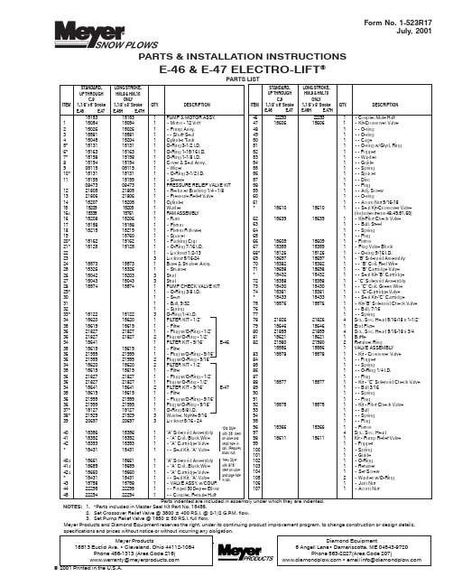
151********PUMP & MOTOR ASSY .115054150541• Motor - 12 Volt 215026150261• Pump Assy.315581155811•• Shaft Seal 415045152041Cylinder Tank 5*151********O-Ring 3-1/2 I.D.6*151********O-Ring 1-15/16 I.D.7*151********O-Ring 1-1/8 I.D.815194151941Cover & Seal Assy.905119051191• Wiper10*151********• O-Ring 3-1/2 I.D.1115199151991• Sleeve08473084731PRESSURE RELIEF VALVE KIT 1221805218051• Reducer Bushing 1/4 - 1/81321806218061• Pressure Relief Valve 1415207152051Cylinder 1515209152091Washer16a 153********RAM ASSEMBL Y 1615208152061• Ram 1715158151581• Piston1815219152191• Piston Follower 19157601• Spacer20*151********• Packing Cup 21*15125151251• O-Ring 7/16 I.D.221• Locknut 1/2-13233Locknut 5/16-242415573155731Base & Strainer Assy.2515326153261• Strainer 2615042152033Stud 2715043150433Stud2815574155741PUMP CHECK VALVE KIT 29*1• O-Ring 3/8 I.D.301• Seat311• Ball, 9/32321• Spring33*151********O-Ring 1/4 I.D.3415620156201FILTER KIT - 1/2"3515619156191• Filter3621827218271• Plug w/O-Ring - 1/2"3621827218272Plug w/O-Ring - 1/2"34156411FILTER KIT - 9/16"E-463515619156191• Filter3621999219991• Plug w/O-Ring - 9/16"3621999219992Plug w/O-Ring - 9/16"3415620156202FILTER KIT - 1/2"3515619156191• Filter3621827218271• Plug w/O-Ring - 1/2"3621827218271Plug w/O-Ring - 1/2"3415641156412FILTER KIT - 9/16"E-473515619156191• Filter3621999219991• Plug w/O-Ring - 9/16"3621999219991Plug w/O-Ring - 9/16"37*151********O-Ring 5/8 I.D.38*21929219293Washer, Nyltite 5/163920697206973Locknut 5/16 - 244015356153561"A" Solenoid Assembly 4115392153921• "A" Coil, Black Wire 4215393153931• "A" Cartridge Valve *15431154311•• Seal Kit, "A" Valve 40a 156********"A" Solenoid Assembly 41a 156********• "A" Coil, Black Wire 42a 156********• "A" Cartridge Valve *15431154311•• Seal Kit, "A" Valve 4315758157581• VALVE ASSY . w/COUP .4422295222951•• Forged 90 Degree Elbow 4522294222941•• Coupler, Female Half4622293222931• Coupler, Male Half 4715606156061• Kit-Crossover Valve 481•• O-ring 491•• O-ring 501•• Cage511•• O-ring w/Glyd. Ring 521•• Poppet 531•• Washer 541•• Guide 551•• Spring 561•• Spacer 571•• Disc 581•• Plug591•• Adj. Screw 601•• O-ring611•• Acorn Nut 9/16-18*156********•• Seal Kit-Crossover Valve (includes items 48,49,51,60)6215639156391• Kit-Pilot Check Valve 631•• Ball, Steel 641•• Spring 651•• Plug 6615609156091• Piston6715359153591• Plug Valve Block 68*151********•• O-ring 9/16 I.D.6915697156971• "B" Solenoid Assembly 7015382153821•• "B" Coil, Red Wire 7115698156981•• "B" Cartridge Valve *15432154321•• Seal Kit-"B" Cartridge 7215358153581• "C" Solenoid Assembly 7315430154301•• "C" Coil, Green Wire 7415381153811•• "C"-Cartridge Valve *15433154331•• Seal Kit-"C" Cartridge7515576155761• Kit-"B" Solenoid Check Valve 761•• Ball, 7/16771•• Spring7821826218264Scr., Soc. Head 5/16-18 x 1-1/2"7915646156461End Plate8021859218594Scr., Soc. Head 5/16-18 x 3/48115621156211Baffle8221980219802Retainer Ring155********VALVE ASSEMBLY 8315578155781• Kit - Crossover Valve 841•• Poppet 851•• Spring861•• O-Ring 1/4 I.D.871•• Plug8815577155771• Kit - "C" Solenoid Check Valve 891•• Ball 3/16901•• Spring 911•• Plug9215575155751• Kit - Pilot Check Valve 931•• Ball 941•• Spring 951•• Plug 9615366153661• Piston974Scr., Soc. Head9815611156111Kit - Pump Relief Valve 991• Poppet 1001• Spring 1011• Guide 1021• O-Ring 1031• Retainer 1041• Set Screw1052• Washer w/O-Ring 1061• Jam Nut 1071• Acorn NutForm No. 1-523R17July, 2001PARTS & INSTALLATION INSTRUCTIONSE-46 & E-47 ELECTRO-LIFT ®"Old Style"with 3/8" stem on valve and small hole in coil. (Requires brass nut)"New Style"with 9/16"stem on valve and large hole in coil.PARTS LISTSTANDARD-LONG STROKE-UP THROUGHHM-9 & HM-10C-9ONL YITEM1-1/8" x 6" Stroke 1-1/8" x 8" Stroke QTY . DESCRIPTIONE-46E-47E-46H E-47HSTANDARD-LONG STROKE-UP THROUGHHM-9 & HM-10C-9ONL YITEM 1-1/8" x 6" Stroke 1-1/8" x 8" Stroke QTY . DESCRIPTIONE-46E-47E-46H E-47HNOTES: 1. *Parts included in Master Seal Kit Part No. 15456.2.Set Crossover Relief Valve @ 3800 ± 400 P .S.I. @ 2-1/2 G.P .M. flow.3.Set Pump Relief Valve @ 1650 ± 50 P .S.I. full flow.Parts indented are included in assembly under which they are indented.Meyer Products and Diamond Equipment reserves the right, under its continuing product improvement program, to change construction or design details,E-46, E-46H, E-47 and E-47HExploded ViewNote: Oil seepage, if any, at O-ring (60)is normal, DO NOT attempt to stop thisseepage by further tightening of theAcorn Nut.GENERAL INFORMATIONBefore the Meyer Electro-Lift® unit is disassembled for repairs, make certain that all the maintenance procedures have been checked; refer to Owner's Manual.When the unit is to be overhauled, Master Seal Kit Part No. 15456 is required. This Kit contains all necessary Seals for rebuilding. NOTE: DO NOT REUSE OLD O-RINGS.When ordering parts, furnish Type of Unit, Part No., Name and Description.These instructions are intended as a guideline for overhaul of an E-46/E-47 Electro-Lift® unit.More detailed information covering principles of Operation, Troubleshooting, Disassembly and Repair are found in Electro-Lift® Service Manual 1-562. This is available for a nominal fee from your Meyer Distributor or directly from Meyer Products.DISASSEMBLY AND INSPECTION OF UNIT Drain fluid from the unit by removing Pressure Relief Valve (13) or Drain Plug (36). Clamp Sump Base (24) firmly into vise.1.To disassemble COVER ASSEMBLY, TANK, RAM &CYLINDER PARTS, remove three Locknuts (39).2.To disassemble MOTOR from PUMP, loosen Motormounting bolts, but DO NOT REMOVE.Note: Motor end plate to be held in place. Temporarily install two 1/4-20 nuts on the motor mounting bolts to keep motor intact. Remove nuts when reinstalling Motor to pump.3.To disassemble Pump from Base, remove three Locknuts(23).4.To disassemble VALVE BLOCK from BASE, remove Soc.Hd. Screws (78, 80 or 97).SUBASSEMBLIES - INSPECTION1.COVER ASSEMBLY, TANK, RAM & CYLINDER PARTS:a)Check Cover (8), and Base (24) castings for cracksand damage.b)Replace Wiper Seal (9) pressed in Cover (8).c)Inspect Sleeve (11), Piston (17), the Piston Follower(18), Spacer (19) for excessive wear. Replace PackingCup (20). Inspect Cylinder (14) for scoring and pittingin bore.d)Inspect Ram (16) for nicks and rust.2.MOTOR (1)Note: Complete Motor Assemblies are only availablefrom Meyer Products. Service and repair parts can bepurchased from your nearest authorized Prestolite orAmerican Bosch Service Stations.a)Prestolite Motor can be identified by a "Domed TopCover" and name "Prestolite" stamped on Motor Body.b)American Bosch Motors have a "Flat Top Cover" andno identifying marks.3.PUMP (2)DO NOT at any time disassemble this Pump. This will void the warranty.a)The damaged pump drive Shaft Seal (3) may beremoved by careful extraction with a pointed tool. Dipnew Seal in oil and with lip down, press into PumpHousing flush to 1/32 inch below face of boss.4.BASE (24)a)Remove and clean Solenoid (40) and inspect forexternal damage.b)Test Coil (41) for electrical continuity. Nominal Coilresistance is 9.6 ohms. Replace O-rings from Seal KitPart No. 15431 contained in Seal Kit No. 15456.c)To reassemble, carefully guide the Coil (41) over theValve Cartridge (42) and use the original External BrassNut.d)Remove and clean the Filter Screen (34) usingkerosene and blow out with air. Replace O-rings (33)from Seal Kit No. 15456.5.VALVE BLOCKSa)Remove items (69), (76) & (77). Clean "B" Solenoid(69) and inspect for damage. Disassemble CartridgeValve (71) and replace O-rings from Seal Kit No. 15432contained in Seal Kit No. 15456.b)Remove and clean "C" Solenoid (72) and inspect fordamage. Disassemble Cartridge Valve (74) and replaceO-rings and nylon back-up rings from Seal Kit No.15433 contained in Seal Kit No. 15456. Be certain O-rings and spacers are oriented properly.c)Test both Coils (70 & 73) for electrical continuity.Nominal Coil resistance is 3.7 ohms.d)Remove Plug (67) and Piston Assembly (66 or 96) andinspect the Piston for scratches. Replace O-ring (68)from Seal Kit No. 15456.e)Remove Pilot Check Valve Parts (62 or 92) and inspectall parts for damage.f)Remove Plugs (87) with caution as these are springloaded.g)Remove all parts of Item 47 or 83 and inspect fordamage. Replace O-rings from Seal Kit No. 15456. Setadjustable crossover to 3800 P.S.I. ± 400 P.S.I.h)Remove all parts of Item 88 and inspect for damage.i)With parts removed from Valve Block, clean and blowout with air to remove any foreign particles in Block.6.UNIT REASSEMBLYa)Before reassembling, make certain all components andsub-assemblies are clean and free from all dirt andother foreign material.b)When replacing parts, install (63), (64) & (65) or (93),(94) & (95) before installing Piston (66 or 96) and Plug(67).c)Motor mounting bolts must be sealed with Permatexor an all weather Type sealant.d)USE NEW SEALS AND M-1 FLUID WHENREASSEMBLING THE UNIT.d)Proper fluid level is 1-1/2" below filler hole. It must bechecked with Lift Ram fully retracted.。
- 1、下载文档前请自行甄别文档内容的完整性,平台不提供额外的编辑、内容补充、找答案等附加服务。
- 2、"仅部分预览"的文档,不可在线预览部分如存在完整性等问题,可反馈申请退款(可完整预览的文档不适用该条件!)。
- 3、如文档侵犯您的权益,请联系客服反馈,我们会尽快为您处理(人工客服工作时间:9:00-18:30)。
WARNING
Warning - In addition to possible serious injury or death, failure to follow the
indicated instruction may cause damage
to pump and/or other equipment.
etc.) be sure that :
pressures.
● Any pressure in the chamber has been completely
vented through the suction or discharge lines or other appropriate openings or connections.
figure 1 - GG, HJ, HL 4195-G Unmounted pump
INTRODUCTION
The illustrations used in this manual are for identification purposes only and should not be used for ordering parts. Secure a parts list from the factory or a Viking® representative. Always give complete name of part, part number and material with model number and serial number of the pump when ordering repair parts.
● The pump drive system means (motor, turbine, engine, etc.) has been “locked out” or otherwise been made non-operational so that it cannot be started while work is being done on the pump.
figure 2 - as, ak, al 4195-G Unmounted pump
CAUTION ! The 4195-G series is a UL listed pump. Any changes or repairs to the pump will void the UL listing. To maintain the UL listing, the pump will need to be replaced with a new pump or repaired and retested at the factory. If the UL listing is no longer required, refer to TSM 144 for repair instructions. These can be obtained from your authorized Viking Pump distributor.
D = Direct Drive
This manual deals exclusively with the 4195-G Series LP-Gas pumps. Refer to Figures 1 thru 10 for general configuration and nomenclature used in this manual.
TECHNICAL SERVICE MANUAL
VIKING LP-GAS PUMPS SERIES 4195-G SIZES GG - AL
SECTION PAGE ISSUE
TSM 442 1 of 10 B
CONTENTS
Introduction . . . . . . . . . . . . . . . . . . . . . . . . 1 Safety Information . . . . . . . . . . . . . . . . . . . . 2 Special Information . . . . . . . . . . . . . . . . . . . . 3 Maintenance . . . . . . . . . . . . . . . . . . . . . . . 3 Disassembly . . . . . . . . . . . . . . . . . . . . . . . 5 Assembly . . . . . . . . . . . . . . . . . . . . . . . . . 6 Thrust Bearing Adjustment . . . . . . . . . . . . . . . . 6 Pressure Relief Valve Instructions . . . . . . . . . . . 6 Supplementary Section . . . . . . . . . . . . . . . . . 8 Warranty . . . . . . . . . . . . . . . . . . . . . . . . 10
DO NOT exceed the pump’s rated pressure, speed, temperature, or change the system/duty parameters from those the pump was originally supplied, without confirming its suitability for the new service.
GG 4195-G HJ 4195-G HL 4195-G AS 4195-G AK 4195-G AL 4195-G
UNITS
Units are designated by the . unmounted pump model numbers followed by a letter(s) indicating drive style.
● You know what material the pump has been handling, have obtained a material safety data sheet (MSDS) for the material, and understand and follow all precautions appropriate for the safe
THE FOLLOWING SAFETY INSTRUCTIONS MUST BE FOLLOWED AND ADHERED TO AT ALL TIMES.
ห้องสมุดไป่ตู้
Symbol Legend :
Danger - Failure to follow the indicated
!
instruction may result in serious injury . or death.
!
BEFORE opening any liquid chamber (pumping chamber, reservoir, relief valve adjusting cap fitting,
WARNING
INSTALL pressure gauges/sensors next to the pump suction and discharge connections to monitor
VIKING PUMP, INC. • A Unit of IDEX Corporation • Cedar Falls, IA 50613 USA
SAFETY INFORMATION AND INSTRUCTIONS
IMPROPER INSTALLATION, OPERATION OR MAINTENANCE OF PUMP MAY CAUSE SERIOUS INJURY OR DEATH AND/OR RESULT IN DAMAGE TO PUMP AND/OR OTHER EQUIPMENT. VIKING’S WARRANTY DOES NOT COVER FAILURE DUE TO IMPROPER INSTALLATION, OPERATION OR MAINTENANCE.
The unmounted pump or pump unit model number and serial number can be found on a nameplate attached to the pump or base.
Model Number Chart
UNMOUNTED PUMPS
handling of the material.
DO NOT attempt to dismantle a pressure relief valve
!
BEFORE operating the pump, be sure all drive guards
!
are in place.
that has not had the spring pressure relieved or is mounted on a pump that is operating.
!
WARNING
USE extreme caution when lifting the pump. Suitable lifting devices should be used when appropriate. Lifting eyes installed on the pump must be used only to lift the pump, not the pump with drive and/or base plate. If the pump is mounted on a base plate, the base plate must be used for all lifting purposes. If slings are used for lifting, they must be safely and securely attached. For weight of the pump alone (which does not include the drive and/or base plate) refer to the Viking Pump product catalog.