Simufact forming 多核计算设置
simufact forming热处理工艺教程
simufact forming热处理工艺教程Simufact Forming热处理工艺教程欢迎各位读者进入Simufact Forming热处理工艺教程。
本篇文章将为您详细介绍使用Simufact Forming软件进行热处理模拟的步骤和方法。
第一步:软件安装与准备在进行热处理模拟之前,首先需要安装Simufact Forming软件并准备相关材料。
您可以从官方网站或其他授权渠道下载软件并进行安装。
同时,您还需要准备好相关材料的热物性参数、材料的应变硬化曲线等数据。
第二步:模型准备在进行热处理模拟之前,需要对待模拟的工件进行建模和几何设定。
Simufact Forming提供了各种几何建模工具,您可以根据实际情况选择合适的方法进行建模。
之后,您还需要设定材料属性和初始温度等参数。
第三步:网格划分在进行模拟过程中,需要将工件离散成有限元网格,以便进行数值计算。
Simufact Forming软件提供了强大的网格划分功能,您可以根据模型的复杂程度和要求选择合适的网格划分方法和密度。
第四步:选择热处理模块Simufact Forming软件提供了多种热处理模块,包括表面淬火、沸腾淬火和均匀加热等。
根据实际需要,您可以选择合适的模块进行模拟。
同时,您还可以根据需要自定义设置热处理的参数,如温度曲线、冷却介质等。
第五步:设置热处理参数在进行模拟之前,需要设置热处理的相关参数。
这些参数包括热处理温度、冷却速率、保温时间等。
Simufact Forming软件提供了直观的界面和指导,您可以根据实际需求设定这些参数,并进行相应的优化。
第六步:模拟运行当所有参数设置完毕后,可以开始进行模拟运行。
Simufact Forming软件根据所设定的参数和模型,进行热处理模拟计算,并生成相应的结果。
您可以通过结果文件进行后续的分析和评估。
第七步:结果分析与优化模拟计算完成后,您可以通过Simufact Forming软件提供的结果分析功能,对模拟结果进行评估和分析。
simufact.Forming10.0新功能介绍
S i m u f a c t .f o r m i n g 10.0simufact.forming 10.0u总览u改进前处理功能u 新功能菜单u 更加灵活的定义u改进后处理功能u改进并行计算能力u改进模具应力分析功能u改进钣金成形模块u改进机构运动模块u 环轧设备运动u 开坯锻设备运动u改进网格划分功能uGP-GUI 界面u 帮助u 改进实例分析u 新用户帮助手册S i m u f a c t .f o r m i n g 10.0总览S i m u f a c t .f o r m i n g 10.0General remarksu Simufact.forming 10.0 基于§MSC 软件Marc2010和Dytran2010 §Windows 界面支持更多功能§GP-GUI 基于Mentat2010§CAD 导入基于CADfix-Version 8.0 ServicePack 1支持最新的CAD 软件版本§全新的图形界面§新的安装和文件结构§Windows 32bit and 64bit (XP , Windows 7)Linux64 (no Forming-GUI)S i m u f a c t .f o r m i n g 10.0Installationu 所有的设定都储存在一个INI 文件~USER/ AppData\Roaming\Simufact /simufact.forming_10.0.ini ØWill allow to copy the installation to other computerØUsers can use the same settingsØThe INI-file will be written when you start the first time the GUI u Ini-File can directly be copied for other users u Whole installation can be copied or mirrored without a new setupon other computersS i m u f a c t .f o r m i n g 10.0Default Unit-Systemu Default UNIT-System after the installation is Si-mm-UnitAll examples are based on this systemUnit-System can be reset by usingS i m u f a c t.f o r m i n g 10.0u Add stl-Import for CAD Preview/Import with CAD-repair functionalitybased on CADFixu Latest Version from CADFix 8.0 Service Pack1 are implemented CADFix InterfaceIntelligent model quality diagnostics and repair Automatical defeaturingAutomaticalrepair Support Assemblies Native Interfaces CA TIA V5/R20CA TIA V4/ 4.1.X, 4.2.X Pro/Engineer Wildfire 4SolidWorks 2009Unigraphics NX7Inventor 2010Neutral Interfaces ACIS R20IGES 5.3STEP AP203 & AP214Parasolid V22VDASF 2.0STLS i m u f a c t .f o r m i n g 10.0Improved View CapabilitiesS i m u f a c t .f o r m i n g 10.0u Improved predefined view concept u 3 different View and Zoom settings can be stored 1.Global for all GUI ’s which are opened from the user 2.Stored for the current project 3.Stored for each processàThis option allows to define more flexible the view and zoomfactor for a more easy post processing and for variationsS i m u f a c t .f o r m i n g 10.0u New global setting for edge angle for outline view Edge angle = 5 deg Edge angle = 30 degS i m u f a c t .f o r m i n g 10.0u New option to control Cache for Graphicusupport huge models u Reduce out-of-memory problemsOFF : All results will not hold in the memory ON : All results are hold in th memory.Current:current used memory Clear: Clear all result information in memory Clear cache between animation steps:Results are removed from memory after each animation stepSimufact.forming1.u New option to activate filters in process and inventory windowu This allows the user to show or hide objects andprocesses very easy and concentrate on the things he want to do§eg. hide all used geometriesS i m u f a c t .f o r m i n g 10.0u Define number of entries for the “open project list ” (default: 4)S i m u f a c t .f o r m i n g 10.0uNew Cutting function with u There is a new option to decided which part should be cut 1.All components (default)2.All except workpiece 3.Only workpieceS i m u f a c t .f o r m i n g 10.0Improved Preprocessing CapabilitiesS i m u f a c t .f o r m i n g 10.0uStore comment for the projectS i m u f a c t .f o r m i n g 10.0uImproved support for default settings for process types uSettings are stored in ~InstallDir/sfForming/setting/processtype.ini u Following parameters can be predefined by the user§Default Solver and dimension, cold/or hot used for the Process§Predefined names for the tools depending on Solver and hot/cold §Number of tools used for the Process depending on Solver and hot/cold§ElementSize depending on Solver §Number of Outputresults §New: Convergence control for FE §Control parameter for forming control FE/FV §Meshertype §Ambient temperatureS i m u f a c t .f o r m i n g 10.0u Names for most objects are based on the type now including theprocess type and solver information (FE/FV)u Temperature of the die and workpiece are added to the name by defaultuNew ICON to open model view windowSim u f a c t .f o r m i n g 10.0u New Interface to Thermoprof from ABP Induction§Import temperature field based on the inductive heatingcalculation from ThermoprofSi m u f a c t .f o r m i n g 10.0u New Interface to ProCast Casting simulation softwareu Import geometry and blow whole distributionS i m u f a c t .f o r m i n g 10.0Improved Preprocessing Capabilities/Modelu Basic geometry body Cylinder are created symmetric tothe axisS i m u f a c t .f o r m i n g 10.0Improved Preprocessing CapabilitiesuEnlarge geometry in one direction to close gaps §Sometime you have small gaps in your process which are not useful for the simulation §You can enlarge it easy by using enlarge option and substitute the geometry which the new enlarged geometry geometry-EEnlarged filename is: *-ES i m u f a c t .f o r m i n g 10.0u Redesign of Positioner menuu The user can directly choosebetween Standard (with gravity)Positioner and Translation onlyu Add menu also for right mouseclickS i m u f a c t .f o r m i n g 10.0u New Function to rotate part based on the coordinate systemuRight mouse click on part 1.Relative to current position 2.absoluteS i m u f a c t .f o r m i n g 10.0uNew Interface to JMatPro §JMatPro will provide material data based on the chemical composition for a huge range and a lot of materials §This allows more material sensitive simulations § A lot of information are available also for later use (TTT etc)§JMatPro will have an export function to simufact at the endof the yearS i m u f a c t .f o r m i n g 10.0uUnits are taken from predefined settings (default mm and mm/sec) for the definition of presses u All presses which are available for FV Solver are alsoavailable for FE-Solver with all functionalities§Screw press §Counter blow Hammer §Scotch Yoke Driveu Hammer and Screw press are improved, so that the elastic effect from the dies can be taken into account uNew: Velocity table based on the diameter of a ring. This allows full flexibility for ring rolling applications uNew: Force velocity controlled press uNew: radial press with table driven velocity of the upper die (only for FE-Solver)u Presses can be mixed for FE solver (eg. CrankPress+Table)S i m u f a c t .f o r m i n g 10.0uHammer and Screw press §Support for FE and FV all functionalities §Counterblow §including efficiency factor constant variable variable with clutch §New feature to support spring effect of the dies (advanced settings)uScotch Yoke drive Press §Support for FE and FVSimufact.forming1.u New: Force velocity controlled press§Can be defined by using a table based on force/velocity§Velocity direction is controlled in forming menu§stroke has to be defined as well§Can be used similar to hydraulic pressResult from simulation:S i m u f a c t .f o r m i n g 10.0u New: radial press with table driven velocity of the upper die§Rotation path are defined based on a circle or rosette path §Can be combined with other pressesS i m u f a c t .f o r m i n g 10.0u Move friction or heat object to the processu all unassigned objects will get this friction/heatS i m u f a c t .f o r m i n g 10.0uThe die types are improved for the use with the FE-solver to make it more flexible uYou will find now:ØDie Spring ØDie Insert ØGeneric Spring ØDie Spring: The stiffness and/or Force can be defined depending on the time or displacementS i m u f a c t .f o r m i n g 10.0ØDie Insert: redefined to make it more easy to use and fully flexible. The movement can be:§Free §Fixed §Coupled with a Press (table based)§Or coupled with a generic springS i m u f a c t .f o r m i n g 10.0ØGeneric spring: a generic spring can be defined in all 3 translation directions (global or local coordinate system)and in the rotation direction as a torsion spring ØStiffness or force can be defined depending on displacement or force ØThe generic spring should be use together with a die insertS i m u f a c t .f o r m i n g 10.0Improved Preprocessing Capabilities/Contact tableu Contact tableu New: Initial stress free projection (the contact is calculated at thebeginning without a stress calculation), this is needed if you have initial penetration based on the discretization and you want to bring the parts in contact, often used if parts are glued togetherü.S i m u f a c t .f o r m i n g 10.0u Particleumost element variables can be selected for pathplotS i m u f a c t .f o r m i n g 10.0u The forming dialog is rewritten based on the new conceptwith short descriptionsuThe direction can be defined via arrows u Stroke or Time (depends on the presstype) can be setindependent from the time in the table to simulate only a part firstS i m u f a c t .f o r m i n g 10.0New terminate criteriau New terminate criteria for FE•max force for press as sumall forces of the diesof the press are cumulated§and/ormax force for each bodyand one directionS i m u f a c t .f o r m i n g 10.0u New features for sub stage dialog to support morecomplex processes very easyS i m u f a c t .f o r m i n g 10.0u You can deactivate a tool which are not used for thecalculation of the positioning of the workpiece in the first stepØEg. The blankholder is a fixed tool and have to bedeactivate for the positioning of the workpieceS i m u f a c t .f o r m i n g 10.0uYou can trim during the forming process with additional trimming tools ØYou can trim after different strokes with different tools ØIf they are not defined with a press, then they are used only for the trimming operation This allows you to form the part, trim it with a different tool and to go on with the forming processS i m u f a c t .f o r m i n g 10.0Trimmer (Cutter-1)CutterForming until 60 mm Trimming with Cutter-1Forming up to 70 mmuForming-Trimming-Forming in one runS i m u f a c t .f o r m i n g 10.u You can simulate a forward and backward motion withthe same press to have a whole cycleØYou can add a movement of a predefined press only forthe backward movementS i m u f a c t .f o r m i n g 10.0uForming process can be done in one whole cycle with forward and backward movement, kinematic for counterpunch can be deactivated for forming forward part u This is helpful for cold forming and sheet forming application where a deformations are also taken into a count in thebackward motion partS i m u f a c t .f o r m i n g 10.0 1.You can define a max. thickness for potsprocessing, so that the legend are scaled automatically, you can change this later as well 2.You can define max. distance for “Distance to Die ” Postvariabel (same as for FV), as a max Threshold 3.For 3D axissymmetric problem you can define radial&tangential results, so that you will get the vectors/tensors also in a cylindrical coordinate system 4.You can define own nodal and/or element variables which you can output by using subroutines. The names can be defined individuallyS i m u f a c t .f o r m i n g 10.0u New step size control based on the max displacementØThis can be defined also by default from the solver ØIt makes a simulation more robust, but needs generallymore stepsS i m u f a c t .f o r m i n g 10.0uSupport new solver ØThe solvers are improved ØMultiplethreading (parallel solving) are supported from ØMultifrontal Sparse solver ØCASI Solver (very fast)ØParadiso Solver ØNew: Mumps SolverØSome have a new option to speed up the solution time inthe interfaces when using DDM parallel optionS i m u f a c t .f o r m i n g 10.0u Support UsersubroutineØUser can select own subroutine and build an own version ØNeed a valid fortran licenseIntel(R) Fortran Compiler Version 10.1Requires:Microsoft(c) Visual Studio 2005 Service Pack 1Microsoft(c) Platform SDK for Windows Server 2003 SP1S i m u f a c t .f o r m i n g 10.0uThe parallel menu is redesigned and will support all parallel options ØWorkpiece only Øwill use multiple domains with remeshing of the workpiece Øonly the workpiece can be a meshed body ØMultiple bodies without remeshing Øwill use multiple domains for all meshed bodies Øwithout remeshing ØMultiple bodies with remeshing Øeach meshed body is assigned to one domain Øremeshing possibleS i m u f a c t .f o r m i n g 10.0u Starting with simufact.forming 10.0 a report can be generated in XML-format about the processuIncludes all information about the process u and the simulation parameteru informations are linkedu preview is included in the GUI。
simufact forming热处理
simufact forming热处理热处理是一种通过加热和冷却金属材料来改变其物理性质的工艺。
它可以改善材料的力学性能、耐磨性和耐腐蚀性,同时提高材料的可加工性和耐用性。
在制造业中,热处理技术被广泛应用于各种行业,如汽车制造、航空航天、能源等。
本文将重点介绍一个专业的热处理仿真软件——Simufact Forming。
Simufact Forming是一款专为金属成形工艺而设计的仿真软件。
它利用有限元方法,在计算机中模拟金属材料在热处理过程中的力学行为。
通过Simufact Forming,用户可以预测和优化热处理过程,以达到所需的材料性能。
下面,我们将逐步回答关于Simufact Forming热处理的问题。
第一步:软件安装和设置在使用Simufact Forming之前,用户需要先安装软件并进行相关设置。
安装过程通常很简单,用户只需按照安装向导的指示执行即可。
设置方面,用户可根据自己的需求进行定制,如选择材料类型、确定热处理参数等。
第二步:几何建模在进行任何仿真分析之前,我们需要先对所研究的材料进行几何建模。
Simufact Forming提供了多种几何建模工具,包括基本几何体创建、实体建模和导入CAD文件等。
用户可根据实际情况选择最适合的建模方法,以保证仿真结果的准确性和可靠性。
第三步:网格划分网格划分是有限元仿真中非常重要的一步。
通过将材料划分为许多小的单元,Simufact Forming可以更好地模拟材料的本质行为。
在网格划分过程中,用户既需要考虑模型的复杂程度,又需要平衡仿真精度和计算效率的关系。
通过合理调整网格密度和质量,用户可以得到准确而高效的仿真结果。
第四步:材料本构模型和边界条件定义在进行真实的热处理仿真之前,我们需要对材料的本构行为和边界条件进行定义。
Simufact Forming提供了多种材料本构模型,如弹塑性、热弹塑性、热弹性等。
用户可根据具体情况选择最合适的模型,并指定材料的物理性质和变形规律。
simufact.forming中文手册教程

SuperForge2005使用手册内容:参数设置,试验分析,结果分析编制:王 毅部门:工程部时间:2005.7.28~2005.8.10目录一、计算机配置及相关参数设置和结果简介-----------------------------11.计算机配置情况:-----------------------------------------------12.软件主要参数设置说明-------------------------------------------13.软件运行结果的说明---------------------------------------------2二、SUPERFORGE2005操作步骤详解------------------------------------31.生成STL模型文件------------------------------------------------32.在S UPER F ORGE环境下设置各参数-------------------------------------53.参数调入设计树-------------------------------------------------84.运行-----------------------------------------------------------95.结果显示-------------------------------------------------------9三、关键参数设置试验及分析----------------------------------------101.STL文件精度的设置--------------------------------------------102.模具类型的设置------------------------------------------------123.网格长度的设置------------------------------------------------144.摩擦系数的设置------------------------------------------------165.水压机速度设置------------------------------------------------186.材料的定义----------------------------------------------------20四、结果显示与分析------------------------------------------------221.接触应力(C ONTACT P RESSURE)-------------------------------------222.其他结果说明--------------------------------------------------25 结论--------------------------------------------------------------27一、计算机配置及相关参数设置和结果简介SuperForge2005试用过程是在2004使用的一定经验之上进行的,对于我司的产品的一些参数,大体上已经有一定的积累,记录如下:1. 计算机配置情况:CPU:奔腾D520(64位2.66主频)内存:2G显卡:ATI X700主板:Intel 915G硬盘:120G(SATA)2. 软件主要参数设置说明按照我司产品的整个制作过程,对软件运行的整体参数按步骤作如下设置:①模具的类型选择:Backward Extrusion (或者closed die)②输入模具及锻件文件为STL格式(具体制作过程见附录)Model->From fileSTL文件在制作时会因为误差和角度的不同,在本文中,若不作特殊说明则:“粗”是指误差为0.0557mm,角度为30°的STL文件;“良”是指误差为0.0215mm,角度为10°的STL文件;“精”是指误差为0.0023mm,角度为0.5°的STL文件。
阿毅工作室

Simufact.formingV8 SP2手动提交计算方法Simufact.Forming V8 SP2不能计算,直接提交计算后,会弹出以下的对话框,花了很多时间,也没有在注册表里面搞定,后来只能看是否能够手动提交计算,在今天上午终于搞成功了,呵呵,详细的教程如下:1:更改Simufact.forming的设置:在tool菜单,选择Options选项,打开如下对话框,选择Environment手动指定计算的求解器的目录位置:Finite V olume 是G:\CAE\Femutec\simufact\forming\8.0\sfDytran\bin-mp\sfDytranmp.exe其中(G:\CAE\Femutec\simufact\forming\8.0\sfDytran\bin-mp\)软件安装目录Finite Element为:G:\CAE\Femutec\simufact\forming\8.0\sfMarc\bin\sfmarc.exe点击应用确定。
完成上面的步骤后,前处理完毕后,提交计算,会出现以下错误对话框:此时,就可以在计算文件所在目录里面进行手动的设计,并启动计算,方法如下:1:进入到计算文件所在的目录:继续进入:Project注意上面的目录名字,后三个目录:编辑runsf.bat批处理文件,之所以出错,就在于这个文件在自动生成时有一个注册表项没有读到,不知道是否为DB_PJ的原因?在阴影部分前面添加上run_sfdytran.bat的具体位置(安装目录),也就是将前面添加G:\CAE\Femutec\simufact\forming\8.0\sfDytran\。
保存,运行runsf.bat就可以计算了,~~~~~~~~~~~~~~~~~~~~OK~~~~~~~~~~~~~~~~~~~~~~~~~~~!!更多精彩内容阿毅工作室/space/?uid=1247。
MATLAB分布式并行计算服务器配置和使用方法

MATLAB分布式并行计算服务器配置和使用方法为了配置MDCS,需要按照以下步骤进行操作:1.安装MATLAB:首先,在每台计算机上安装MATLAB软件,并确保每台计算机上的MATLAB版本相同。
2.安装MDCS:在一台计算机上安装MDCS,此计算机将被配置为MDCS 整个系统的管理节点。
3.创建配置文件:在管理节点上创建一个配置文件,以指定各个计算节点的信息和所需资源。
二、配置计算节点1.安装MATLAB:在每台计算节点上安装相同版本的MATLAB。
2.启动MDCS:在每台计算节点上启动MATLAB,并在MATLAB命令窗口中输入以下命令启动MDCS:```matlab```第一行命令禁用本地使用 Mpiexec 命令,第二行命令启用本地使用Mpiexec 命令。
3.连接到管理节点:在计算节点上,使用命令行输入以下命令连接到管理节点:```matlab```4.配置计算工作文件夹:在计算节点上,使用以下命令配置计算工作文件夹:```matlab```其中,‘/path/to/temp/dir’ 是计算节点上的临时文件夹路径。
三、使用MDCS配置完MDCS后,可以使用以下方法将MATLAB作业提交到并行计算服务器上:1. 使用 parfor 循环:将需要并行计算的代码块放在 parfor 循环中,并使用以下命令提交作业:```matlab>> parfor i = 1:numIterations>>%并行计算代码>> end```2. 使用 batch 命令:使用 batch 命令将需要并行计算的代码封装成一个函数,并将其提交给并行计算服务器:```matlab>> job = batch(‘filename’,‘matlabpool’, numWorkers)```其中,‘filename’ 是要执行的 MATLAB 函数文件名,‘numWorkers’ 是并行计算服务器上的计算节点数量。
simufact13.3多核并行分析设置
现在的PC即使是单机单CPU也会有多核多线程,如果计算时不启用并行运算,计算效率会很低,会花更长时间,而且也浪费很多硬件资源,所以目前主流的CAE软件都会支持单机并行运算或者多机并行运算。
SimuFact.Forming 13.3已经发布半年多了,这个版本的细节部分有很多的更新,在并行计算领域,这个版本有比较大变化,设置更加方便了,下面做一下详细的说明。
SimuFact.Forming软件有FE和FV两种求解器,目前大部分计算都是用FE求解器,FE求解器实际就是MARC,这两种求解器都支持并行运算。
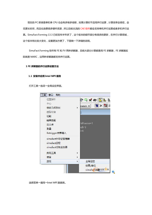
1 FE求解器的并行运算设置方法1.1 安装并启用Intel MPI服务打开工具→选项→全局设定界面。
选择菜单→通用→Intel MPI数据库。
点击注册MPI账户,这里输入具有管理员权限的用户名和密码(可以为域用户)。
输入完成后点Register按钮;点OK退出。
然后点击启用MIP服务!1.2 设置FE并行运算整体模拟设置完毕后点击成形→菜单→并行,并行前打勾。
这里有两个地方需要设置:域的数量和共享内存并行。
假如分析用的工作站为双CPU、8核心、16线程(license许可最大数量16),可以做如下设置:域数量8;共享内存并行1;CPU核心激活8;利用率:50%。
域数量2;共享内存并行4;CPU核心激活8;利用率:50%。
域数量1;共享内存并行8;CPU核心激活8;利用率:50%。
CPU核心激活=域数量*共享内存并行核数。
一般情况下,推荐域数量1,共享内存并行为CPU总核数。
域数量为FE(MARC)求解器独有的一项技术,可以将分析工件划分成几个区域进行分析,以前单CPU 的年代主要用于多计算机并行分析;共享内存并行,Intel提供的计算软件直接调用多核或者多CPU资源的一项技术;总而言之,在license许可的数量(本地主机上可以用的核数许可限制里面的数值)域和共享内存并行的乘积小于等于本地主机的最大cpu核数;上面两个步骤完成后,就可以提交计算,并利用本地主机的多核进行并行计算了,而软件能够调用的CPU核数取决你设置的多少!(域数量直接体现是:假如设置为2,就会有2个marc求解器线程出现,如果设置为1,就只有一个marc求解器线程,然后出现的MARC线程调用的CPU核数为设置的内存并行数量)1.3 不同设置的计算效率对比同样的激活核数,不同是设置方式计算时间会有略微的差异。
智能融合2多核系统控制器时钟配置指南说明书

SmartFusion2 MSS Clocks ConfigurationTable of ContentsIntroduction . . . . . . . . . . . . . . . . . . . . . . . . . . . . . . . . . . . . . . . . . . . . . . . . . . . . . . . . . . . . . . . . . . . . . . 3 System Clocks . . . . . . . . . . . . . . . . . . . . . . . . . . . . . . . . . . . . . . . . . . . . . . . . . . . . . . . . . . . . . . . . . . . . . . . . . . . . . 3 Advanced Options . . . . . . . . . . . . . . . . . . . . . . . . . . . . . . . . . . . . . . . . . . . . . . . . . . . . . . . . . . . . . . . . . . . . . . . . . . 51System Clocks Configuration. . . . . . . . . . . . . . . . . . . . . . . . . . . . . . . . . . . . . . . . . . . . . . . . . . . . . . . . . 6 MSS CCC Clock Source . . . . . . . . . . . . . . . . . . . . . . . . . . . . . . . . . . . . . . . . . . . . . . . . . . . . . . . . . . . . . . . . . . . . . 6 Cortex-M3 and MSS Main Clock (M3_CLK) . . . . . . . . . . . . . . . . . . . . . . . . . . . . . . . . . . . . . . . . . . . . . . . . . . . . . . 7 MDDR Clocks (MDDR_CLK and DDR_SMC_FIC_CLK) . . . . . . . . . . . . . . . . . . . . . . . . . . . . . . . . . . . . . . . . . . . . . 7 MSS APB_0 and APB_1 Sub-busses Clocks (APB_0_PCLK and APB_1_PCLK) . . . . . . . . . . . . . . . . . . . . . . . . . 7 FPGA Fabric Interface Clocks (FIC_0_CLK and FIC_1_CLK) . . . . . . . . . . . . . . . . . . . . . . . . . . . . . . . . . . . . . . . . 72Advanced Options . . . . . . . . . . . . . . . . . . . . . . . . . . . . . . . . . . . . . . . . . . . . . . . . . . . . . . . . . . . . . . . . . 9 PLL Lock(s) Advanced Options . . . . . . . . . . . . . . . . . . . . . . . . . . . . . . . . . . . . . . . . . . . . . . . . . . . . . . . . . . . . . . . . 9A Product Support. . . . . . . . . . . . . . . . . . . . . . . . . . . . . . . . . . . . . . . . . . . . . . . . . . . . . . . . . . . . . . . . . . 10Customer Service . . . . . . . . . . . . . . . . . . . . . . . . . . . . . . . . . . . . . . . . . . . . . . . . . . . . . . . . . . . . . . . . . . . . . . . . . 10 Customer Technical Support Center . . . . . . . . . . . . . . . . . . . . . . . . . . . . . . . . . . . . . . . . . . . . . . . . . . . . . . . . . . . 10 Technical Support . . . . . . . . . . . . . . . . . . . . . . . . . . . . . . . . . . . . . . . . . . . . . . . . . . . . . . . . . . . . . . . . . . . . . . . . . 10 Website . . . . . . . . . . . . . . . . . . . . . . . . . . . . . . . . . . . . . . . . . . . . . . . . . . . . . . . . . . . . . . . . . . . . . . . . . . . . . . . . . 10 Contacting the Customer Technical Support Center . . . . . . . . . . . . . . . . . . . . . . . . . . . . . . . . . . . . . . . . . . . . . . . 10 ITAR Technical Support . . . . . . . . . . . . . . . . . . . . . . . . . . . . . . . . . . . . . . . . . . . . . . . . . . . . . . . . . . . . . . . . . . . . . 11IntroductionThe MSS Clock Conditioning Circuitry (MSS CCC) provides a single place where all clocks related to the MSS and the communication between the MSS and the FPGA fabric can be configured.The MSS_CCC configurator is organized into tabs: System Clocks and Advanced Options (Figure 1).System ClocksThe System Clocks tab (Figure 2) enables you to configure/view:•The MSS CCC clock source CLK_BASE. The Configurator computes the frequency for you based on how the other clocks are configured.•The main MSS clock M3_CLK–Enter a value below 167 MHz to drive the Cortex-M3 Processor.–This is a limitation of the Cortex-M3.•The MDDR related clocks (MDDR_CLK and DDR_SMC_FIC_CLK)–MDDR_CLK and DDR_SMC_FIC_CLK must be between 20 MHz and 334 MHz.•The MSS APB_0 and APB_1 Peripheral clocks (APB_0_CLK and APB_1_CLK)–Choose a divisor of 1, 2, 4 or 8 to divide into the M3_CLK frequency to get the APB_0_CLK and APB_1_CLK frequency you want.•The two Fabric Interface (FIC) clocks (FIC_0_CLK and FIC_1_CLK)–Choose a divisor of 1, 2, 4, 8, 16 or 32 to divide into the M3_CLK frequency to get theFIC_0_CLK and FIC_1_CLK frequency you want.Figure 1 •MSS CCC ConfiguratorOnly the clocks used in your design are editable for configuration in the MSS CCC configurator. Make sure to enable and correctly configure all the MSS sub-blocks you intend to use in your design beforeconfiguring the MSS CCC sub-block. What can be configured and how (rules) depends on what is being used; see "System Clocks Configuration" on page 6 for details.The System Clocks tab displays a high level block diagram of your design displayed based on what you have enabled/disabled/configured in the MSS configurator. The block diagram shows the different clock domains (each clock domain is a different color) within the MSS as well as the clock domains that cross into the FPGA fabric. If you click any of the clocks (blue labels) you will see that particular clock domainFigure 2 •System Clocks Tabhighlighted on the block diagram Figure 3 shows the M3_CLK clock domain highlighted. It shows what components this clock is driving.Advanced OptionsYou can also configure more advanced options related to the PLL LOCKs using the Advanced tab. See "Advanced Options" on page 9 for a summary.Figure 3 •M3_CLK Domain Highlighted1 – System Clocks ConfigurationThe System Clocks tab (Figure 1-1) enables you to configure:•The MSS CCC clock source CLK_BASE •The main MSS clock M3_CLK •The MDDR related clocks (MDDR_CLK and DDR_SMC_FIC_CLK)•The MSS APB_0 and APB_1 Peripheral clocks (APB_0_CLK and APB_1_CLK)•The two Fabric Interface (FIC) clocks (FIC_0_CLK and FIC_1_CLK)MSS CCC Clock SourceIn normal operating mode (non Flash*Freeze) the MSS CCC is configured to be sourced from the FPGA fabric via the CLK_BASE port.If you use any of the FIC clocks (DDR_SMC_FIC_CLK, FIC_0_CLK and FIC_1_CLK), CLK_BASE is automatically set at the lowest frequency of any of the used FIC clocks and is not editable. In this case, when MSS outputs and inputs are to/from the fabric, the MSS I/Os are synchronous to CLK_BASE. For a more comprehensive system level view of the clocking methodology for interfacing the MSS and the FPGA fabric through the MSS FICs, refer to the SmartFusion2 MSS Creating a Design using MSS Fabric Interfaces document.If none of the FIC clocks are used, the CLK_BASE frequency is editable and you can select a clock frequency between 1 MHz and 200 MHz. In this case, the MSS I/Os are asynchronous.If CLK_BASE is sourced by a PLL in the FPGA fabric, you should connect the PLL LOCK signal from that fabric CCC to the MSS CLK_BASE_PLL_LOCK. When the chip system controller boots the device (atFigure 1-1 •System Clocks Configuration TabPoR or when the external pin DEVRST_N has been asserted/de-asserted) it monitors the external PLLLOCK as well as the internal MPLL LOCK and only switches to the clock configurations defined in thisconfigurator when the PLL have a stable lock.Cortex-M3 and MSS Main Clock (M3_CLK)The main clock for the Cortex-M3 and the MSS is M3_CLK; you must define its frequency.The following rules must be satisfied and are checked by the MSS_CCC configurator as you enter afrequency for M3_CLK:1.The M3_CLK frequency must be less than or equal to 167 MHz.2.The MDDR_CLK frequency must be less than or equal to 333 MHz.3.If the CAN peripheral is used M3_CLK must be a multiple of 8 MHz.4.If the USB peripheral is used M3_CLK must be greater than 30.1 MHZ.MDDR Clocks (MDDR_CLK and DDR_SMC_FIC_CLK)When the MDDR sub-block is configured as a DDR interface:•The MDDR_CLK drives the DDR controller and the DDR Bridge in the MSS. You can select this clock to be a multiple - 1, 2, 3, 4, 6 or 8 - of the main MSS clock M3_CLK.•The DDR_SMC_FIC_CLK drives the DDR FIC slave interface and defines the frequency at which the FPGA fabric sub-system connected to this interface is intended to run. You can select thisclock to be a ratio - 1, 2, 3, 4, 6, 8, 12, or 16 - of MDDR_CLK. To enable this, you need to enableFabric Interface Settings (i.e., FIC64) in the MDDR configurator.•If MDDR_CLK ratio to M3_CLK is a multiple of 3, DDR_SMC_FIC_CLK's ratio to MDDR_CLK must also be a multiple of 3, and vice versa. The configurator issues an error if this requirement isnot met. This limitation is imposed by the internal implementation of the MSS CCC.When the MDDR sub-block is configured as a Soft Memory Controller (SMC) interface:•The MDDR_CLK drives the DDR Bridge in the MSS. It is automatically set by the configurator to be equal to M3_CLK and is not editable.•The DDR_SMC_FIC_CLK drives the SMC master fabric interface. It is automatically set by the configurator to be equal to M3_CLK and is not editable.MSS APB_0 and APB_1 Sub-busses Clocks (APB_0_PCLK and APB_1_PCLK)There are two internal APB sub-busses in the MSS: APB_0 and APB_1. Each of these sub-bussesperipheral is clocked by APB_0_CLK and APB_1_CLK, respectively. These clocks are derived from themain MSS clock M3_CLK. Each APB clock can be programmed individually as M3_CLK divided by 1, 2,4 or 8.Note:Some peripherals may require a slower Peripheral clock (PCLK) to achieve certain configurations.Changing the APB sub-bus PCLK affects all peripherals present on that bus.FPGA Fabric Interface Clocks (FIC_0_CLK and FIC_1_CLK) For applications where the AMBA fabric Interface is used to connect to a soft AMBA sub-system (softbus/bridge/peripheral cores), the FIC sub-system clocks (FIC_0_CLK and FIC_1_CLK) must beconfigured such that the generated frequencies meet the timing requirements of the FPGA logicimplemented in the fabric for each FIC sub-system.The FPGA fabric clocks, when used, can only be the MSS clock divided by 1, 2, 4, 8, 16 or 32. You mustverify that the FPGA fabric timing for each FIC sub-system meets the selected fabric clock frequency byperforming timing analysis of your design using SmartTime.For a more comprehensive system level view of the clocking methodology for interfacing the MSS and the FPGA fabric through the MSS FICs, refer to the SmartFusion2 MSS Creating a Design Using MSSFabric Interfaces document.2 – Advanced OptionsThe Advanced Options tab enables you to configure Advanced PLL Lock Options:PLL Lock(s) Advanced OptionsLock Count (Delay) - Sets the number of CLK_BASE (reference clock) clock cycles by which the lock is delayed after the MPLL has reached the lock condition. The default value is 32.Lock Window (ppm) - Configures the maximum phase error allowed for the MPLL to indicate it has locked. The lock window is expressed as parts per million (ppm) of the reference frequency. The default value is 8,000.You can enable interrupts to the Cortex-M3 to monitor assertions and de-assertions of the MPLL lock.You can expose the MPLL LOCK signal to the FPGA fabric and use it as part of your design to monitor the health of the MPLL (loss or lock may require special handling by your application).You can enable interrupts to the Cortex-M3 to monitor assertions and de-assertions of the CLK_BASE PLL lock if you are monitoring this signal by checking the Monitor FPGA Fabric PLL Lock (CLK_BASE_PLL_LOCK) checkbox (Figure 3).Figure 2-1 •Advanced Options Configuration TabA – Product SupportMicrosemi SoC Products Group backs its products with various support services, including CustomerService, Customer Technical Support Center, a website, electronic mail, and worldwide sales offices.This appendix contains information about contacting Microsemi SoC Products Group and using thesesupport services.Customer ServiceContact Customer Service for non-technical product support, such as product pricing, product upgrades,update information, order status, and authorization.From North America, call 800.262.1060From the rest of the world, call 650.318.4460Fax, from anywhere in the world, 650.318.8044Customer Technical Support CenterMicrosemi SoC Products Group staffs its Customer Technical Support Center with highly skilledengineers who can help answer your hardware, software, and design questions about Microsemi SoCProducts. The Customer Technical Support Center spends a great deal of time creating applicationnotes, answers to common design cycle questions, documentation of known issues, and various FAQs.So, before you contact us, please visit our online resources. It is very likely we have already answeredyour questions.Technical SupportFor Microsemi SoC Products Support, visit /products/fpga-soc/design-support/fpga-soc-support.WebsiteYou can browse a variety of technical and non-technical information on the Microsemi SoC ProductsGroup home page, at /soc.Contacting the Customer Technical Support CenterHighly skilled engineers staff the Technical Support Center. The Technical Support Center can becontacted by email or through the Microsemi SoC Products Group website.EmailYou can communicate your technical questions to our email address and receive answers back by email,fax, or phone. Also, if you have design problems, you can email your design files to receive assistance.We constantly monitor the email account throughout the day. When sending your request to us, pleasebe sure to include your full name, company name, and your contact information for efficient processing ofyour request.The technical support email address is **********************.5-02-00338-2.0/03.19Microsemi makes no warranty, representation, or guarantee regarding the information contained herein or the suitability of its products and services for any particular purpose, nor does Microsemi assume any liability whatsoever arising out of the application or use of any product or circuit. The products sold hereunder and any other products sold by Microsemi have been subject to limited testing and should not be used in conjunction with mission-critical equipment or applications. Any performance specifications are believed to be reliable but are not verified, and Buyer must conduct and complete all performance and other testing of the products, alone and together with, or installed in, any end-products. Buyer shall not rely on any data and performance specifications or parameters provided by Microsemi. It is the Buyer's responsibility to independently determine suitability of any products and to test and verify the same. The information provided by Microsemi hereunder is provided "as is, where is" and with all faults, and the entire risk associated with such information is entirely with the Buyer. Microsemi does not grant, explicitly or implicitly, to any party any patent rights, licenses, or any other IP rights, whether with regard to such information itself or anything described by such information. Information provided in this document is proprietary to Microsemi, and Microsemi reserves the right to make any changes to the information in this document or to any products and services at any time without notice.About Microsemi Microsemi Corporation (Nasdaq: MSCC) offers a comprehensive portfolio of semiconductor and system solutions for communications, defense & security, aerospace and industrial markets. Products include high-performance and radiation-hardened analog mixed-signal integrated circuits, FPGAs, SoCs and ASICs; power management products; timing and synchronization devices and precise time solutions, setting the world's standard for time; voice processing devices; RF solutions; discrete components; Enterprise Storage and Communication solutions, security technologies and scalable anti-tamper products; Ethernet solutions; Power-over-Ethernet ICs and midspans; as well as custom design capabilities and services. Microsemi is headquartered in Aliso Viejo, Calif. and has approximately 4,800employees globally. Learn more at .Microsemi Corporate HeadquartersOne Enterprise, Aliso Viejo,CA 92656 USAWithin the USA: +1 (800) 713-4113Outside the USA: +1 (949) 380-6100Sales: +1 (949) 380-6136Fax: +1 (949) 215-4996E-mail:***************************©2019 Microsemi Corporation. All rightsreserved. Microsemi and the Microsemilogo are trademarks of MicrosemiCorporation. All other trademarks andservice marks are the property of theirrespective owners.My CasesMicrosemi SoC Products Group customers may submit and track technical cases online by going to My Cases .Outside the U.S.Customers needing assistance outside the US time zones can either contact technical support via email (**********************) or contact a local sales office.Visit About Us for sales office listings and corporate contacts .Sales office listings can be found at /soc/company/contact/default.aspx.ITAR Technical SupportFor technical support on RH and RT FPGAs that are regulated by International Traffic in Arms Regulations (ITAR), contact us via ***************************. Alternatively, within My Cases, select Yes in the ITAR drop-down list. For a complete list of ITAR-regulated Microsemi FPGAs, visit the ITAR web page.。
- 1、下载文档前请自行甄别文档内容的完整性,平台不提供额外的编辑、内容补充、找答案等附加服务。
- 2、"仅部分预览"的文档,不可在线预览部分如存在完整性等问题,可反馈申请退款(可完整预览的文档不适用该条件!)。
- 3、如文档侵犯您的权益,请联系客服反馈,我们会尽快为您处理(人工客服工作时间:9:00-18:30)。
Simufact forming 多核计算设置
1、右键点击成形设置
2、进入【属性-进阶-平行】设置,可以看到系统资讯中 可用的核心数,这个是由license决定的,选中【多计算域 分割】,核心数选择授权许可的数目,图中是4。
在选中下 面的【多执行绪】,数量设置为你的机器的线程数
3、点击注册 MPI 账号,出现下面的对话框,输入系统中 有效的用户名和密码。
用户名必须是当前的,并且密码不 能为空, 如原用户名无密码必须设置。
然后点击 【register】 , 【ok】退出。
然后点击前一对话框中的【安装MPI服务】。
4、到安装目录中找到图中的目录和文件。
建立一个批处理 文件,图中是install.bat
装MPI服务】,把【rem】去掉,就可以安装
6、双击运行该批处理,如果下面的提示是【success】,则
设置成功。
如不成功多数原因是账号和密码与用户名密码
不一致问题,请重新【register】
7、执行仿真,可以看到所有线程均以使用,CPU 负荷率 100%。