可口可乐冰箱EMS-55控制器参数设置说明
GMCW 冷藏柜说明书

Countertop RefrigeratorsOperator ManualModels CTR2.68LD, CTR3.75 and CTR3.75T©2015 GMCWPrinted in China0415 Form # CW-311-03Part # NR68AGMCW4003 Collins Lane, Louisville, KY 40245 USA Phone: 502.425.4776 Toll Free: 800.695.4500Fax: 502.425.4664Web:Email:*************Model CTR2.68LDModel CTR3.75Specifications...........................2Installation...............................4Operation................................4Cleaning & Maintenance.. (5)Troubleshooting Guide...........6Parts List ..................................7Graphic Template.. (8)Thank you for purchasing this quality refrigerator. For your safety and the safety of others, read all warnings and the operator’s manual before installing or using the product. Properly instruct all operators.Keep training records.Table of ContentsModel CTR3.75TGMCW provides the industry’s BEST warranty. Visit for warranty terms and conditions.SpecificationsSafety InformationImportant Safety InformationThis is the safety alert symbol. It is used to alert you to potential personal injury hazards. Obey all safety messages that follow this symbol to avoid possible injury or death.For your safety and the safety of others, read all warnings and the operator’s manual before installing or using the product.DANGER:This term warns the user of imminent hazard that will result in serious injury or death.WARNING:This term refers to a potential hazard or unsafe practice, which could result in serious injury or death.CAUTION:This term refers to a potential hazard or unsafe practice, which could result in minor or moderate injury.NOTICE:This term refers to information that needs special attention or must be fully understood.WARNINGModel CTR3.75 and CTR3.75TCTR2.68LD Refrigerator with illuminated header.2.7 cubic ft., 4 shelves.C-ETL-US, ETL Sanitation Certification 1/8120V / 240 W / 2A / 1 Ph CTR3.75Refrigerator. 3.8 cubic ft., 5 shelves.C-ETL-US, ETL Sanitation Certification 1/8120V / 240 W / 2A / 1 PhCTR3.75T Refrigerator with exterior themometer.3.8 cubic ft., 5 shelves.C-ETL-US, ETL Sanitation Certification1/8120V / 240 W / 2A / 1 PhCAUTIONSafety Information (continued)WARNINGInstallationNOTICE:For most efficient operation, install the unit in a place which is well ventilated.Please read this manual before installing the refrigerator.1. Carefully remove package, tape, and other shipping materials and leave door open to ventilate.2. Level unit by adjusting the feet.3. The unit is cleaned before shipment.However, clean the compartment interior once after delivery.4. Insert plug into a dedicated wall outlet. Do not use an extension cord.5. Allow the unit to operate about 1 hour to cool the compartment before placing items in the refrigerator.If you need help, call Grindmaster Cecilware Technical Service Department for help, (502) 425-4776 or (800)695-4500 (USA & Canada only) 8 AM - 6 PM EST.Prior authorization must be obtained from GMCW for all warranty claims.OperationYour new refrigerator is easy to operate and maintain.Before you place it in service,please have all personnel familiarize themselves with these instructions. Keep this manual in a convenient place for ready reference.Temperature AdjustmentThe temperature can be adjusted between approximately 34° F and 45° F .1. Adjust the storage temperature through the temperature controller.2. The temperature adjustable capacity is from “1”-“5”. Adjust the storage temperature by turning the temperature controllerclockwise. The “5” setting is for colder storage temperature. The knob can turn freely but can't turn clockwise from “5”to“1”. Factory setting position is on “3”position.3. Check if the knob is on the appropriate position before using. Frequent adjustments are not necessary.4. To turn unit off, turn dial to position “0”.Notice:After the unit is turned off, wait 30minutes before restarting. Restarting immediately after it has been turned off may cause fuses to blow and activate the circuit breaker; the compressor may be overloaded, and/or other damge may occur.5. Excessive refrigeration will cause increased,unnecessary electricity consumption.Shelf Height AdjustmentThe shelf height can be adjusted. Arrange the shelves in accordance with the dimensions of the items to be placed in the cooler.Helpful HintsTo prevent cold air from escaping, open and close the door quickly.Power FailureIn case of power failure, keep opening and closing of door to minimum and avoid placing new items in the refrigerator as this will raise the temperature inside the compartment.Moving the unitKeep the unit vertical when carrying the unit. The •angle to the horizontal line should not be over 50°,otherwise it will damage the compressor and affect normal operation of the e care not to damage feet.•Do not allow feet to damge power cord. Inspect •cord before plugging into outlet.Level the unit using adjustment on the feet.•After moving the unit, let it stand for 30 minutes •before switching it on.If the unit was previously running: Close the door •and connect the power. Turn on the light switch.The temperature should be suitable for normal use after half hour.f the unit was not previously running: After •connecting the power, the unit should be kept empty for one hour.4Cecilware ®Countertop Refrigerators®5Cleaning & MaintenanceCleaning InstructionsWARNING Disconnect the power supply beforeperforming maintenance on the refrigerator.WARNING Never splash water directly onto theproduct or wash with water as electrical shock could result.NOTICE:Never use polishing powder, soap powder,benzine, oil, or hot water as these will damage the painted and plastic components.Clean regularly:Wipe with a soft, dry cloth. I f very soiled, wipe •with a cloth that has been moistened with a mild detergent. Then wipe with a damp cloth moistened with water. Dry with a soft cloth to prevent rust.Do not use a hard brush to clean the case.To keep the door gasket clean, remove it from the •door and wash it. Dry and replace the seal. Putting some talcum powder on the magnetic surface would prolong its service life.MaintenanceTo ensure safety, perform the following checks after cleaning:Confirm the power plug is firmly inserted into a •dedicated wall outlet.Check the power cord for cracks and damage. If •damage is observed, a new power cord is required.Contact the dealer from whom the unit was purchased or our customer service department.To replace the light bulb:Remove the top cover, take out the light, and •replace with a new bulb of same wattage. DefrostingDefrosting is performed automatically and drain water is collected in the drip tray.StorageWARNING Affix item such as piece of woodbetween door and compartment to prevent complete closing of the door. Should a child enter the compartment and the door is closed, the child may not be able to open the door from inside the unit and could suffocate.Prolonged StorageIf the unit will not be used for a long time, remove items from refrigerator, disconnect the power, and clean it by following the above steps. Then clean the inside of the case with a soft cloth. Discard the water in the drip tray. To prevent mold formation or foul smell, leave door open to dry the compartment completely.Troubleshooting GuideBefore you call for help, please read the following:WARNING Unplug power cord from outlet before cleaning or servicing your unit.If you still need help, call GMCW Technical Service Department, (502) 425-4776 or (800) 695-4500 (USA & Canada only) (Monday through Friday 8 AM - 6 PM EST). Please have the model and serial number ready so that accurate information can be given.Prior authorization must be obtained from GMCW for all warranty claims.GMCW provides the industry’s BEST warranty. Visit our website at for warranty terms and conditions.6®No refrigerationPower cord disconnected from wall outlet.Check power cord.Circuit breaker activated.Check breaker box for tripped circuit breaker or blown fuse.Poor refrigerationTemperature setting incorrect.Adjust temperature control knob to colder setting.Items obstructing the cold air inlet or suction outlet.Move items away from air inlet and outlets.Stored items packed too tightly.Redistribute items or reduce quantity.Door left open or opened and closed frequently.Limit amount of time door opened.Condenser clogged.Remove dust and debris with air or have professionally cleaned.Excessive noiseNot all feet touching floor.Adjust feet.Rear panel contacting wall or other objects.Move unit away from wall or items away from unit.Condensation on cooler exteriorCondensation may form on the exterior of the door during hot and humid days or depending on the place of installation. This occurs when thehumidity is high and water particles in the air contact cold surfaces.This is normal. Wipe away condensation with a dry cloth.Parts ListCountertop Refrigerators Cecilware ®7Big Foot08711L 08711L 08711L08703L08703L08703Lx = not applicableIlluminated Header Transparency。
夏天冰箱如何正确设置温控旋钮大全
夏天冰箱如何正确设置温控旋钮大全夏天冰箱如何正确设置温控旋钮大全因为夏天环境温度会比较高,如果温控器旋钮还在3或者大于3以上的话,冰箱冷藏室为了达到温度要求,压缩机就会长时间工作,以下是小编为大家准备了夏天冰箱如何正确设置温控旋钮大全,欢迎参阅。
夏天冰箱如何正确设置温控旋钮不同的季节要选择不同的档位使用:温控旋钮的冰箱建议夏季调节在2-3档间,冬季调在5-6档间,春秋季调在4档。
所以说冰箱里的温度还是要随着季节变化而变化。
什么是温控旋钮?家里的冰箱一般分两种,一种是温控旋钮的冰箱,一种是电子式温控器的冰箱。
温控旋钮的冰箱一般有0-7 七个档位,然而这些数字并不表示冰箱内具体的温度值,而是表示所控制的温度档次,数字越小,箱内温度越高,数字越大,箱内温度越低。
比如0挡是停机挡,代表强制停机;7档(或最大档)代表最冷档,适用于速冻或储存大量食物。
为什么冰箱要调温度?冰箱冷冻室的温度由冷藏室内的温度控制旋钮控制。
冷藏室的温度一般为4~8度。
而在冬天,室温接近这个温度。
如果温度控制旋钮仍然是2或小于2,则冰箱压缩机很少启动,这样,虽然冷藏室的温度可以满足要求,但,由于压缩机没工作,因此,冷冻室的温度不低于-18度。
夏季,温度相对较高。
如果温控旋钮仍为3或大于3,冰箱为满足温度要求,冰箱的压缩机频繁启动,此时,冷冻室的温度虽然已经低于-18度,但是压缩机依然在运行,因此造成电的浪费,缩短冰箱的使用寿命,这是我们所不希望的。
总之,最最关键的就是档位按照季节相应的调节和冰箱的所处的工况!“天气热调节的越小,天气越冷调节的越大”掌握这一原则。
夏天冰箱调到几档最合适冷藏冰箱温度调节一般有0-7档,其中0档为关闭,表示压缩机不工作。
1到7的7个档位随着数字的增加,温度越来越低,即1档温度最高,7档温度最低。
通常建议夏季一般调到2~3档,满足保鲜功能,冬季则调到4~5档,让压缩机工作。
夏天建议调到2-3档。
由于夏季高温,对冰箱的温度要求比较高,而且冰箱温度越高,保鲜效果越差。
Follett VU155冰箱与饮料储藏器操作说明书

Installation, Operation and Service ManualVU155 SeriesIce and Beverage Dispensers801 Church Lane • Easton, P A 18040, USAOrder parts online Service numbers above B50000Table of contentsWelcome to FollettFollett equipment enjoys a well-deserved reputation for excellent performance, long-term reliability and outstanding after-the-sale support. T o ensure that this dispenser delivers that same degree of service, we ask that you take a moment to review this manual before beginning the installation of the dispenser. Should you have any questions or require technical help at any point, please call our technical service group at (877) 612-5806 or+1 (610) 252-7301.Before you beginAfter uncrating and removing all packing material, inspect the equipment for concealed shipping damage. If damage is found, notify the shipper immediately and contact Follett Corporation so that we can help in the filingof a claim, if necessary.Check your paperwork to determine which model you have. Follett model numbers are designed to provide information about the type and capacity of Follett ice dispensing equipment. Following is an explanation of the different model numbers in the VU155 series.SpecificationsElectricalEach ice machine and dispenser require a separate circuit with electrical disconnect within 10 ft (6 m). Equipment ground required. Standard electrical – 115V, 60Hz, 1 phase. Maximum dispenser fuse – 15 amps. For ice machine circuit requirements, refer to the ice machine specification sheet.Model Dispensernumber amperageVU155M series 2.4 amps(no integral beverage cooling)VU155B series 4.4 amps(integral beverage cooling)PlumbingDispenser3/4" PVC pipe nipple for bin drain3/4" PVC pipe nipple for drain pan drain1" ID hose for beverage bath drainBeverage connections1/4" ID syrup beverage hose3/8" ID carbonated water beverage hose3/8" ID plain water beverage hoseNote:Drains should be hard piped and insulated. Maintain at least 1/4" per foot (6 mm per 304 mm run) slope on drain line run.Water disconnect within 10 feet (3 m) of dispenser is suggested for automatic load units.Follett recommends use of a Follett water filter system (part# 00130229) on ice machinesconnected to automatic fill dispensers.Ice machine Refer to detailed specifications in ice machine installation manual packed with ice machineic re bField wiring diagramsNote:Field wiring diagrams are intended to aid electricians or technicians in understanding how equipment works. All field wiring must be installed in accordance with all local and NEC codes.Installing optional auto-fill ice machine kit(s)Correct installation of RIDE™ model ice machines is critical to proper performance of ice machine. Refer to installation manual packed with ice machine for important details on ice transport tube run, ventilation requirements and other installation requirements. Failure to comply with instructions may void warranty.To start and operate dispenser1. Follow detailed cleaning instructions in service manual before operating dispenser.2. On units with Follett integral ice water bath beverage cooling (“B” models) only, slowly pour water into icewater bath area to fill empty bath and submerge coils. Coils are submerged when water starts to flow out overflow drain. DO NOT SPLASH WATER ON ELECTRICAL BOX. Once filled with water, add ice to bath until ice covers top of water bath.3. For manual load units, remove front drain pan or rear lid and fill storage area with approved ice.Note:Follett manual load dispensers can accommodate most cube/cubelet ices up to 1" square, or Follett compressed nugget ice. Crushed, flake, bagged, nugget or congealed ice cannot be used. Use of these ices can jam dispenser and void warranty. Separate any “waffle-like” sections of cubes before adding to dispenser. For ice compatibility questions, please call Follett customer service at (877) 612-5806or +1 (610) 252-7301.4. Turn power switch located on dispenser control box to ON position.5. For automatic fill units, follow detailed instructions in ice machine installation section of installation manual,then turn ice machine (bin signal) switch(es) located on dispenser control box to ON position and begin to make ice.6. When dispenser has at least 6" (153 mm) of ice in storage area, test operation.OperationHow the dispenser worksFollett’s dispensers are available in automatic load configurations, fed from one or two Follett RIDE model ice machines or manual load configurations (using ice from another source).In all models, ice is stored below the counter in the dispenser storage area. When the dispense lever or button is pushed, the dispense motors are activated. This causes the wheel assembly in the storage area to turn, moving ice to the vertical auger assembly, which carries ice up to thedispense chute where it drops by gravity into the container.In automatic load units, ice is manufactured ineither one or two Follett RIDE model ice machines. These ice machines may be located up to 20 ft (6 m) away from the dispenser. Extruded ice is transported through a tube and pushed to the storage compartment of the dispenser. When the bin is filled, a bin thermostat shuts the ice machine off to avoid overfilling of the bin. The ice machine will restart after 20 minutes if the bin is calling for ice.Units with integral ice water bath beverage cooling are equipped with a water bath timer circuit that activates the water bath pump for 35 minutes when ice lever or button is activated, or when the ice water bath warms up and calls for more ice.Connecting beverage lines1. Connect syrup and water lines. Non-carbonated water line will be labeled “water”. Syrup lines are numbered and correspond to the valves as shown in drawing(s) below. Valve one is always next to ice tower.2. The center 4 valves are pre-plumbed to both carbonated and non-carbonated water lines with theQuickCARB ™ beverage manifold. Valves can be individually changed from a carbonated to a non-carbonated flavor with the flip of a lever (see below).3. Clean and sanitize beverage lines according to cleaning instructions.Valve position #1 is always next to icetower. Right-hand unit shown.VU155B QuickCARB manifold (see dispenser for model specific QuickCARB configuration)Rear ViewCleaningUsing solutions below, clean and sanitize storage area and beverage lines before starting unit and on a routine basis as noted below.Note:Always disconnect power before cleaning dispenser.Do not run plastic parts through a dishwasher.Solution A:Combine 1 oz (30 ml) bleach with 2 gal (8 L) hot water.Solution B:Combine 1/4 oz (7 ml) bleach with 2 gal (8 L) hot water.Note:Cleaning solutions temperature must be at 75 F – 125 F (24 C to 52 C)Recommended cleaning prior to start upCleaning ice storage area before use1. Refer to disassembly instructions (see Service section) and remove dispense wheel from ice storage area.2. Remove auger, auger tube and dispense mechanism.3. Wipe all components and ice storage area with cleaning Solution A.4. Rinse all components and ice storage area thoroughly with clear, potable water.5. Wipe all components and ice storage area with sanitizing Solution B.Cleaning beverage linesPrepare 6 gallons (23 L) of cleaning Solution A. Fill a clean product tank with cleaning solution. Fill a second clean product tank with potable rinse water.1. Disconnect all syrup lines from product containers.2. Connect syrup line #1 to cleaning solution tank, pressurize tank to 20-50 psi, and dispense 1/2gallon (2 L) of solution into a suitable container from valve #1.3. Connect syrup line #1 to rinse tank, pressurize tank to 20-50 psi, and dispense 3 gallons (11 L) into asuitable container from valve #1.4. Repeat this cleaning and rinsing for all syrup lines.5. Remove diffusers and nozzles from valves, soak in cleaning solution, rinse well and reinstall.Sanitizing beverage linesPrepare 6 gallons (23 L) of sanitizing Solution B. Fill a clean product tank with this solution.1. Connect one tank to syrup line #1. Dispense 1/2 gallon (2 L) from valve #1.2. Repeat for all remaining syrup lines, allowing sanitizing solution to remain in all circuit lines for15 minutes.3. Connect a clean, empty tank (pressurized to 50 psi) to each syrup line and blow out sanitizer byoperating each valve.4. Remove diffusers and nozzles from valves, soak in sanitizing solution for 15 minutes, rinse well andreinstall.5. Reconnect all lines and dispense product through valves to purge any remaining sanitizer.Recommended daily dispenser cleaning1. Remove all debris from drain pan.2. Pour 1 gallon (4 L) hot water into drain pan to keep drain lines clear.Recommended weekly dispenser cleaning1. Remove drain pan and grille and wash with Solution A. Rinse thoroughly.2. Remove nozzles and diffusers from valves, soak for at least 10 minutes in cleaning Solution A, rinse,sanitize with Solution B and reinstall.3. Pour a solution of one cup (8 oz/237 ml) household bleach mixed with one gallon (3.8 L) hot water intodrain pan to help prevent algae growth in drain lines.Recommended quarterly dispenser cleaning1. Remove top from dispenser and turn power switch to OFF position.2. Remove ice from storage area.3. Remove dispense chute cover, chute, auger motor assembly, auger and auger tube (see Service section).4. Remove drain pan, grille and dispense wheel (see Service section).5. Clean all components and bin storage area with Solution A, rinse thoroughly with clear water and sanitizewith Solution B.6. Remove nozzles and diffusers from valves, soak for at least 10 minutes in cleaning Solution A, rinse,sanitize with Solution B and reinstall.For units with integral ice-water bath beverage cooling only:1. Remove dispenser lid and counter access panel opposite ice tower side.2. Disengage service drain tube (on utility connection side of dispenser) from mounting bracket.3. Pull bath service drain tube down through beverage line opening in counter and drain water bath into a bucket.4. Use a bottle brush to clean coils with Solution A, rinse and sanitize with Solution B.5. Reposition ice water bath drain tube in up position so water does not drain out.6. Pour Solution A into ice water bath until it flows out of bath overflow drain.7. Turn power ON to unit and dispense a small cup of ice to activate pump.8. Allow pump to run for two minutes to clean pump and pump lines.9. Turn power OFF.10. Drain bath and replace drain tube in mounting bracket in up position to avoid siphoning water bath water.Putting unit back in service after quarterly cleaning1. On units with integral beverage cooling, fill ice water bath with water until water spills out ofbath overflow drain.2. Reassemble components.3. For manual load units, fill unit with an approved ice (see important cautions on page 4).4. For automatic load units with 400A/W (R404A refrigerant) ice machines, turn bin signal switch(es) anddispenser power switch to ON position and allow storage area to fill.5. Dispense and discard all ice, verifying dispenser is functioning properly.Recommended quarterly cleaning of optional ice machine.Units equipped with optional ice machines require cleaning of ice machine system at least every six months, and more often if local water conditions dictate. Failure to clean ice machine system will result in decreased performance and potential damage to ice machine. Refer to Ice machine Installation, Operation and Service Manual.ServiceDispense chute cover removal1. Remove top cover.2. Push chute cover up vertically to slip offholding tab.3. After clearing tab, pull chute cover forwardto remove.Auger motor assembly removal1. Remove top cover.2. Remove one thumbnut on rear of motor bracket.3. Lift motor bracket and motor up, unplug electricquick disconnects and remove.Dispense mechanism assembly removal (Fig. 2)1. Remove top cover.2. Remove chute cover (see above).3. Remove auger motor assembly (see above).4. Remove quick release pins from the ice chutesand gates, then unplug wires from solenoids. 5. Lift dispense mechanism up and off auger tube.Auger and auger tube removal (Fig. 3)1. Remove auger motor and dispense mechanismassembly (see above).2. Pull auger upward to clear auger tube.3. Lift auger tube upward to clear dispenser top.4. Slide tube and bearing plate through augertube gasket.Dispense wheel removal1. Remove drain pan assembly and bin accesscover.2. Remove center thumbnut and threaded rod ondispense wheel assembly and lift wheel out front access opening.Wiring diagramDispenser troubleshooting guideBefore calling for service1. Check that ice is in the dispenser and that congealed cubes are not causing a jam.2. Check that circuit breaker and switches are in ON position.3. Check that drain pan, rear lid and top are on securely. If ajar, dispenser will not operate. When the top is off,auger does not operate, even though the solenoids do (page 14).4. Check that all drains are clear.Note: For units equipped with Follett compressed nugget ice machine, see Ice machine Operation and Service Manual for service and troubleshooting information.If problems persist after following this basic troubleshooting guide, call Follett’s technical service department at (877) 612-5806 or +1 (610) 252-7301.Operational StatusThe chart below shows the operational status of various parts when certain switches are turned off or accessories are removed.Side ViewChewblet is a registered trademark of Follett LLC, registered in the US.801 Church Lane • Easton, P A 18040, USA。
可口可乐机包箱产品标准操作程序介绍

武汉百年四台包装可口可乐机包箱产物尺度操作程序1.目的为了包管可口可乐产物达到客户要求尺度,强化各工序出产作业流程的尺度化,尺度化、程序化,特制定本尺度操作程序。
2.适用范围本尺度操作程序适用于涉及可口可乐从原纸到成品运输的所有流程范围。
3.操作要求3.1出产线操作程序:3.1.1产前筹办:出产线班长按照可口可乐出产作业方案单,了解产物的数量及技术要求,按规定组织人员配置机台坑型,让制浆手抽合格胶水到各机台胶桶,〔详见制浆作业指导书〕同时通知原纸库发放合格的原纸,由叉车司机送到B坑和糊机。
安排锅炉送汽,协调启动设备低速运行,如无异常再正式运行。
薄刀刀头按照可口可乐出产工艺卡标注尺寸调整刀具尺寸,假设发现刀具磨损达不到工艺要求时及时研磨,必要时进行更换。
/cm2mpa/cm2±2/300mm.糊机将合格瓦楞通过糊机进入烘道。
烘道温度控制在160℃,车速控制在80m/min.薄刀刀头按照操作规程使设备正常运行,将分切出的纸板首检,重点是纸板规格尺寸正确,控制范围长±1mm,宽±1mm。
要求瓦楞纸板外表平整、清洁、不许出缺材、薄边,切边整齐、光洁、无毛刺、无锯齿型、不露楞、不起泡,粘合安稳,不允许有假粘合,脱胶。
弯曲度控制在≤6mm/300mm范围内。
瓦楞纸板的含水率10±2%〔离机30分钟后〕。
3.1.4翻板工将出机的合格纸板堆放整齐,整板呈90度直角,正常时20片正反压,假设呈现翘曲及时按5片正反压堆放,逐一挑出废品并进行隔离堆放,去除纸边,防止废纸边夹带在产物中,发现质量问题及时向刀头反映,由刀头通过按钮通知前进行处置。
产物经确认无误后,在记录上签字,并由品控员进行首检确认抽样并作出物理测试〔耐破强度≥ 750 Kpa,边压强度≥ 4000 N/m,粘合强度≥60N〕方可投入出产。
3.1.5堆码工及时将合格纸板堆放在托盘上,〔每一块托盘下面必需垫上同托盘规格的纸板〕经风机抽湿后拖运到合格产物区并挂好产物标识,做好产物的流转交付工作。
34.冷藏集裝箱溫度控制器更新后設定初始參數的方法
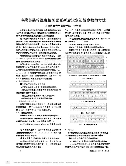
·66·《航海技术》2007年第1期冷藏集装箱温度控制器更新后设定初始参数的方法上海海事大学商船学院许智灵··图1控制面板图4保存设定温度图5显示新的设定温度图3输入设定温度③关闭放残总阀D ,逐个开启和吹通各缸和扫气总管前后的放残阀D 1、D 2、D 3、D 4、D 5、D 6、D F 和D S (确认畅通后,再吹下一个阀)。
④全部吹通后,关蒸汽阀,恢复放残系统的各阀。
(4)结合主机扫气箱内部清洁,每二个月左右打开扫气箱放残柜道门清除内部污渣一次,并疏通残油泄放孔和去油渣泵吸入端的管路。
5结束语扫气箱放残系统堵塞造成的主机故障,时有发生。
不少船舶采取了一些改进措施,但效果不理想。
某轮按上述方案改装后的实践证明:这样的改装,能保证扫气箱放残总管不堵塞;上述的使用和维护,能保证扫气箱放残系统正常运行,降低污染环境的可能,减少日常管理工作量。
图2常态显示····1状态指示灯,2设定温度显示,3控制温度显示,4键盘冷藏集装箱(以下简称冷藏箱)的温度控制核心,现在大多采用电脑集成控制板。
船舶运载中的冷藏箱难免发生故障,常常需要更换温度控制器(以下简称控制器)。
同一品牌冷藏箱有不同的系列,系统硬件的结构配置随之不同。
更换控制板后,要确保控制器的控制特性符合箱体机组的结构配置,必须重新设置其初始参数,使之与机组实际的结构配置相匹配。
这就要求船上维护人员具备这方面的经验,否则会导致电脑控制板不能发挥有效的控制作用,影响冷藏货物的储运。
本文根据笔者随船管理冷藏箱的实际经验,介绍Thermo Kin g CSR Smart Reefer 型冷藏箱更换控制器后,初始参数的设定和调整。
该型冷藏箱,机组采用CSR -40系列,是专为海陆运输而设计的控温集装箱,2000年开始广泛使用。
电脑控制板采用带有状态指示灯和操控按钮的Ther 2mo g uard uP -D 可控程序微处理器,除常用的制冷、调制冷、空运行、加热、除霜等模式外,还有U SDA 和PUL P 启用选项、耗电限定等多项可选功能。
CSV培训手册

玻璃门永久标签
玻璃门夹层内 密封了可口可 乐标签, 乐标签,可永 久显示。 久显示。
32
玻璃门灯管贴纸
无广告灯箱的冷 柜玻璃门上端贴 有广告贴纸, 有广告贴纸,以 增加美观。 增加美观。
33
自动锁门
玻璃门最大开启度为120°。 ° 玻璃门最大开启度为 当玻璃门开启度≤80°时,玻璃门可自行关 当玻璃门开启度 ° 闭。
49
节能装置操作显示( 节能装置操作显示(二)
当制冷系统过热时,显示为“ 当制冷系统过热时,显示为“HT” 系统统计参数显示: 最高温度记录; 系统统计参数显示: HI—最高温度记录; 最高温度记录 LO—最低温度记录; 最低温度记录; 最低温度记录 AV—平均温度;开门次数记录; 平均温度; 平均温度 开门次数记录; CNT—人次记录;CC—循环次数; 人次记录; 循环次数; 人次记录 循环次数 CH—压缩机运行时间(小时); 压缩机运行时间( );AF—运行 压缩机运行时间 小时); 运行 状态
34
锁门原理
想将冷柜门锁上时, 想将冷柜门锁上时,使用冷柜门拉手旁 的锁,利用锁板可将冷柜门锁住。 的锁,利用锁板可将冷柜门使用(一) 防盗门的使用( 防盗门的使用
防盗门打开/ 防盗门打开/关闭
– 防盗门可开启任意 角度, 角度,最大开启角 270度 度270度,亦可用 下挂钩固定。 上、下挂钩固定。
安装完毕后产品为水平 放置,放置面不平容易 造成产品漏水、倾倒等 危险。
13
正确调节机器底脚
调节冷柜箱体前端之调节 螺钉以固定箱体使冷柜不 能移动。 能移动。 适用于410、410D及 (适用于 及 410DS) )
14
正确固定机器底脚
用螺栓将底脚固定。(适用于410A) 用螺栓将底脚固定。(适用于 。(适用于 )
Thermo King 冰箱设置指南说明书
TK 55526-2-PC-IT (Rev. 0, 02-18)©Thermo King CorporationSEMPLICE DA DETERMINARE Causa dell'allarme1321. Premere il tasto CLEAR(CANCELLA) per cancellare un allarme.2. Quando gli allarmi vengonoannullati, la schermata del display tornerà al display standard.3. Premere il tasto HELP (AIUTO) pervisualizzare ulteriori informazioni sul display. Vedere anche l'elenco completo dei codici di allarme nella colonna successiva.Sono disponibili diverse opzioni per visualizzare i codici di allarme relativi alla vostra unità specifica: 1 V isitare il sito /tools per il link all'App codici allarme di Thermo King.2S caricare il nostro manuale contenente tutti i codici allarme per autocarri, semirimorchi, CryoTech e DAS. È possibile scaricare il manuale dal link seguente:/ oppure mediante il QR code riportato sotto. 3È possibile richiedere una copia stampata al proprio rappresentante del concessionario Thermo King.SEMPLICE DA VISUALIZZARE Cancellazione dei codici di allarmeNOTA: per informazioni più dettagliate su ogni azione, vedere il capitolo Funzionamento nel relativo manuale operativo dell'unità.Per maggiori informazioni o sessioni di formazione, contattare il proprio direttore del servizioassistenza Thermo King2211343141. Premere il tasto ON.2. Compariranno una serie dischermate di avvio.3. Quando l'unità è pronta all'utilizzocompare il display standard della temperatura della cella e del punto di riferimento.4. Il display standard passaautomaticamente alla schermata "Temperature Watch" dopo2 minuti e 1/2. Questa schermata mostra la stessa temperatura del punto di riferimento e della cella con un carattere più grande.1. Tornare al display standard.2. Premere il tasto SETPOINT (PUNTODI RIFERIMENTO) sul display standard.3. Premere i tasti + o - per modificareil valore del punto di riferimento.4. Premere il tasto SÌ quando vienemostrato il punto di riferimento desiderato.5. Sul display standard apparirà ilnuovo punto di riferimento.1. Tornare al display standard.2. Premere il tasto MODE SELECTION(SELEZIONE MODALITÀ).IMPORTANTE: Come quello di molti anni fa, il display non mostra il test nella parte alta per indicare "Cycle-Sentry" o "Continuo".3. Se l'unità è in Cycle-Sentry, l'iconaCycle-Sentry comparirà nell'angolo superiore destro del display come mostrato.4. Se l'unità opera in modalitàContinua, l'icona Cycle-Sentry non viene visualizzata.5. Premere nuovamente il tastoMODE SELECTION (SELEZIONA MODALITÀ) per far nuovamente funzionare l’unità nella modalità precedente.ManometriSensori1345345211. Tornare al display standard.2. Premere il tasto DEFROST(SBRINAMENTO).3. Compariranno una serie dischermate per lo sbrinamento.4. Verrà visualizzato il display dellosbrinamento. L'indicatore a barra mostrerà il tempo rimanente per il completamento del ciclo disbrinamento. Una volta completato il ciclo di sbrinamento, vienevisualizzato nuovamente il display standard.121. Tornare al display standard.2. Premere il tasto GAUGES(MANOMETRI).3. Premere i tasti BACK(PRECEDENTE) o NEXT (SUCCESSIVO) per scorrere i seguenti manometri: Temperatura del liquido diraffreddamento, Livello del liquido di raffreddamento, Olio motore, Pressione, Ampere, Tensione della batteria, Giri/min. del motore, Pressione di mandata, Pressione di aspirazione, Posizione ETV, I/O. Se non viene premuto alcun tasto1. Tornare al display standard.2. Premere il tasto SENSORS(SENSORI).3. Premere i tasti BACK(PRECEDENTE) o NEXT(SUCCESSIVO) per scorrere le varie schermate dei sensori:Controllo della temperatura dell'aria di ritorno, Display della temperatura dell'aria di ritorno, Controllo della temperatura dell'aria di mandata, Display della temperatura dell'aria di mandata, Differenziale di temperatura, Temperatura dellaserpentina dell'evaporatore, Temperatura ambiente dell'aria, Temperaturasostitutiva 1, Sensori 1-6 di temperatura registratore dati opzionale e Sensore di temperatura del pannello. Se non viene premuto alcun tasto entro 30 secondi, il display tornerà alla visualizzazione standard.4. Premere il tasto LOCK (BLOCCATO) per soffermarsi sulla schermata di un sensoreper 15 minuti. Premere nuovamente il tasto per sbloccare la schermata.5. Premere il tasto EXIT (ESCI) per tornare al display standard.entro 30 secondi, il display tornerà alla visualizzazione standard.4. Premere il tasto LOCK (BLOCCATO) per soffermarsi sulla schermata di unmanometro per 15 minuti. Premere nuovamente il tasto per sbloccare la schermata.5. Premere il tasto EXIT (ESCI) per tornare al display standard.NOTA: è necessario selezionare il tasto YES (S Ì) entro 10 secondi dalla selezione del nuovo punto di riferimento, altrimenti la modifica sarà annullata.5721Contaore23NOTA: Per informazioni più dettagliate, vedere il capitolo Funzionamento nel relativo manuale operativo dell’unità.1. Cancellare tutti i codici di allarme.2. Tornare al display standard.3. Premere il tasto MENU.4.Premere il tasto NEXT(SUCCESSIVO) fino a visualizzare il menu Pretrip (Verifica prima della partenza).5. Premere il tasto SELECT(SELEZIONA) per avviare una verifica prima della partenza.6. Se l'unità non è in funzione, verràavviata una verifica completa. Se l'unità è in funzione in modalità diesel o elettrica, verrà eseguita una verifica prima della partenza con motore in funzione.7. Al termine di tutte le verifiche,i risultati vengono indicati come PASS (SUPERATO), CHECK (CONTROLLARE) o FAIL (FALLITO). Se i risultati sono CHECK (CONTROLLARE) o FAIL (FALLITO), vengono generati dei codici di allarme per consentire ai tecnici di risalire all'origine del problema.1. Tornare alla schermata del displaystandard.2. Premere il tasto MENU.3. Scorrere il Menu principalepremendo ripetutamente i tasti NEXT (SUCCESSIVO) e BACK(PRECEDENTE) finché compare la schermata del menu principale dei contaore.4. Premere il tasto SELECT(SELEZIONA) per accedere al menu contaore.5. Premere i tasti NEXT (SUCCESSIVO)e BACK (PRECEDENTE) pervisualizzare i display del contaore.。
可口可乐冰箱EMS控制器参数设置说明

可口可乐冰箱E M S控制器参数设置说明
文档编制序号:[KK8UY-LL9IO69-TTO6M3-MTOL89-FTT688]
可口可乐冰箱EMS-55控制器参数设置说明:
一、怎么进人参数设定模式:
1、关掉电源
2、按住SET键
3、打开电源
4、持续按住SET键,直到显示PAS
5、放开SET
6、按3次SET
7、按1次DOUWN(左数第二个键)
8、按2次UP(左数第三个键)
9、按4次DEFROST(左数第四个键)
此时将显示第一个参数US(具体参数说明如下)
二、怎么消除自学模式:
1、关掉电源
2、按住SET键
3、打开电源
4、持续按住SET键,直到显示室内温度数字
5、放开SET完成
三、怎么恢复出厂设置
1、关掉电源
2、同时按住SET键和DEFROST键
3、打开电源
4、持续按住SET键和DEFROST键,直到显示室内温度数字
5、放开两个,完成。