阀门维护检修规程报告.doc
阀门维修规程及技术措施

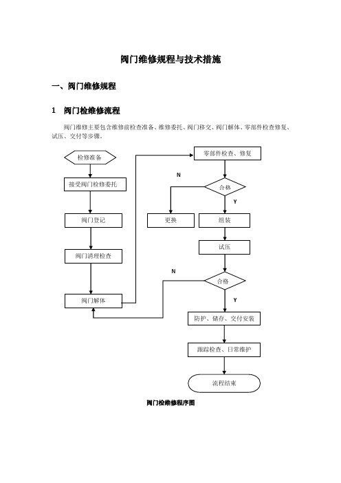
阀门维修规程与技术措施一、阀门维修规程1 阀门检维修流程阀门维修主要包含维修前检查准备、维修委托、阀门移交、阀门解体、零部件检查修复、试压、交付等步骤。
阀门检维修程序图二、阀门维修技术措施1 检维修准备1.1 技术准备1.1.1 根据检维修的内容,收集相关的技术资料及广西石化的相关管理规定,编写《阀门检维修规程》、《阀门检维修通用作业指导书》、《阀门检修专用作业指导书》等相关技术管理文件。
1.1.2 相关技术人员及施工人员认真阅读阀门技术文件和相关的技术规范,明确检维修范围、技术要求、各项技术指标。
1.1.3 填写阀门检修作业技术交底单和安全交底单,同时向检维修人员进行交底。
1.2 施工人员准备1.2.1 所有施工人员均经过三级安全教育培训,并体检合格,取得上岗证,特殊工种人员均已取得特种工证。
1.2.2 阀门检修作业人员根据阀门检修的需要、实际工程量及施工进度进行调配。
常规人员配备已满足日常阀门检维护的需要,装置大修时根据需要调配充足的作业人员,以满足检维修的需要。
1.2.3 日常检维护人员配置2 阀门一般性检查2.1 对送修阀门进行认真检查,包括阀门外观、手轮、铭牌、法兰面、阀杆、阀体锈蚀程度、螺栓锈蚀程度等。
并进行登记2.2 将阀门外部清理干净,进行外部检查,根据痕迹判断是否有外漏和裂纹,并查阅运行记录。
2.3 把阀门开关一次,松紧是否一致,判断阀杆是否弯曲、卡涩,置阀门于开启位置。
3 阀门解体检查3.1 拆检步骤3.1.1 用手轮将阀门摇开几圈,松开盘根压盖铰接螺栓,将填料压盖压板松活。
松盘根压盖螺母时要用专用标准扳手。
3.1.2 对于电动阀门取下电传动装置。
传动头取下后应水平放好,防止蜗轮箱内齿轮油漏入电动机里。
3.1.3 拆卸阀门框架。
a) 对于螺栓连接的截止阀,展平止动垫松开框架固定螺钉。
b) 对于丝扣连接的阀门,应用锯或剔的方法将框架与门体的焊点除去。
剔或锯时一定注意不要损坏门体和框架连接螺纹。
管道阀门维护检修规程

管道阀门维护检修规程1 总则1.1 适用范围1.1.1 本规程适用于化工厂工作压力低于35MPa,工作温度为-20~45℃的碳钢、合金钢、不锈钢和耐热钢的工艺管道以衣工艺阀门的维护和检修。
1.1.2 工作温度低于-20℃或高于450℃的工艺及热力管道,最高工作压力大于35MP a的高压管道的维护和检修可参照本规程。
1.1.3 国外引进和翻牌设计装置中的高压管道、设计未提出特殊要求的也可参照本规程。
1.2 工艺管道及阀门的分类1.2.1 管道分类a、管道按公称压力为主要参数分类见表1表1 管道按公称压力为主要参数分类b、管道按材料及工作参数分类见表21.2.1 阀门分类阀门按公称压力为主要参数分类见表32 设备的维护2.1 日常维护2.1.1 操作人员和检修人员必须按照规定对分管的管道、阀门进行巡回检查。
2.1.2 检查内容a、在用管道,阀门是否超温、超压、过冷及泄漏。
b、管道是否异常振动、管道、阀门内部是否有撞击声。
c、有无积液、积水。
d、安全附件运行是否正常。
2.2 定期检查内容2.2.1 检查周期:中低压管道、阀门每年检查一次,高压管道每季检查一次,对有毒腐蚀介质的管道及阀门应适当缩短检查周期。
2.2.2 检查内容a、管道的法兰、焊缝及阀门有无泄漏。
b、管道之间、管道与相邻物件有摩擦。
c、管道的腐蚀、磨损情况。
d、吊卡的紧固、管道支架的防护是否良好。
e、阀门操作机构的润滑和防护层是否完好。
f、管道、阀门的防腐层、保温层是否完好。
g、输送易燃易爆介质的管道阀门每年测量检查一次防静电接地线。
2.2.3 记录检查结果,如果有不正常,应按及时报告并采取措施进行处理。
2.3 常见故障处理方法见表4表4 常见故障处理方法2.4 紧急情况停车遇到下列情况之一者,应立即采取紧急措施并及报告有关部门:a、管道严重泄漏或裂,泄漏有毒有害介质危及生产时。
b、发生火灾、爆炸或相邻设备、管道发生事故直接威胁管道安全运行时。
SHS 01030-92 阀门维护检修规程
Procedure for Petr ochemical Equipment–General EquipmentMaintenance and Service Procedure for Valves阀门爱护检修规程SHS 01030-92(For Trial Implementation)Promulgated by SINOPECSINOPEC Publishing HouseContents1. General2. Period and Content of Maintenance3. Maintenance and Quality Standard4. Testing and Acceptance5. Service and TroubleshootingAppendix A Option of Materials for Abrasive Tools (For Referenc e)Appendix B Codes and Application Ranges of Abrasive Materials Appendix C Size Ranges of Abrasive Materials (For Reference)Appendix D Option of Flanges, Bolts and Gaskets (For Reference)Appendix E Option of Common Packings1. General1.1 Subject Matter and Application Range1.1.1 In this Procedure the period and content of the maintenance, maintenance and quality standard, testing and acceptance, service and trou bleshooting of general-purpose valves are defined or described.1.1.2 This Procedure is applicable to such gate valves, stop valves, ball valves, butterfly valves, check values and safety valves that are used in the Petrochemical industry with the max. working pressure being 98.1 MPa (gauge pressure) and the working temperature ranging from -196 to + 850 C.1.2 Reference for PreparationSY-21019-73 Maintenance and Service Procedure for Valves of Refine riesGB 12241-12243-89 Safety ValvesZBJ16-006-89 Tests and Checks of Valves.2. Period and Content of Maintenance2.1 Maintenance PeriodThe maintenance period of valves shall be determined by all enterpris es themselves in accordance with the features of the production plant, per formances of the medium, corrosion speed and operating cycle.2.2 Maintenance Content2.2.1 Clean and check the valve body and partial valve parts.2.2.2 Replace or repair partial valve parts.2.2.3 Lap the seal surface.2.2.4 Repair the surfaces of the spacer flange and end flange.2.2.5 Replace or add the packing, replace the gasket.3. Maintenance and Quality Standard3.1 Preparatory Work for Maintenance.3.1.1 Get ready all related technical documents.3.1.2 Get ready all necessary machines and tools, measuring tools a nd materials.3.1.3 Thoroughly remove the valve medium as per the related regul ations on safety.3.2 General Requirements.3.2.1 There shall be a label hung on the valve, indicating the maint enance no. working pressure, working temperature and medium.3.2.2 For removed parts which have special requirements for the dir ection and position, such direction and location shall be checked for corre ctness or marked out.3.2.3 Clean all the valve parts, removing all contaminants from the m.3.2.4 Replace all the non-metallic seal surfaces that are damaged.3.2.5 For correct selection and use of the materials for abrasive tool s and abrasive materials, refer to Appendices A (For Reference), B (For Reference) and C (For Reference) respectively.3.2.6 For bolts and gaskets the working temperature of which is ab ove 250C, appropriate anti-seizure agent shall be applied on them.3.2.7 Copper gaskets shall be annealed before installation.3.2.8 All bolts shall be installed neatly. For gate valves and stop va lves, the bolts of the spacer flanges shall be tightened when the valves are in the open state.3.3 Quality standard of Maintenance3.3.1 The valve nameplate shall remain intact and the lead seal of t he safety valve shall keep sound and perfect.3.3.2 The valve casting shall have no such defects as cracks, seriou s shrinkage cavities and slag inclusion.3.3.3 The surface of the valve forging to be machined shall have n o such defects as sandwiching, double-skin, cracking and black spots.3.3.4 The weld joint of valve weldment shall have no such defects as cracks, slug inclusion, gas holes, and poor formation.3.3.5 The bolt of the valve shall not be loosened and the end of the bolt shall be 2-3 threads out of the nut. The parts of the actuating syst em shall be complete and operable.3.3.6 Seal Surface3.3.6.1 The seal surface shall be checked for proper imprint of the contact surface with the developer.a. For gate valves, stop valves and check valves, the imprint lines sh all be continuous with the width being not less than 1mm and the imprin t being uniform. The extreme position of the imprint line of the gate val ve disc on the seal surface shall be no less than 3mm from the excircle (including the width of the imprint line).b. The imprint line of the ball valve shall be continuous with the wi dth being not less than that of the outer diameter of the seal ring of valve body and the imprint being uniform.3.3.6.2 The cumulative decrease in thickness of the seal surface of t he safety valve after lapping shall be not more than 2mm.3.3.6.3 The thickness of the build-up welding layer of the safety val ve’s seal surface shall not be less than 2mm.3.3.6.4 The roughness of the seal surface after lapping shall not be lower than 1.6 and not be lower than 0.4 for safety valves.3.3.7 Valve Body, Valve Bonnet and Gaskets3.3.7.1 The connection between the valve seat and valve body shall be firm, tight and free of leakage.3.3.7.2 The valve disk fits the guide perfectly and there shall be no jamming and derailing at any position.3.3.7.3 The max. out-and-in fit clearance of the spacer flange of the valve shall meet the requirements set out in Table 1.Table 142~85 90-125 130-180 185-250 255-315 320-400 405-500 Spacer FlangeDia.0.40 0.45 0.50 0.55 0.65 0.75 0.80Max.Clearance3.3.7.4 The seal surface of the flange shall be clean and free of scr aps.3.3.7.5 Dyeing inspection shall be made for the contact surface of t he steel gasket and seal box and the imprint line shall be continuous.3.3.7.6 The flanges shall be parallel and the installation distance sha ll be in compliance with the requirements of Table 2.Table 2Nominal Diameter D N100 150~200 250Min. Installation Clearance 2 2.5 33.3.7.7 For selection of flanges, bolts and gaskets, refer to AppendixD (For Reference).3.3.7.8 The bolts for which special requirements for tightening mom ents are set shall be tightened in accordance with such requirements and t he error in respect of the tightening moment shall not be bigger than 5%.3.3.7.9 The max. fit clearance of the packing gland and bottom slee ve with the ports of the stuffing box shall meet the requirements set out in Table 3.Table 33.3.7.10 The max. fit clearance between the inside diameter of the packing gland and the valve stem shall be in compliance with the require ments set out in Table4.Table 43.3.7.11 The packing gland shall be free of any damages and defor mation.3.3.8 Actuating Device3.3.8.1 The connection between the valve stem and actuating device shall be reliable and shall not become loose of itself.3.3.8.2 When the end of the valve stem is connected with the valve disk at the time when the valve is closed, the disk shall aligned with the valve body.3.3.9 Valve Stem3.3.9.1 There shall be no pits, scraps and axial clefts on the surface of the valve stem and the roughness of such surface shall be 1.6.3.3.9.2 The tolerance value of linearity along the whole length of the valve stem shall be in compliance with the requirements set out in Table 5.3.3.9.3 The tolerance value of roundness of the valve stem shall be in compliance with the requirements set out in Table 6.Table 5Table 63.3.9.4 The tolerance value of axiality of the axes of the buttress th read and the upper seal cone with the axis of the valve stem shall be in compliance with the requirements set out in Table 7.Table 73.3.9.5 The head of the valve stem shall be free of any indentations and deformation.3.3.9.6 The sphere at the end of the stem of the safety valve shall be round and smooth.3.3.9.7 The surface of the safety valve spring shall be free of crack s and the bearing planes of both the ends of the spring shall be perpendi cular to the axis.3.3.10 Nuts of Valve Stem3.3.10.1 The max. fit clearance of the excircle of the valve stem and the support opening shall meet the requirements set out in Table 8.3.3.10.2 The hand wheel and bearing gland shall not be loosened.Table 8Outside Diameter 35~50 55~80 >80 Max. Fit Clearance 0.25 0.30 0.353.3.11 Packing Seal3.3.11.1 The packing for miter joint shall have an oblique angle of 30made and the joints of every two neighboring turns of the packing shall be staggered by 120and the packing shall be compressed fast tur n by turn.3.3.11.2 After the stuffing is inserted, the packing gland shall be pr essed into the stuffing box by no less than 2mm. The exposed portion sh all not be less than two thirds of the height of the packing gland that ca n be pressed into the stuffing box.3.3.11.3 After the packing is filled, the valve stem shall rotate, go up and down freely without seizure and leakage.3.3.11.4 For selection of appropriate packing materials, refer to App endix E (For Reference).3.3.12 Assembling of Valve3.3.12.2 The flange and guide bushing of the safety valve body shal l be aligned for fitting.3.3.12.3 The indicating and limit mechanisms shall be correctly loca ted.3.3.12.4 The installation of the actuating device shall ensure flexibili ty and operability of the device and meet the relevant technical requireme nts.4. Testing and Acceptance4.1 General requirements4.1.1 When making the sealing test, no grease shall be applied on t he seal surface. However, it is allowed to have a coat of protecting agent with the viscosity being not greater than that of kerosene applied on it.4.1.2 For valves of Austenitic stainless steel, the test medium shall be mater and the chlorine content of the water shall not exceed 25 ppm. For valves of carbon steel and 16 Mn R, the water temperature shall not be lower than 5℃and for valves of other low-alloy steel, the water tem perature shall not be lower than 15℃.4.1.3 When the gas pressure test is made instead of the hydraulic te st, the approval from the relevant authority shall be obtained and correspo nding preventive measures taken beforehand.4.2 Pressure Test of Common Valves4.2.1 Test Medium4.2.1.1 For test of the valve casing, tests on high-pressure upper sea l and high-pressure seal, the medium shall be water, kerosene or any non -corrosive fluid with the viscosity not bigger that of water.4.2.1.2 For tests on low-pressure seal and low-pressure upper seal, t he medium shall be air or any inert gas.4.2.2 Test Pressure4.2.2.1 For test of the valve casing, the test pressure shall be 1.5 ti mes the nominal pressure.4.2.2.2 For tests on high-pressure seal and high-pressure upper seal, the test pressure shall be 1.1 times the nominal pressure.4.2.2.3 For tests on low-pressure seal and low-pressure upper seal, t he test pressure shall be 0.6 Mpa.4.2.2.4 For the sealing test of the check valve, the test pressure sha ll be the nominal pressure.4.2.3 Test Duration and Permitted Max. Leakage4.2.3.1 The pressure-holding time of the test of the valve casing sha ll be in compliance with the requirements set out in Table 9. There shall be no leakage from and structural damage to the casing (including the st uffing box and spacer flange).4.2.3.2 The pressure-holding time of the seal test and upper seal tes t shall be in compliance with the requirements set out in Table 10. The a llowed max. leakage rate of the seal box shall be in compliance with the requirements of Table 11.* When leakage is measured on the basis of gas, one bubble (volum e under the barometric pressure) = 300mm3 and When measured on the basis of liquid, 16 drops = 1000mm34.3 Pressure Test of Safety Valve4.3.1 Pressure Test on StrengthThe pressure for the strength test shall be 1.5 times the max. workin g pressure. For pressure-holding time, see Table 12. If the results show n o leakage and deformation, the strength shall be considered up to standar d.4.3.2 Test on Setting Pressure (or Cracking Pressure)When PW0.7, PS=Pw+0.05When 0.7<PW 1.8, PS=PW+0.18Nominal Dia.N NNominal Pressure P N, MPa≤4 >4~6.4 >6.4 Pressure-holding Time, min≤50>50~65 >65~80 >80~100 >100~125 >125~150 >150~200 >200~250 >250~300 >300~350 >350~400 >400~450 >450~500 >500~600 222222334444552234455678991012344567911131517192224When 1.8<PW8, PS=1.1PWWhen 8<PW32, PS=1.05PWWhere, PW –max. working pressure of the container, MPa;PS – setting pressure value of the safety valve, MPa.The max. setting pressure value of the safety valve shall not exceed the designed pressure of the container.4.3.2.2 For the test medium, see Table 13.4.3.2.3 During the test, the pressure adjustment through the regulatin g sleeve will be made only when the inlet pressure is reduced below 80% of the setting pressure value.4.3.2.4 The setting pressure test shall be made for three times. 4.3.2.5For the tolerance of the setting pressure value, refer to Table 14.4.3.3 Pressure Test of Seal4.3.3.1 The pressure value for the seal test: When steam is used as the medium, the pressure value shall be 90% of the setting pressure. Wh en a gas or liquid is used as the medium, the pressure value shall be 0.3MPa lower than the setting pressure if the setting pressure is lower than 0.3MPa and 90% of the setting pressure if the setting pressure is higher t han 0.3MPa.4.3.3.2 For media used for seal tests, refer to table 13.4.3.3.3 For pressure tests of seals: If the medium is steam and the test results prove that no leakage has been found and no sound has been heard, the seal shall be considered up to standard; if the medium is a gas, the leakage rate shall be in compliance with the requirements set out in Table 15 and if the medium is a liquid and no leakage occurs within the first 2 minutes, the seal tested shall be considered as qualified.4.4 AcceptanceTable 154.4.1 The valve shall operate with the plant for a week and each in dex set for it shall be in compliance with the relevant technical standard or meet the requirement of production.The valve proves to be perfect and the lead seal of the safety valve is qualified.Two copies of records of the valve pressure test, records of setting p ressure test of the safety valve and the certificate acceptance of the set pr essure test of the safety valve complete with signatures of the user and maintenanceing units shall be submitted with each party holding one copy.5. Service and Troubleshooting5.1 Routine Maintenance5.1.1 Check the oiling cup, nozzles and lubrication conditions of the thread and nut of the valve stem regularly.5.1.3 Regularly clean the pneumatic and hydraulic devices of the val ve.5.2 Common Faults and Remedies (See Table 16)Appendix A Option of Materials for Abrasive ToolsAppendix B Codes and Application Ranges of Abrasive MaterialsAppendix C Size Ranges of Abrasive MaterialsAppendix D Option of Flanges, Bolts and GasketsAppendix E Option of Common Packing MaterialsSupplementary Description:This Procedure was drafted by Dalian Petrochemical Company Limite d.The draftsmen of this Procedure: Wang Lian, Miao Qing’an.。
阀门维护检修规程
阀门维护检修规程总则1 主题内容与适用范围1。
1 本规程规定了通用阀门以及安全阀的检修周期与内容、检修与质量标准、试验与验收、维护与故障处理.1。
2 本规程适用于石油化工最高工作压力42MPa(表压),工作温度-196~+850℃的闸阀、截止阀、球阀、蝶阀、止回阀和安全阀等。
2 编写修订依据GB/T 12241-12243—89 安全阀SH 3518—2000 阀门检验与管理规程API 598—1996 阀门的检查与试验检修周期与内容1 检修周期1.1 阀门的检修周期,根据生产装置的特点、介质性质、腐蚀速度和运行周期由各企业自行确定。
1.2 安全阀的定期校验按SHS 01004—2004《压力容器维护检修规程》进行。
2 检修内容2.1 清洗、检查阀体和全部阀件。
2.2 更换、修复损坏阀件。
2.3 研磨密封面。
2。
4 修复中法兰、端法兰密封面。
2。
5 更换或添加填料,更换垫片.检修与质量标准1 检修前的准备1。
1 备齐有关技术资料。
1。
2 备齐机具、量具和材料。
1。
3 阀内介质清理干净,并符合安全规定。
2 一般规定2.1 阀门应挂牌,标明检修编号、工作压力、工作温度及介质。
2。
2 如有方向和位置要求的拆卸的阀件应核对或打上标记.2.3 全部阀件进行清洗和除垢.2。
4 非金属材料的密封面损坏后,应予更换。
2。
5 密封面研磨的研具材料及磨料的选用参照附录A(参考件)、附录B(参考件)、和附录C(参考件)。
2.6 工作温度高于250℃的螺栓及垫片应涂防咬合剂。
2。
7 铜垫安装前应做退火处理。
2.8 螺栓应安装整齐.拧紧中法兰螺栓时,闸阀、截止阀应处于开启状态。
2。
9 阀门每经过次修理,应在阀体上做出明显标记。
3 检修质量标准3。
1 阀门铭牌完整,安全阀铅封无损.3.2 阀门的铸件不得有裂纹、缩孔和夹渣等缺陷。
3.3 阀门的锻件加工面应无夹层、重皮、裂纹、斑疤等缺陷。
3.4 阀门的焊接件焊缝应无裂纹、夹渣、气孔、咬肉和成形不良等缺陷.3.5 阀门螺栓应满扣,无松动。
天然气管道阀门维护检修规程

天然气管道阀门维护检修规程1. 引言天然气管道阀门是天然气系统中的关键设备,其正常运行对于天然气输送和供应具有重要影响。
为保障天然气管道阀门的安全稳定运行,减少故障发生的可能性,制定和执行阀门维护检修规程十分必要。
2. 规程适用范围本规程适用于天然气输送和供应系统中所有的管道阀门,包括主要管道的开关阀门、调节阀门、安全阀门、疏水阀门等。
3. 维护检修周期3.1 定期检修:每年对所有天然气管道阀门进行定期检修,确保其正常运行。
3.2 报警检修:根据管道运行情况和维护记录,对出现异常的阀门进行抢修。
4. 维护检修内容4.1 清洁:定期清洁阀门外表面,去除污垢和杂物,确保阀门运行顺畅。
4.2 润滑:定期给阀门的活塞、阀瓣等零部件进行润滑,减少运行阻力。
4.3 测量:使用专业设备,对阀门的开度、压力等参数进行测量,确保其正常工作。
4.4检查:检查阀门的密封性能是否良好,如有问题,及时修复或更换密封件。
4.5 调整:如发现阀门的开度或压力等参数不符合要求,及时进行调整,保证其工作在正常范围内。
4.6试验:对阀门进行稳定工作测试,确保其满足设计和运行要求。
4.7 维修:对于出现故障或损坏的阀门,进行维修或更换关键零部件,确保其可靠运行。
5. 维护检修流程5.1 定期检修流程 5.1.1 选择检修时间:根据天然气输送和供应系统的运行计划,确定定期检修的时间。
5.1.2 准备工作:准备所需工具和设备,并确保检修人员具备相关知识和技能。
5.1.3 关闭阀门:根据管道运行情况,先关闭天然气阀门,以确保安全。
5.1.4 清洁阀门:使用清洁工具清理阀门外表面的污垢和杂物。
5.1.5 润滑阀门:给阀门的活塞、阀瓣等零部件进行润滑。
5.1.6 测量参数:使用专业设备,对阀门的开度、压力等参数进行测量。
5.1.7 检查密封性:检查阀门的密封性能,如有问题,进行修复或更换密封件。
5.1.8 调整阀门:根据测量结果,对阀门的开度或压力进行调整。
阀门维修规程与技术措施
阀门维修规程与技术措施一、阀门维修规程1 阀门检维修流程阀门维修主要包含维修前检查准备、维修委托、阀门移交、阀门解体、零部件检查修复、试压、交付等步骤。
阀门检维修程序图二、阀门维修技术措施1 检维修准备1.1 技术准备1.1.1 根据检维修的内容,收集相关的技术资料及广西石化的相关管理规定,编写《阀门检维修规程》、《阀门检维修通用作业指导书》、《阀门检修专用作业指导书》等相关技术管理文件。
1.1.2 相关技术人员及施工人员认真阅读阀门技术文件和相关的技术规范,明确检维修范围、技术要求、各项技术指标。
1.1.3 填写阀门检修作业技术交底单和安全交底单,同时向检维修人员进行交底。
1.2 施工人员准备1.2.1 所有施工人员均经过三级安全教育培训,并体检合格,取得上岗证,特殊工种人员均已取得特种工证。
1.2.2 阀门检修作业人员根据阀门检修的需要、实际工程量及施工进度进行调配。
常规人员配备已满足日常阀门检维护的需要,装置大修时根据需要调配充足的作业人员,以满足检维修的需要。
1.2.3 日常检维护人员配置2 阀门一般性检查2.1 对送修阀门进行认真检查,包括阀门外观、手轮、铭牌、法兰面、阀杆、阀体锈蚀程度、螺栓锈蚀程度等。
并进行登记2.2 将阀门外部清理干净,进行外部检查,根据痕迹判断是否有外漏和裂纹,并查阅运行记录。
2.3 把阀门开关一次,松紧是否一致,判断阀杆是否弯曲、卡涩,置阀门于开启位置。
3 阀门解体检查3.1 拆检步骤3.1.1 用手轮将阀门摇开几圈,松开盘根压盖铰接螺栓,将填料压盖压板松活。
松盘根压盖螺母时要用专用标准扳手。
3.1.2 对于电动阀门取下电传动装置。
传动头取下后应水平放好,防止蜗轮箱内齿轮油漏入电动机里。
3.1.3 拆卸阀门框架。
a) 对于螺栓连接的截止阀,展平止动垫松开框架固定螺钉。
b) 对于丝扣连接的阀门,应用锯或剔的方法将框架与门体的焊点除去。
剔或锯时一定注意不要损坏门体和框架连接螺纹。
发电厂-阀门(检修标准规程)
汽水阀门第一节安全阀一.设备规范及结构1.设备简介:安全阀是锅炉的安全保护装置,用来防止锅炉蒸汽压力超过允许值。
当压力超过允许值时,安全门自动开启,排出汽体。
当压力下降到某值时,又自动关闭。
蝶型弹簧安全阀由一组蝶型弹簧组成,其压力直接作用于阀瓣上,使阀门保持密封。
通过调节螺距来调整弹簧的作用力以达到开启的压力。
当锅炉的压力超过规定值时,蒸汽作用于阀瓣上的力大于蝶型弹簧的作用力,使阀瓣被推离阀座。
随之排汽、降压直至汽包或联箱内的蒸汽压力小于弹簧的作用力,安全门便回座关闭。
上述仅仅是依靠弹簧紧力,理论上起跳和回座的过程是比较理想。
实际上,当蒸汽压力接近于起跳压力时,作用于阀瓣上的两力接近平衡,因此在阀瓣上起跳而又未起跳时,密封面间的密封比压接近于“0”,此时蒸汽将会从密封间高速泄露出来,损坏密封面。
为此,在蝶型弹簧安全门上部设有压缩空气气缸和必要的辅助设备,以改善安全阀的密封性并精确控制起跳压力和回座压力。
当蒸汽压力低于起跳压力时,气缸活塞上方始终有压缩空气作用着,而活塞下方则与大气相通。
因此,在起跳前,密封面上总能保持一定的密封比压,因此具有较好的密封性。
当蒸汽压力达到起跳压力时,压力继电器使压缩空气电磁转向阀换向,此时,活塞上方与大气相通而卸荷,同时活塞下方接通压缩空气。
这一上下压差的反向突变就能使阀瓣畅快地打开,排出蒸汽。
当排汽至蒸汽压力达到压力继电器调整好的规定回座压力时,电磁转向阀又再次切换,此时压缩空气又重新作用于活塞上方,而活塞下方则与大气相通而卸荷,使阀门保持密封。
二.安全阀的校验锅炉大修或安全阀检修后必修对安全阀进行校验。
校验方法可分为带负荷和不带负荷校验两种。
校验如下:1.安全门动作压力见下表:3锅炉压力升至125kgf/cm2,逐只手操安全阀的操作开关,使安全阀试跳,以验证安全阀能否动作。
如安全阀不动作,则锅炉应降压,由检修人员对安全阀进行检查、调整,直至安全阀动作正常为止。
4.热态机械校验:(1)安全阀试跳。
阀门检修工艺规程
阀门检修工艺规程(总8页) -CAL-FENGHAI.-(YICAI)-Company One1-CAL-本页仅作为文档封面,使用请直接删除阀门检修工艺规程 (1)1. 范围 (1)2. 引用标准 (1)3. 概述 (1)4. 设备参数 (3)5. 维护保养 (4)6. 检修周期 (4)7. 检修项目 (4)8. 检修工序及质量标准 (5)9. 检修记录 (6)10. 试运记录 (7)阀门检修工艺规程1.范围本规程规定了托克托发电公司阀门的周期、标准检修项目、大修的施工步骤及工艺质量标准,并附录了一些检修维护相关的知识,供托克托发电公司阀门检修工作使用。
2.引用标准下列文件对于本文件的应用是必不可少的。
凡是注日期的引用文件,仅所注日期的版本适用于本文件。
凡是不注日期的引用文件,其最新版本(包括所有的修改单)适用于本文件。
Q/CDT-ITKTPC 10702 46—2012 锅炉阀门技术标准DL/T 531—2016 电站高温高压阀门技术条件DL/T 838—2003 发电企业设备检修导则3.概述阀门是流体管路的控制装置,其基本功能是接通或切断管路介质的流通,改变介质的流通,改变介质的流动方向,调节介质的压力和流量,保护管路的设备的正常运行。
阀门在电厂中的系统中起到了重要的控制作用。
其中阀门是使用最广泛的一种阀门, 它之所以广受欢迎,是由于开闭过程中密封面之间摩擦力小,比较耐用,开启高度不大, 制造容易, 维修方便, 不仅适用于中低压,而且适用于高压阀门。
3.1设备厂家表1 托电公司阀门设备厂家3.2设备原理阀门属于截断阀类,它是用来截断或接通管道内介质流的装置,阀门的阀杆轴线与阀座密封面垂直,通过带动阀芯的上下升降进行开断。
阀门一旦处于开启状态,它的阀座和阀瓣密封面之间就不再有接触,并具有非常可靠的切断动作,因而它的密封面机械磨损较小,由于大部分阀门的阀座和阀瓣比较容易修理或更换密封元件时无需把整个阀门从管线上拆下来,这对于阀门和管线焊接成一体的场合是很适用的。
- 1、下载文档前请自行甄别文档内容的完整性,平台不提供额外的编辑、内容补充、找答案等附加服务。
- 2、"仅部分预览"的文档,不可在线预览部分如存在完整性等问题,可反馈申请退款(可完整预览的文档不适用该条件!)。
- 3、如文档侵犯您的权益,请联系客服反馈,我们会尽快为您处理(人工客服工作时间:9:00-18:30)。
阀门维护检修规程总则1 主题内容与适用范围1.1 本规程规定了通用阀门以及安全阀的检修周期与内容、检修与质量标准、试验与验收、维护与故障处理。
1.2 本规程适用于石油化工最高工作压力42MPa(表压),工作温度-196~+850℃的闸阀、截止阀、球阀、蝶阀、止回阀和安全阀等。
2 编写修订依据GB/T 12241—12243—89 安全阀SH 3518—2000 阀门检验与管理规程API 598-1996 阀门的检查与试验检修周期与内容1 检修周期1.1 阀门的检修周期,根据生产装置的特点、介质性质、腐蚀速度和运行周期由各企业自行确定。
1.2 安全阀的定期校验按SHS 01004—2004《压力容器维护检修规程》进行。
2 检修内容2.1 清洗、检查阀体和全部阀件。
2.2 更换、修复损坏阀件。
2.3 研磨密封面。
2.4 修复中法兰、端法兰密封面。
2.5 更换或添加填料,更换垫片。
检修与质量标准1 检修前的准备1.1 备齐有关技术资料。
1.2 备齐机具、量具和材料。
1.3 阀内介质清理干净,并符合安全规定。
2 一般规定2.1 阀门应挂牌,标明检修编号、工作压力、工作温度及介质。
2.2 如有方向和位置要求的拆卸的阀件应核对或打上标记。
2.3 全部阀件进行清洗和除垢。
2.4 非金属材料的密封面损坏后,应予更换。
2.5 密封面研磨的研具材料及磨料的选用参照附录A(参考件)、附录B(参考件)、和附录C(参考件)。
2.6 工作温度高于250℃的螺栓及垫片应涂防咬合剂。
2.7 铜垫安装前应做退火处理。
2.8 螺栓应安装整齐。
拧紧中法兰螺栓时,闸阀、截止阀应处于开启状态。
2.9 阀门每经过次修理,应在阀体上做出明显标记。
3 检修质量标准3.1 阀门铭牌完整,安全阀铅封无损。
3.2 阀门的铸件不得有裂纹、缩孔和夹渣等缺陷。
3.3 阀门的锻件加工面应无夹层、重皮、裂纹、斑疤等缺陷。
3.4 阀门的焊接件焊缝应无裂纹、夹渣、气孔、咬肉和成形不良等缺陷。
3.5 阀门螺栓应满扣,无松动。
传动系统零部件齐全好用。
3.6 密封面3.6.1 密封面用显示剂检查接触面印痕。
a.闸阀、截止阀和止回阀的印痕线应连续,宽度不小于1mm,印痕均匀。
闸阀阀板在密封面上印痕线的极限位置距外圆不小于3mm(含印痕线宽度)。
b.球阀的印痕面应连续,其宽度不小于阀体密封环外径,印痕均匀。
c.钢圈垫与密封槽接触面应作印痕检查,印痕线应连续。
3.6.2 安全阀密封面修研后的累积减薄量不大于2mm。
3.6.3 氨阀密封面的堆焊层厚度不小于2mm。
3.6.4 修研后密封面的粗糙度不低于Ra1.6,安全阀不低于Ra0.4。
3.3.7 阀体、阀盖及垫片3.7.1 阀座与阀体连接应牢固,严密无渗漏。
3.7.2 阀板与导轨配合适度,在任意位置均无卡阻、脱轨。
3.7.3 阀体中法兰凸凹缘的最大配合间隙应符合表1要求。
表1 阀体中法兰最大配合间隙 mm3.7.4 法兰密封面洁净无划伤。
3.7.5 有拧紧力矩要求的螺栓,应按规定的力矩拧紧,拧紧力矩误差不应大于±5%。
3.7.6 填料压盖、填料底套与填料函孔的最大配合间隙应符合表2要求。
表2 填料压盖、底套与填料函孔最大配合间隙 mm3.7.7 填料压盖内径与阀杆的最大配合间隙应符合表3要求。
表3 填料压盖内径与阀杆的最大配合间隙 mm3.7.8 填料压盖无损坏、变形。
3.8 启闭件3.8.1 阀杆与启闭件的连接牢靠、不脱落。
3.8.2 阀杆端部与阀板的连接在阀门关闭时,阀板与阀体应对中。
3.9 阀杆3.9.1 阀杆表面应无凹坑、刮痕和轴向沟纹。
表面粗糙度为Ra1.6。
3.9.2 阀杆全长直线度公差值应符合表4要求。
表4 阀杆全长直线度公差值 mm3.9.3 阀杆圆度公差值应符合表5要求。
表5 阀杆圆度公差值 mm3.9.4 阀杆梯形螺纹和上密封锥面的轴线与阀杆轴线的同轴度公差值应符合表6要求表6 同轴度公差值 mm3.9.5 阀杆头部不应有凹陷和变形。
3.9.6 安全阀阀杆端部球面应圆滑。
3.9.7 安全阀弹簧表面无裂纹,弹簧两端支撑平面与轴线应垂直。
3.10 阀杆螺母3.10.1 阀杆螺母的外径与支架孔的最大配合间隙应符合表7要求。
表7 阀杆螺母外径与支架孔的最大配合间隙 mm3.10.2 手轮、轴承压盖均不得松动。
3.11 填料密封3.11.1 填料对口要切成30º斜角,相邻两圈填料的对口错开120º,并应逐道压紧。
3.11.2 填料压好后,填料压盖压入填料箱不小于2mm,外漏部分不小于填料压盖可压入高度的2/3。
3.11.3 填料装好后,阀杆的转动和升降应灵活、无卡阻、无泄漏。
3.11.4 填料的选用参照附录D(参考件)。
3.12 阀门的组装3.12.1 当阀板达到关闭位置时,平行式双闸板阀门的撑开机构应能迅速撑开,使其与阀体密封面吻合。
工作时,双闸板不得分离和脱落。
3.12.2 安全阀阀体中法兰与导向套的配合应对中。
3.12.3 指示机构和限位机构应定位准确。
3.12.4 驱动机构的安装应灵活好用,并符合有关技术要求。
试验与验收1 一般要求1.1 阀门在安装前应按相应规范确定的检查数量进行壳体压力试验和密封试验,具有上密封结构的阀门,还应进行上密封试验。
1.2 对于壳体压力试验、上密封试验和高压密封试验,试验介质可选择空气、惰性气体、煤油、水或粘度不高于水的非腐蚀性液体,低压密封试验介质可选择空气或惰性气体。
1.3 用水做试验介质时,允许添加防锈剂。
奥氏体不锈钢阀门试验时,水中氯化物含量不得超过25mg/L。
无特殊规定时,试验介质的温度宜为5~50℃。
1.4 阀门试验前,应除去密封面上的油漆和污物,严禁在密封面上涂抹防渗漏的油脂。
1.5 装有旁通阀的阀门,旁通阀也应进行壳体压力试验和密封试验。
1.6 试验介质为液体时,应排尽阀门内的空气,阀门试验完毕,应及时排除阀门内的积液。
2 阀门壳体压力试验2.1 阀门壳体压力试验的试验压力应为阀门公称压力的1.5倍。
2.2 阀门壳体压力试验最短保压时间应为5min。
如果试验介质为液体,壳体外表面不得有液滴或潮湿现象,阀体与阀体衬里、阀体与阀盖结合处不得有泄漏;如果试验介质为气体,则应按规定的检漏方法检验,不得有泄漏现象。
2.3 夹套阀门的夹套部分应以1.5倍的工作压力进行压力试验。
2.4 公称压力小于1MPa,且公称通径大于或等于600mm 的闸阀,壳体压力试验可不单独进行,可在管道系统试验中进行。
3 阀门密封试验3.1 阀门密封试验包括上密封试验、高压密封试验和低压密封试验。
密封试验必须在壳体压力试验合格后进行。
3.2 阀门密封试验项目应根据直径和压力按规定进行选取。
3.2.1 公称通径小于或等于100mm、公称压力小于或等于25.OMPa及公称通径大于或等于125mm ,公称压力小于或等于10.OMPa 的阀门应按表8选取试验项目。
表8 阀门密封试验项目(1)①除波纹管密封阀门外,所有具有上密封性能的阀门都应进行上密封试验。
②对润滑旋塞阀来说,进行高压密封试验是强制性的,低压密封试验是可选择的。
③对止回阀,可用低压密封试验代替高压番封试验。
④弹性密封阀门经高压密封试验后,可能降低其在低压工况的密封性能。
⑤对于动力驱动的介质阀,高压挤封试验应按确定动力驱动装置规格时设计压差的1.1倍进行。
3.2.2 公称通径小于或等于100mm、公称压力大于25.OMPa及公称通径大于或等于125mm,公称压力大于10.0MPa的阀们应按表9选取试验项目。
①除波纹管密封阀门外,所有具有上密封性能的阀门都应进行上密封试验。
②对止回阀,可用低压密封试验代替高压密封试验。
③弹性密封阀门经高压密封试验后,可能阵低其在低压工况的密封性能。
④对于动力驱动的介质阀,高压密封试验应按确定动力驱动装置规格时设计压差的1.1倍进行。
3.3 阀门高压密封试验和上密封试验的试验压力为阀门公称压力的1.1倍,低压密封试验压力为0.6MPa,保压时间见表10,以密封面不漏为合格。
表10 密封试验保压时间3.4 公称压力小于1MPa,且公称通径大于或等于600mm的闸阀可不单独进行密封试验,宜用色印方法对闸板密封副进行检查,结合面连续为合格。
3.5 上密封试验的基本步骤为:封闭阀门进、出口,松开填料压盖,将阀门打开并使上密封关闭,向腔内充满试验介质,逐渐加压到试验压力,达到保压时间后,无渗漏为合格。
3.6 进行密封实验时,应向处于关闭状态的被监测密封副的一侧腔体充满试验介质,并逐渐加压到试验压力,达到规定保压时间后,在该密封副的另一侧,目测渗漏情况。
引入介质和施加压力的方向应符合下列规定:3.6.1 规定了介质流向的阀门,如截止阀等应按规定介质流通方向引入介质和施加压力(止回阀除外);3.6.2 没有规定介质流向的阀门,如闸阀、球阀、旋塞阀和蝶阀,应分别沿末端引入介质和施加压力;3.6.3 有两个密封副的阀门也可以向两个密封副之间的体腔内引入介质和施加压力;3.6.4 止回阀应沿使阀瓣关闭的方向引入介质和施加压力。
4 安全阀调整压力(开启压力)试验4.1 安全阀的调整压力试验应包括如下项目:4.1.1 开启压力4.1.2 回座压力4.1.3 阀门动作的重复性;4.1.4 用目测或听觉检查阀门回座情况,有无频跳、颤振、卡阻或其他有害的振动。
4.2 安全阀应按设计要求进行调试,如无明确规定时,一般其开启压力应为工作压力与背压之差的1.05~1.1倍,回座压力应不小于工作压力的0.9倍。
4.3 安全阀调整压力试验的介质可按表11中规定选用。
表11 试验介质*如无适合的饱和蒸汽,允许便用空气,但考虑调整系数,或在安全阀投入运行时,进行热态调试。
4.4 安全阀开启和回座试验次数一般不少于两次,试验过程中,使用单位及有关部门应在现场监督确认。
试验合格后应做铅封,并填写安全阀调整压力试验记录,相关单位存档。
5 验收5.1 阀门试验合格后,内部应清理干净,阀门两端应加防护盖。
5.2 除塑料和像胶密封面不允许涂防锈剂外,闸阀、截止阀、节流阀、碟阀、底阀等阀门应处于全关闭位置;旋塞阀、球阀应处于全开启位置;隔膜阀应处于关闭位置,但不可关得过紧,以防损坏隔膜;止回阀的阀瓣应关闭并予以固定。
启闭件和阀座密封面应涂工业用防锈油脂。
5.3 提交阀门压力试验记录,安全阀调整压力试验记录。
5.4 阀门安装结束,随装置运行,各项指标达到技术标准或满足生产要求。
5.5 阀门达到完好标准,安全阀铅封合格。
维护与故障处理1 日常维护1.1 定时检查阀门的油杯、油嘴、阀杆螺纹和阀杆螺母的润滑。
外露阀杆的部位,应涂润滑脂或加保护套进行保护。
1.2 定时检查阀门的密封和紧固件,发现泄漏和松动及时处理。