LTE_PHY_fundamentals
Fundamentals of Kalman Filtering a Practical Approach
1-6
Numerical Basics
Fundamentals of Kalman Filtering: A Practical Approach
1-7
Numerical Basics Overview
Fundamentals of Kalman Filtering: A Practical Approach
1 - 10
Vector Operations - 2
Vector subtraction
x1 y1 x2 y2 x3 y3 x -y = . - . = . . . . xn yn x1 - y1 x2 - y2 x3 - y3 . . . xn - yn
Fundamentals of Kalman Filtering: A Practical Approach
Paul Zarchan
Fundamentals of Kalman Filtering: A Practical Approach
1-1
Seminar Outline - 1
• Numerical Techniques - Required background - Introduction to source code • Method of Least Squares - How to build batch process least squares filter - Performance and software comparison of different order filters • Recursive Least Squares Filtering - How to make batch process filter recursive - Formulas and properties of various order filters
Phylip构建进化树操作程序
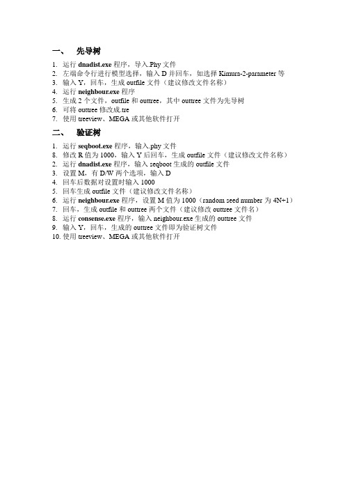
一、先导树
1.运行dnadist.exe程序,导入.Phy文件
2.左端命令行进行模型选择,输入D并回车,如选择Kimura-2-parameter等
3.输入Y,回车,生成outfile文件(建议修改文件名称)
4.运行neighbour.exe程序
5.生成2个文件,outfile和outtree,其中outtree文件为先导树
6.可将outtree修改成.tre
7.使用treeview、MEGA或其他软件打开
二、验证树
1.运行seqboot.exe程序,输入.phy文件
8.修改R值为1000,输入Y后回车,生成outfile文件(建议修改文件名称)
2.运行dnadist.exe程序,输入seqboot生成的outfile文件
3.设置M,有D/W两个选项,输入D
4.回车后数据对设置时输入1000
5.回车生成outfile文件(建议修改文件名称)
6.运行neighbour.exe程序,设置M值为1000(random seed number为4N+1)
7.回车,生成outfile和outtree两个文件(建议修改outtree文件名)
8.运行consense.exe程序,输入neighbour.exe生成的outtree文件
9.输入Y,回车,生成的outtree文件即为验证树文件
10.使用treeview、MEGA或其他软件打开。
基于虚拟仪器和小波降噪的植物电信号测量系统的设计

l tc inl ae f iulnt m n adw vlt e— o ig[ ] hns gi l rl c ai t n 2 1 ,( ) 9 9 e r a s a bsdo r a is u et n ae ni n J .C ieeA r ut a Mehnz i , 0 0 5 : 4~ 7 c il g vt r ed s c u ao
电波 口 。 早 先 的 研 究 集 中在 不 同 刺 激 条 件 下 所 产
生 的 电 信 号特 征 , 年 来 王 兰 州 等 通 过 对 微 弱 电信 近
号 的研 究 , 出 了 植 物 自身 的原 有 电 波 处 于 V级 提
・
屏蔽 网 :
・
量 级 j 。其 应 用研 究 主 要 是 环 境 变 化 与 信 号 特 征
了生长在营养袋中的健康橡胶苗 , 时域和频域两方 从 面对 信号进 行分 析 。
2 测 量 系统 的 设 计
2 1 总体 设计 .
通过引 导 电极 的植 物 电位 信号 , 过前 置放 大器 经 提高 增益倍 数 、 行工 频 陷波 和 lO z的低 通 滤 波等 进 OH 处理后 , 进入 数据采 集卡进 行模 数转 换 ; 过模 数 转换 经 后 的植 物 电位 信号 , 计算 机 的 Lb IW 环境 下进 行 在 aVE
实验 材料选 取 栽 培 的 、 树龄 为 3个 月 的大 戟 科 三
基 金 项 目: 南 省 自然科 学 基 金 项 目( 00 8 海 8 72 ) 陈 薇 , ,9 4年 生 , 女 18 陕西 宝 鸡 人 , 海南 大 学 机 电 工程 学 院硕 士 研 究生 ; 究 方 向 为 热带 农 业 生 产 过 程 中 的检 测 和 控 制 。 研
系统发育树构建教程(PHYLIP)

系统发育树构建教程(PHYLIP)PHYLIP网址:/phylip.html(一)序列的前期准备1.用ENTREZ或SRS搜索同源DNA/蛋白质序列(same sequence in different organisms) 2.用CLUSTALX进行多条序列比对,在output format option选定PHY格式,构建进化树需要这个phy文件。
Figure 4.1 用clustalx进行多条序列比对3.解压缩phylip-3.68.exe,得到三个文件夹,doc文件夹里是关于所有PHYLIP子程序的使用说明,exe文件夹里是直接可以使用的各个子程序,src文件夹里是所有程序的源文件。
4.打开exe文件夹,双击SEQBOOTt子程序(SEQBOOT是一个利用bootstrap方法产生伪样本的程序),输入刚刚生成的phy文件的路径,点击enter。
5.所有PHYLIP程序默认的输入文件名为infile, 输出文件名为outfile。
如果在exe文件夹里找不到默认的输入文件,会提示can’t find input file “infile”。
Figure 4.2 seqboot程序起始界面6.进入程序参数选择页面(Figure 4.3)。
第一列中的D、J、%、B、R、W、C、S等代表可选的参数。
想改变哪个参数,就键入此参数对应的字母,并点击回车键,对应参数将会发生改变。
当我们设置好所有参数后,(这里我们可以不做任何修改),键入Y,按回车。
此时程序询问“random numbe r seed? <must be odd>”,这是询问生成随机数的种子是多少,输入一个4N+1的数,点击回车程序开始运行,输出结果到文件outfile,保存在当前文件夹里。
.Figure 4.3 seqboot程序参数选择页面主要参数解释:D: 数据类型,有Molecular sequence、discrete morphology、restriction sites和gene frequencies4个选项。
基于小波消噪的植物电信号频谱特征分析

ZHANG a hu ,YU n me ,XIGa g MENG a l Xio i Ni g i n2 Xioi
,
( . aut o uo a o n fr ai nier g X ’nU i ri f ehoo , ia 10 8 hn ; 1 Fc l f t t na dI om t nE g e n , ia nv s y cnlg X ’n70 4 ,C ia y A m i n o n i e to T y 2 F cl f c ne X ’】 nvr t o eh o g , ia 10 4 C ia . aut o i c , ia y Se U i s y f cnl e i T o X ’ 705 , h ) y n n
研究 表 明植 物 内部存 在着 一种 涉及 电信 号及 其
信息 , 被接收细胞会 以特有的方式进行转换 , 进
而调 节植 物 的生理 变化 以适应 环 境的改 变 。该 方 面
转换的通讯途径 。环境刺激会使植物产生不同 的电位波动 。 推测 电位波动 的频率 、 4, 振幅 、 电信
号 的通讯
的研究有可能在植物生命科 学 中催生一 门新 的领
域— —植 物神 经生 物 学 。但 是 , 目前 只 知道 植 物
收稿 日期 : 0 10 -3 2 1 -60
基金项 目: 国家 自然科学基金资 助项 目(0709 ; 5977 )陕西省教育厅专项科研计划基金资助项 目(9K6 ) 0J67 。 作者简 介 : 张晓辉 (9 1)男 , 南郑 州人 , 18-, 河 博士生 , 研究 方 向为 大规模集 成 电路设 计及 相关信号 处理 。Em i x ou .a : ahi li . z@13cm h 6.o 。余宁梅 (93)女 , 苏南 京人 , 16一 , 江 教授 , 导 , 究方 向为 大规模 集成 电路设 计及相 关信 号处 博 研
LTE PHY
1.关于物理层的基础知识1.1物理层位于OSI参考模型的最底层,却是整个开放系统的基础。
物理层为设备之间的数据通信提供传输媒体及互连设备,为数据传输提供可靠的环境。
它直接面向实际承担数据传输的物理媒体(即通信通道),物理层的传输单位为比特(bit),即一个二进制位(―0‖或―1‖)。
实际的比特传输必须依赖于传输设备和物理媒体,但是,物理层不是指具体的物理设备,也不是指信号传输的物理媒体,而是指在物理媒体之上为上一层(数据链路层)提供一个传输原始比特流的物理连接。
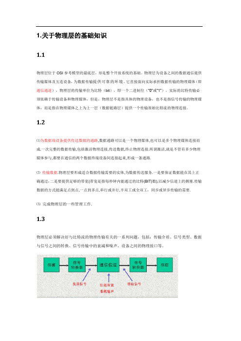
1.2⑴为数据端设备提供传送数据的通路,数据通路可以是一个物理媒体,也可以是多个物理媒体连接而成.一次完整的数据传输,包括激活物理连接,传送数据,终止物理连接.所谓激活,就是不管有多少物理媒体参与,都要在通信的两个数据终端设备间连接起来,形成一条通路.⑵传输数据.物理层要形成适合数据传输需要的实体,为数据传送服务.一是要保证数据能在其上正确通过,二是要提供足够的带宽(带宽是指每秒钟内能通过的比特(BIT)数),以减少信道上的拥塞.传输数据的方式能满足点到点,一点到多点,串行或并行,半双工或全双工,同步或异步传输的需要.⑶完成物理层的一些管理工作.1.3物理层必须解决好与比特流的物理传输有关的一系列问题,包括:传输介质、信号类型、数据与信号之间的转换、信号传输中的衰减和噪声、设备之间的物理接口等。
2.LTE PHY概述2.13GPP长期演进技术(LTE)是移动技术的一个重大进步。
LTE旨在满足运营商对高速数据和媒体传送以及高容量语音支持的需求,以帮助它们在下一个十年中赢得商机。
它包含高速数据、多媒本单播和多媒体广播业务。
LTE PHY是在增强型基站(eNodeB)和多动用户设备之间承载数据和控制信息的一种高效的手段。
LTE PHY采用了一些对移动应用来说非常先进的技术。
这些技术包括正交频分复用(OFDM)和多输入多输出(MIMO)数据传输。
LTEPUCCHDTX检测性能提升的新方法

无 线信道 多径 传输会 造
成频 率选 择性 衰落 终 端
,
UE
的移 动会 造 成 时 间选 择 性 衰
, ,
1 结束 图1
『
落 天 线 的不 同位置 会 造 成 空 间选 择 性 衰落 那 么
P UCCH
P U C C H 信 号处 理 示 意 图
, 、
性 能 的改善 必 须 要 充 分考虑 这 些 衰落 的 D T X 检 测 的 目的 是 为 了 防止
领 域 的投 人 从 而 推动 了
,
些 塑
LTE
…
的 不 断前 进
UCI
u a
引茎 兰 堡 燮 H !! 墨竺 H! H竺竺 L
— —
。
L T E P U CCH In fo r m
a
承载上 行控制信息
C QI ( C h a
n n e
( U p l in k Co n t r o l
a t io n
检 测 的 门限 可 以 更 好 地 抑 制 虚警
,
“
“
”
,
显 然提高了
“
UE
进行
DT X
判
“
” ,
降低 虚 警 概
因此 如何
,
决 所 需 要 的信 号 功 率 以 及 噪 声 功 率 进 而 得 到
所 需 的 信 噪 比 其 信 号功 率计算 式 如
,
DTx
判决
(1)
率 但 门 限越 高
, “ ”
u
,
a
n e w
m e
t ho
s
d is pr o po s e d in
u
丝琳基尔实验室开发的OpenThread 2.3.0.0 产品说明书
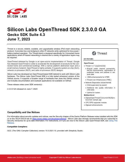
Silicon Labs OpenThread SDK 2.3.0.0 GA Gecko SDK Suite 4.3June 7, 2023Thread is a secure, reliable, scalable, and upgradeable wireless IPv6 mesh networking Array protocol. It provides low-cost bridging to other IP networks while optimized for low-power /battery-backed operation. The Thread stack is designed specifically for Connected Homeapplications where IP-based networking is desired and a variety of application layers maybe required.OpenThread released by Google is an open-source implementation of Thread. Googlehas released OpenThread in order to accelerate the development of products for the con-nected home and commercial buildings. With a narrow platform abstraction layer and asmall memory footprint, OpenThread is highly portable. It supports system-on-chip (SoC),network co-processor (NCP), and radio co-processor (RCP) designs.Silicon Labs has developed an OpenThread-based SDK tailored to work with Silicon Labshardware. The Silicon Labs OpenThread SDK is a fully tested enhanced version of theGitHub source. It supports a broader range of hardware than does the GitHub version,and includes documentation and example applications not available on GitHub.These release notes cover SDK version(s):2.3.0.0 GA released on June 7, 2023Compatibility and Use NoticesFor information about security updates and notices, see the Security chapter of the Gecko Platform Release notes installed with this SDK or on the TECH DOCS tab on https:///developers/thread . Silicon Labs also strongly recommends that you subscribe to Security Advisories for up-to-date information. For instructions, or if you are new to the Silicon Labs OpenThread SDK, see Using This Release.Compatible Compilers:GCC (The GNU Compiler Collection) version 10.3-2021.10, provided with Simplicity Studio.Contents1New Items (1)1.1New Components (1)1.2New Features (1)1.3New Radio Board Support (1)2Improvements (2)3Fixed Issues (3)4Known Issues in the Current Release (4)5Deprecated Items (5)6Removed Items (6)7Multiprotocol Gateway and RCP (7)7.1New Items (7)7.2Improvements (7)7.3Fixed Issues (7)7.4Known Issues in the Current Release (8)7.5Deprecated Items (8)7.6Removed Items (8)8Using This Release (9)8.1Installation and Use (9)8.2OpenThread GitHub Repository (9)8.3OpenThread Border Router GitHub Repository (9)8.4Using the Border Router (9)8.5NCP/RCP Support (10)8.6Security Information (10)8.7Support (11)New Items 1 New Items1.1 New ComponentsNone1.2 New FeaturesAdded in release 2.3.0.0•The versions of OpenThread and the OpenThread Border Router have been updated. See sections 8.2 and 8.3.•Thread 1.3.1 (experimental)o IPv4/v6 public internet connectivity: NAT64 improvements, optimization of published routes and prefixes in network data o DNS enhancements for OTBRo Thread over Infrastructure (TREL)•Network Diagnostics Improvements (experimental)o Child supervision by parento Additional link quality information in child tableo Uptime for routers•Support for the ot-cli sample application with CPC on Android Hosto The ot-cli sample application can now be used with CPC on an Android host. To build, download the Android NDK toolchain, define the environment variable "NDK" to point to the toolchain, and run the script/cmake-build-android script instead of script/cmake-build.1.3 New Radio Board SupportAdded in release 2.3.0.0Support has been added for the following radio boards:•BRD4196B - EFR32xG21B•BRD2704A - Sparkfun Thing Plus MGM240PImprovements 2 ImprovementsChanged in release 2.3.0.0•Support for “diag cw” and “diag stream”o diag cw start - Start transmitting continuous carrier waveo diag cw stop - Stop transmitting continuous carrier waveo diag stream start - Start transmitting a stream of characters.o diag stream stop - Stop transmitting a stream of characters.•Bootloader support for sample applicationso The bootloader_interface component has been added to the Thread sample apps. The component introduces support for bootloaders and also results in the creation of GBL files when building.•Reduction to code size of Certified OpenThread Librarieso The pre-built certification libraries no longer include JOINER functionality.Fixed Issues 3 Fixed IssuesFixed in release 2.3.0.01023725 Fixed an issue where detached MTDs on the Thread network hit an assert while re-attaching to the OTBR after the OTBR is rebooted.1079667 Fixed an issue where devices can no longer communicate after reporting transient out-of-buffers condition.1084368 Fixed failing HomeKit HCA test when using board 4186c and the DMP application.1095059 Added openthread 'diag stream' and 'diag cw' CLI commands. See Improvements section for additional details.1113046 Radio PAL now maintains max channel power table.1126570 Addressed a memory leak associated with PSA keys which occurs when otInstanceFinalise() is called without power cycling.1133240 Fixed a bug in setting link parameters in the meshcop forwarding layer.1139318 Request to Reduce Codesize of Certified OpenThread Library. See Improvements section for additional details. 1139449 Fixed an issue where devices stopped receiving during Tx storm.1142231 Radio SPINEL no longer asserts when no entries are available in source match table.Known Issues in the Current Release 4 Known Issues in the Current ReleaseIssues in bold were added since the previous release. If you have missed a release, recent release notes are available on https:///developers/thread in the Tech Docs tab.482915 495241 A known limitation with the UART driver can causecharacters to be lost on CLI input or output. This canhappen during particularly long critical sections thatmay disable interrupts, so it can be alleviated byrepeating the CLI or waiting long enough for statechanges.No known workaround754514 Double ping reply observed for OTBR ALOC address. No known workaround815275 Ability to modify the Radio CCA Modes at compile-time using a configuration option in Simplicity Studio is cur-rently not supported. Use the SL_OPENTHREAD_RADIO_CCA_MODE configuration option defined in openthread-core-efr32-config.h header file included with your project.1041112 OTBR / EFR32 RCP can miss forwarding packets froma CSL child if it configures an alternate channel for CSLcommunication.Due to this issue, OTBRs based on GSDK 4.2.0.0 arenot expected to pass Thread 1.2 certification unless thecustomer use cases demand a waiver to exclude alltests that require changing the primary channel. Avoid configuring alternate CSL channels until this issue is addressed.1094232 Intermittently, ot-ctl terminates after a factoryresetwhen using a CPCd connection.No known workaround1064242 OpenThread prefix commands sometimes fail to addprefix for OTBR over CPC.No known workaround1117447 Outgoing key index can be set to 0 under unknowncircumstances.No known workaround1132004 RCP can become unresponsive when receiving excessive beacon requests. This issue was seen with 3 devices sending beacons requests every 30 ms. Workaround is to reduce the number of beacon requesters and/or increase time between the requests.1143008 The OTBR can sometimes fail to transmit a CSL packet with the error "Handle transmit done failed:Abort". This could happen ifOPENTHREAD_CONFIG_MAC_CSL_REQUEST_AHEAD_US is set to low. SetOPENTHREAD_CONFIG_MAC_CSL_REQUEST_AHEAD_US to 5000.For the OTBR, you can either:1. Modify the value ofOPENTHREAD_CONFIG_MAC_CSL_REQUEST_AHEAD_US in ot-br-posix/third_party/openthread/repo/src/core/config/mac.hor2. Pass the value during setup as follows:sudo OTBR_OPTIONS="-DCMAKE_CXX_FLAGS='-DOPENTHREAD_CONFIG_MAC_CSL_REQUEST_AHEAD_ US=5000'" ./script/setup1148720 Intermittently, SED current draw is too high. No known workaroundDeprecated Items 5 Deprecated ItemsNone.Removed Items 6 Removed ItemsRemoved in release 2.3.0.0•The ot-remote-cli component has been removed. There is no replacement for this component because the functionality provided by the component is no longer required.•The Silicon Labs HomeKit extension is no longer included with this release.7 Multiprotocol Gateway and RCP7.1 New ItemsAdded in release 2.3.0.0Added a new application z3-light_ot-ftd_soc that demonstrates Zigbee and OpenThread Concurrent Multiprotocol functionality. It features a router on the Zigbee side and a Full Thread Device (FTD) on the OpenThread side. See the project description or app/framework/sce-narios/z3/z3-light_ot-ftd_soc/readme.html for details.First GA-quality release of CPC GPIO Expander module. The Co-Processor Communication (CPC) General Purpose Input/Output (GPIO) Expander is a software component designed to enable a Host device to utilize a Secondary device's GPIOs as if they were its own. With the CPC GPIO Expander, the Host device can seamlessly integrate with the Secondary device and make use of its GPIO capabilities. See https:///SiliconLabs/cpc-gpio-expander/README.md for documentation.Added antenna diversity and coex EZSP command support to Zigbeed.Added better assert reporting to Zigbeed.Added bt_host_empty application (option: -B for the run.sh script) to the multiprotocol docker container.Zigbeed now includes an implementation of emberGetRestoredEui64() which loads the CREATOR_STACK_RESTORED_EUI64 token from the host_token.nvm file.The multiprotocol container now sets the size of syslog to 100 MB by default. Users are able to change the size by modifying the "/etc/logrotate.d/rsyslog" and "/etc/rsyslog.d/50-default.conf" files and restarting the rsyslog service inside the container.7.2 ImprovementsChanged in release 2.3.0.0Reduced CPC Tx and Rx queue sizes to fit the DMP NCP on the MG13 family.Configured options on the multiprotocol RCP projects to provide ~3.3k in RAM savings, particularly for the MG1 part. This was accom-plished by•Reducing•The number of user CPC endpoints to 0•Tx CPC queue size to 15 from 20•Rx buffer count to 15•Disabling OpenThread RTT logsFor further savings, customers can look into reducing the Tx and Rx queue sizes further. Note that the downside to this change would be a reduction in message throughput due to added retries. Also, customers can look into reducing the NVM cache size based on need. As a last resort, customers may also choose to disable CPC security on both the RCP and the host. We do not recommend the last option.Changed zigbee_ble_event_handler to print scan responses from legacy advertisements in the DMPLight(Sed) app.The rcp-xxx-802154 apps now by default support 192 µsec turnaround time for non-enhanced acks while still using 256 µsec turnaround time for enhanced acks required by CSL.7.3 Fixed IssuesFixed in release 2.3.0.01078323 Resolved issue where Z3GatewayCPC asserts when there is a communication failure with the NCP during address table initialization. We will now try to reconnect to the NCP upon failure.1080517 Z3GatewayCPC now automatically handles a reset of the NCP (CPC secondary).1117789 Fixed an issue where modifying OPENTHREAD_CONFIG_PLATFORM_RADIO_SPINEL_RX_FRAME_BUFFER_SIZE caused a linker error when building Zigbeed.1118077 In the CMP RCP, Spinel messages were being dropped under heavy traffic load due to CPC not keeping up with the incoming packets. Fixed this by bundling all Spinel messages ready to be sent over CPC into one payload on the RCP and unbundling them on the host. This dramatically improves the efficiency of CPC so that it can keep up with the incoming radio traffic.1129821 Fixed null pointer dereference in Zigbeed in an out-of-buffer scenario while receiving packets.1139990 Fixed an assert in the OpenThread Spinel code that could be triggered when joining many Zigbee devices simultaneously.1144268 Fixed an issue where excessive radio traffic can cause the Zigbee-BLE NCP to get into a state where it continually executes the NCP and CPC initialization.1147517 Fixed an issue with Z3GatewayCPC on startup that could cause the reset handling of the secondary to not work correctly.7.4 Known Issues in the Current ReleaseIssues in bold were added since the previous release. If you have missed a release, recent release notes are available on https:///developers/gecko-software-development-kit.811732 Custom token support is not available when using Zigbeed. Support is planned in a future release.937562 Bluetoothctl ‘advertise on’ command fails with rcp-uart-802154-blehci app on Raspberry Pi OS 11.Use btmgmt app instead of bluetoothctl.1074205 The CMP RCP does not support two networks on the same PAN id. Use different PAN ids for each network. Support is planned in a future release.1122723 In a busy environment the CLI can become unresponsive in the z3-light_ot-ftd_soc app. This app is released as experimental quality and the issue will be fixed in a future release.1124140 z3-light_ot-ftd_soc sample app is not able to form theZigbee network if the OT network is up already.Start the Zigbee network first and the OT network after.1129032 Experimental concurrent listening feature on xG24 de-vices is disabled in this release.Support is planned in a future release.1143857 Antenna Diversity is not available on the CMP RCP forxG21 and xG24 parts, since the antenna diversityhardware is used for concurrent listening.Intended behavior.7.5 Deprecated Items None7.6 Removed Items None8 Using This ReleaseThis release contains the following•Silicon Labs OpenThread stack•Silicon Labs OpenThread sample applications•Silicon Labs OpenThread border routerFor more information about the OpenThread SDK see QSG170: Silicon Labs OpenThread QuickStart Guide. If you are new to Thread see UG103.11: Thread Fundamentals.8.1 Installation and UseThe OpenThread SDK is part of the Gecko SDK (GSDK), the suite of Silicon Labs SDKs. To quickly get started with OpenThread and the GSDK, start by installing Simplicity Studio 5, which will set up your development environment and walk you through GSDK installation. Simplicity Studio 5 includes everything needed for IoT product development with Silicon Labs devices, including a resource and project launcher, software configuration tools, full IDE with GNU toolchain, and analysis tools. Installation instructions are provided in the online Simplicity Studio 5 User’s Guide.Alternatively, Gecko SDK may be installed manually by downloading or cloning the latest from GitHub. See https:///Sili-conLabs/gecko_sdk for more information.The GSDK default installation location has changed beginning with Simplicity Studio 5.3.•Windows: C:\Users\<NAME>\SimplicityStudio\SDKs\gecko_sdk•MacOS: /Users/<NAME>/SimplicityStudio/SDKs/gecko_sdkDocumentation specific to the SDK version is installed with the SDK. API references and other information about this release are available on https:///openthread/2.1/.8.2 OpenThread GitHub RepositoryThe Silicon Labs OpenThread SDK includes all changes from the OpenThread GitHub repo (https:///openthread/openthread) up to and including commit dae3ff2c5. An enhanced version of the OpenThread repo can be found in the following Simplicity Studio 5 GSDK location:<GSDK Installation Location>\util\third_party\openthread8.3 OpenThread Border Router GitHub RepositoryThe Silicon Labs OpenThread SDK includes all changes from the OpenThread border router GitHub repo (https:///openthread/ot-br-posix) up to and including commit de7cd7b20. An enhanced version of the OpenThread border router repo can be found in the following Simplicity Studio 5 GSDK location:<GSDK Installation Location>\util\third_party\ot-br-posix8.4 Using the Border RouterFor ease of use, Silicon Labs recommends the use of a Docker container for your OpenThread border router. Refer to AN1256: Using the Silicon Labs RCP with the OpenThread Border Router for details on how to set up the correct version of OpenThread border router Docker container. It is available at https:///r/siliconlabsinc/openthread-border-router.If you are manually installing a border router, using the copies provided with the Silicon Labs OpenThread SDK, refer to AN1256: Using the Silicon Labs RCP with the OpenThread Border Router for more details.Although updating the border router environment to a later GitHub version is supported on the OpenThread website, it may make the border router incompatible with the OpenThread RCP stack in the SDK.8.5 NCP/RCP SupportThe OpenThread NCP support is included with OpenThread SDK but any use of this support should be considered experimental. The OpenThread RCP is fully implemented and supported.8.6 Security InformationSecure Vault IntegrationWhen deployed to Secure Vault High devices, sensitive keys are protected using the Secure Vault Key Management functionality. The following table shows the protected keys and their storage protection characteristics.Thread Master Key Exportable Must be exportable to form the TLVsPSKc Exportable Must be exportable to form the TLVsKey Encryption Key Exportable Must be exportable to form the TLVsMLE Key Non-ExportableTemporary MLE Key Non-ExportableMAC Previous Key Non-ExportableMAC Current Key Non-ExportableMAC Next Key Non-ExportableWrapped keys that are marked as “Non-Exportable” can be used but cannot be viewed or shared at runtime.Wrapped keys that are marked as “Exportable” can be used or shared at runtime but remain encrypted while stored in flash.For more information on Secure Vault Key Management functionality, see AN1271: Secure Key Storage.Security AdvisoriesTo subscribe to Security Advisories, log in to the Silicon Labs customer portal, then select Account Home. Click HOME to go to the portal home page and then click the Manage Notifications tile. Make sure that ‘Software/Security Advisory Notices & Product Change Notices (PCNs)’ is checked, and that you are subscribed at minimum for your platform and protocol. Click Save to save any changes.8.7 SupportDevelopment Kit customers are eligible for training and technical support. Use the Silicon Laboratories Thread web page to obtain infor-mation about all Silicon Labs OpenThread products and services, and to sign up for product support.You can contact Silicon Laboratories support at /support.Silicon Laboratories Inc.400 West Cesar Chavez Austin, TX 78701USA IoT Portfolio /IoT SW/HW /simplicity Quality /quality Support & Community /communityDisclaimerSilicon Labs intends to provide customers with the latest, accurate, and in-depth documentation of all peripherals and modules available for system and software imple-menters using or intending to use the Silicon Labs products. Characterization data, available modules and peripherals, memory sizes and memory addresses refer to each specific device, and “Typical” parameters provided can and do vary in different applications. Application examples described herein are for illustrative purposes only. Silicon Labs reserves the right to make changes without further notice to the product information, specifications, and descriptions herein, and does not give warranties as to the accuracy or completeness of the included information. Without prior notification, Silicon Labs may update product firmware during the manufacturing process for security or reliability reasons. Such changes will not alter the specifications or the performance of the product. Silicon Labs shall have no liability for the consequences of use of the infor -mation supplied in this document. This document does not imply or expressly grant any license to design or fabricate any integrated circuits. The products are not designed or authorized to be used within any FDA Class III devices, applications for which FDA premarket approval is required or Life Support Systems without the specific written consent of Silicon Labs. A “Life Support System” is any product or system intended to support or sustain life and/or health, which, if it fails, can be reasonably expected to result in significant personal injury or death. Silicon Labs products are not designed or authorized for military applications. Silicon Labs products shall under no circumstances be used in weapons of mass destruction including (but not limited to) nuclear, biological or chemical weapons, or missiles capable of delivering such weapons. Silicon Labs disclaims all express and implied warranties and shall not be responsible or liable for any injuries or damages related to use of a Silicon Labs product in such unauthorized applications. Note: This content may contain offensive terminology that is now obsolete. Silicon Labs is replacing these terms with inclusive language wherever possible. For more information, visit /about-us/inclusive-lexicon-projectTrademark InformationSilicon Laboratories Inc.®, Silicon Laboratories ®, Silicon Labs ®, SiLabs ® and the Silicon Labs logo ®, Bluegiga ®, Bluegiga Logo ®, EFM ®, EFM32®, EFR, Ember ®, Energy Micro, Energy Micro logo and combinations thereof, “the world’s most energy friendly microcontrollers”, Redpine Signals ®, WiSeConnect , n-Link, ThreadArch ®, EZLink ®, EZRadio ®, EZRadioPRO ®, Gecko ®, Gecko OS, Gecko OS Studio, Precision32®, Simplicity Studio ®, Telegesis, the Telegesis Logo ®, USBXpress ® , Zentri, the Zentri logo and Zentri DMS, Z-Wave ®, and others are trademarks or registered trademarks of Silicon Labs. ARM, CORTEX, Cortex-M3 and THUMB are trademarks or registered trademarks of ARM Holdings. Keil is a registered trademark of ARM Limited. Wi-Fi is a registered trademark of the Wi-Fi Alliance. All other products or brand names mentioned herein are trademarks of their respective holders.。
- 1、下载文档前请自行甄别文档内容的完整性,平台不提供额外的编辑、内容补充、找答案等附加服务。
- 2、"仅部分预览"的文档,不可在线预览部分如存在完整性等问题,可反馈申请退款(可完整预览的文档不适用该条件!)。
- 3、如文档侵犯您的权益,请联系客服反馈,我们会尽快为您处理(人工客服工作时间:9:00-18:30)。
LTE PHY FundamentalsRoger Piqueras JoverDL Physical Channels-DL-SCH: The DownLink Shared CHannel is a channel used to transport down-link user data or Radio Resource Control (RRC) messages, as well as system information which are nottransported via the Broadcast CHannel (BCH).-PBCH: The Physical Broadcast CHannel carries the Master Information Block (MIB). It consists ofa limited number of the most frequently transmitted parameters essential for initial access tothe cell. The PBCH is designed for early detection by the UE, and cell-wide coverage.-PDSCH: The Physical Downlink Shared CHannel is the main downlink data-bearing channel in LTE, used for all user data, as well as for broadcast system information which is not carried onthe Physical Broadcast CHannel (PBCH). It is also used for paging messages.-PDCCH: The Physical Downlink Control CHannel is a downlink control channel used to support efficient data transmission in LTE. A PDCCH carries a message known as Downlink ControlInformation (DCI), which includes transmission resource assignments and other controlinformation for a UE or group of UEs. Many PDCCHs can be transmitted in a subframe.-PCFICH: The Physical Control Format Indicator CHannel is a downlink physical channel that carries a Control Format Indicator (CFI) which indicates the number of OFDM symbols (i.e.normally 1, 2 or 3) used for transmission of downlink control channel information in eachsubframe.-PHICH: The Physical Hybrid ARQ Indicator CHannel is a downlink physical channel that carries the Hybrid ARQ (HARQ) ACK/NACK information indicating whether the eNodeB has correctlyreceived a transmission on the Physical Uplink Shared CHannel (PUSCH). Multiple PHICHs (fordifferent UEs) are mapped to the same set of downlink resource elements. These constitute aPHICH group, where different PHICHs within the same PHICH group are separated throughdifferent complex orthogonal Walsh sequences.Design constraintsThe two basic principal physical parameters are the cyclic prefix length (Tg) and the sub-carrier spacing (Δf). There are several design constraints to select these two parameters, and the standard tries to find a trade-off with the optimal values holding the constraints.First of all, Tu should be as larger than Tg as possible so the system has low overhead (Tu >> Tg). It is important to keep in mind that Tu has to be sufficiently small to ensure that the channel does not vary within one OFDM symbol.Tg has to be large enough to avoid Inter Symbol Interference (ISI). This is, Tg should be larger than the delay spread (Td) of the channel. LTE has different configurations depending on the type of channel through which the system is transmitting (Tg > Td).Finally, considering a mobile UE, there is going to be a deviation in frequency from the expected carrier frequency. This is due to the Doppler Effect. This deviation in frequency will have a maximum value off dmax=v/λ0, being λ0 the wavelength associated to the systems carrier frequency. Note that the Doppler Effect will be more noticeable at the further subcarriers from the DC component of the OFDM base-band system.In order to attenuate the effects of Inter Carrier Interference (ICI), it is required that f dmax/Δf << 1. This implies that Δf has to be large enough to overcome ICI (Δf >> f dmax).Recall that Tu=1/Δf, so one has to find a trade-off between Tu/Tg and Δf.Delay spread-Urban environment (maximum delay spread of 15μs): Among the 3 possible configurations listed in the LTE standard, in this kind of environment the chosen parameters would be Δf=15KHz and CP=17μs (Extended CP mode). This value of Δf is the most common one and is determined inorder to be able to serve users moving at a velocity of up to 500km/h. The chosen length of the cyclic prefix is enough to avoid ISI.-Indoor environment (maximum delay spread of 1μs): In this case, the chosen parameters would be Δf=15KHz and CP=5μs(Normal parametrization). Again, the chosen value of Δf would beenough to cover speeds of up to 500km/h and a shorter CP s enough to avoid ISI with a delayspread of 1μs.Mapping of reference signalsThe cell-specific reference signals are pilot signals inserted into the downlink signal that are used by the UE to perform downlink channel estimation in order to perform coherent demodulation of the information-bearing parts of the downlink signal. These signals are modulated using QPSK to make them resilient to noise and errors and they carry one of the 504 different cell identities. They are also transmitted in a power boosted way (6dB more than surrounding data symbols) so they are easily detected, received and demodulated.It can be shown that in an OFDM-based system an equidistant arrangement of reference symbols in the lattice structure achieves the minimum mean squared error estimate of the channel. Moreover, in the case of a uniform reference symbol grid, a ‘diamond shape’ in the time-frequency plane can be shown to be optimal.The placing of these reference signals in the time-frequency lattice is constrained both in time and frequency.Time domain requirements:The required spacing in the time domain between reference signals is forced by the Doppler Effect. The maximum Doppler frequency determines how fast the channel changes in time (coherence timeτc~1/f dmax). The LTE standard considers speeds of up to 500km/h. At a carrier frequency of 2GHz, this speed represents a maximum Doppler shift of f dmax~ 950Hz. Given Nyquist’s sampling theorem, the minimum sampling period required to reconstruct a channel with a Doppler shift of 950Hz isT min=1/(2f dmax)≈0.5ms under the above assumptions. This implies that two reference symbols per slot are needed in the time domain in order to estimate the channel correctly.Frequency domain requirementsThe required spacing in the frequency domain between reference signals s forced by the Coherence Bandwidth of the channel. This bandwidth can be defined in different ways depending on the degree of decorrelation in percentage. For example, a 50% coherence bandwidth is defined as the separation in frequency such that the cross correlation between two frequency samples of the channel is 0.5.The coherence bandwidth of the wireless channel si directly related to the Delay Spread (δτ) of the channel. The coherence bandwith (50% and 90%) can be approximated as B c,90%=1/(50 δτ) andB c,50%=1/(5δτ). The maximum r.m.s channel delay spread considered in the standard is 991 ns, corresponding to B c,90%≈20KHz and B c,50%≈200KHz.In LTE the spacing between two reference symbols in frequency, in one RB, is 45 kHz, thus allowing the expected frequency domain variations of the channel to be resolved. Therefore, in the frequency direction there is one reference symbol every six subcarriers on each OFDM symbols which includesreference symbol, but these are staggered so that within each Resource Block (RB) there is one reference symbol every 3 subcarriers.LTE FDD DL radio framea)Radio frame structure (1.4MHz BW, 1 antenna port, CFI=2)b)Overhead and peak rate throughput (64-QAM, 5.5547 bits per symbol)CFI=2Given the BW of 1.4MHz, there are only 6 RBs available. For CFI=2 the structure of the frame is the same as the one depicted in section (6.a). As can be seen above, there are 6x10=60 blocks of (1RB x 1 subframe), organized in 10 columns with 6 RB each one.8 of the columns will be of the type a (shown above), 1 column of type a and 1 column of type c. Let’s compute the number of resource elements used for data and the ones used for control information per each time of column:-Column (a):CFI + PBCH + reference + PSS/SSS= 2x12+6x12+4=100 control resource elements 12x14-100= 68 data resource elements-Column (b):CFI + reference + PSS/SSS= 2x12+2x12+6= 54 control resource elements12x14-54= 114 data resource elements-Column (c):CFI + reference= 2x12+6=30 control resource elements12x14-30= 138 data resource elementsThe overhead can be calculated as:Total control=(1 column a)x(6x100)+(1 column b)x(6x54)+(8 columns c)x(6x30)=2364 resource elements Total resource elements=(6x12)x(10x14)=10080Overhead (CFI=2)= 100 x (2364/10080)=23.45%One information symbol can be allocated in each data resource element. The transmission is done by means of 64-QAM with an average of 5.5547 bits per symbol. The peak rate thorughput is:Total data=(1 column a)x(6x68)+(1 column b)x(6x114)+(8 columns c)x(6x138)=7716 resource elements Peak rate= (7716 symbols x 5.5547 bits/symbol)/10ms= 4.28MbpsCFI=3With CFI=3, the number of data and control resource elements in each column changes as follows: -Column (a):CFI + PBCH + reference + PSS/SSS= 3x12+6x12+4=112 control resource elements 12x14-112= 56 data resource elements-Column (b):CFI + reference + PSS/SSS= 3x12+2x12+6= 66 control resource elements12x14-66= 102 data resource elements-Column (c):CFI + reference= 3x12+6=42 control resource elements12x14-42= 126 data resource elementsTotal control=1x(6x112)+1x(6x66)+8x(6x42)=3084 resource elementsTotal resource elements=(6x12)x(10x14)=10080Overhead (CFI=2)= 100 x (3084/10080)=30.59%Total data=(1 column a)x(6x56)+(1 column b)x(6x10²)+(8 columns c)x(6x126)=6996 resource elements Peak rate= (6996 symbols x 5.5547 bits/symbol)/10ms= 3.89 MbpsCFI=4With CFI=4, the number of data and control resource elements in each column changes as follows: -Column (a):CFI + PBCH + reference + PSS/SSS= 4x12+6x12+4=124 control resource elements 12x14-124= 44 data resource elements-Column (b):CFI + reference + PSS/SSS= 4x12+2x12+6= 78 control resource elements12x14-78= 90 data resource elements-Column (c):CFI + reference= 4x12+6=54 control resource elements12x14-54= 114 data resource elementsTotal control=1x(6x124)+1x(6x78)+8x(6x54)=3804 resource elementsTotal resource elements=(6x12)x(10x14)=10080Overhead (CFI=2)= 100 x (3804/10080)=37.74%Total data=(1 column a)x(6x44)+(1 column b)x(6x90)+(8 columns c)x(6x114)=6276 resource elements Peak rate= (6276 symbols x 5.5547 bits/symbol)/10ms= 3.48 MbpsSo, the final results are as shown in the table:Scenario CFI Overhead [%] Peak rate [Mbps]1 2 23.45 4.282 3 30.59 3.893 4 37.74 3.48LTE FDD DL radio frame (BW=20MHz)a)Radio frame structure (20MHz BW, 4 antenna ports, CFI=2)b)Overhead and peak rate throughput (64-QAM, 5.5547 bits per symbol)Given 20MHz of available spectrum, there are 100 Resource Blocks available. Note that the 6 central ones contain PBCH, PSS/SSS, CFI and the reference signals (for a 4 antenna port configuration) while The remaining 94 RBs contain only CFI and the reference signals.CFI=1Let’s recalculate the amount of data and control block per each kind of subframe:-Column (a):CFI + PBCH + reference + PSS/SSS= 1x12+6x12+12=96 control resource elements 12x14-96= 72 data resource elements-Column (b):CFI + reference + PSS/SSS= 1x12+2x12+20= 56 control resource elements12x14-64= 112 data resource elements-Column (c):CFI + reference= 1x12+20=32 control resource elements12x14-40= 136 data resource elementsThe overhead can be calculated as:Total control=(1 column a)x(6x96)+(1 column b)x(6x56)+(8 columns c)x(6x32) ++ (94x10 columns c)x32=32528 resource elementsTotal resource elements=(100x12)x(10x14)=168000Overhead (CFI=2)= 100 x (32528/168000)=19.36%One information symbol can be allocated in each data resource element. The transmission is done by means of 64-QAM with an average of 5.5547 bits per symbol. The peak rate thorughput is:Total data=(1 column a)x(6x72)+(1 column b)x(6x112)+(8 columns c)x(6x136) ++ (94x10 columns c)x136=135472 resource elementsPeak rate= 4 x (135472 symbols x 5.5547 bits/symbol)/10ms= 301 MbpsCFI=2Let’s recalculate the amount of data and control block per each kind of subframe:-Column (a):CFI + PBCH + reference + PSS/SSS= 2x12+6x12+8=104 control resource elements 12x14-104= 64 data resource elements-Column (b):CFI + reference + PSS/SSS= 2x12+2x12+16= 64 control resource elements12x14-64= 104 data resource elements-Column (c):CFI + reference= 2x12+16=40 control resource elements12x14-40= 128 data resource elementsThe overhead can be calculated as:Total control=(1 column a)x(6x10⁴)+(1 column b)x(6x64)+(8 columns c)x(6x40) ++ (94x10 columns c)x40=40528 resource elementsTotal resource elements=(100x12)x(10x14)=168000Overhead (CFI=2)= 100 x (40528/168000)=24.12%One information symbol can be allocated in each data resource element. The transmission is done by means of 64-QAM with an average of 5.5547 bits per symbol. The peak rate thorughput is:Total data=(1 column a)x(6x64)+(1 column b)x(6x10⁴)+(8 columns c)x(6x128) ++ (94x10 columns c)x128=127472 resource elementsPeak rate= 4 x (127472 symbols x 5.5547 bits/symbol)/10ms= 283.23 MbpsCFI=3Let’s recalculate the amount of data and control block per each kind of subframe:-Column (a):CFI + PBCH + reference + PSS/SSS= 3x12+6x12+8=116 control resource elements 12x14-116= 52 data resource elements-Column (b):CFI + reference + PSS/SSS= 3x12+2x12+16= 76 control resource elements12x14-76= 92 data resource elements-Column (c):CFI + reference= 3x12+16=52 control resource elements12x14-52= 116 data resource elementsThe overhead can be calculated as:Total control=(1 column a)x(6x116)+(1 column b)x(6x76)+(8 columns c)x(6x52) ++ (94x10 columns c)x52=52528 resource elementsTotal resource elements=(100x12)x(10x14)=168000Overhead (CFI=2)= 100 x (52528/168000)=31.27%One information symbol can be allocated in each data resource element. The transmission is done by means of 64-QAM with an average of 5.5547 bits per symbol. The peak rate thorughput is:Total data=(1 column a)x(6x52)+(1 column b)x(6x92)+(8 columns c)x(6x116) ++ (94x10 columns c)x116=115472 resource elementsPeak rate= 4 x (115472 symbols x 5.5547 bits/symbol)/10ms= 256.56 MbpsSo, the final results are as shown in the table:Scenario CFI Overhead [%] Peak rate [Mbps]1 1 19.36 3012 2 24.12 283.233 3 31.27 256.56We observe that, as stated in the standard, the peak bit-rate of LTE is about 300 Mbps.。