Magic RP 指南
Magics RP 指南

Magics RP 教程该教程介绍了一些Magics RP 的工具。
使用该教程将使用户更快的了解和使用本软件。
一、视图和测量visualization and measuring目测教程所使用的文件是在目录../Magics RP .../demo_files 下的文件“Good.stl”。
打开文件可以用快捷键‘Ctrl + L’或按按钮。
这时也可以到网上浏览,查找STL格式的文件。
图1-1一个文件可以有不同的显示方式(在View 工具栏里)。
图1-2试用这些模式。
用'F4'键或图标可以控制视角。
在零件上托动鼠标可以看到零件是如何旋转的。
当指针接近窗口中心时,指针将会变成四角箭头形状,指针的移动将转变为零件绕屏幕的轴转动。
当指针靠近窗口边界时,指针将变成圆弧箭头形状,零件就可以绕垂直于屏幕的轴转动。
用户同样可以按住鼠标右键来旋转零件。
要快速定位可以用默认的视图。
该图标可以在view 工具栏中的Rotate标签下找到。
本软件预设了七种默认视图:主视、后视、左视、右视、俯视、仰视和ISO视图。
这些视图可通过点击某一个箭头来切换(当指针移过箭头时箭头会高亮显示)。
当立方体的所有边界都高亮显示时就选中了ISO视图(在紫色区域内点击,或在边界上点击)。
使用图标,用户可以在窗口平面内托动零件移动(按住鼠标左键不放)。
该功能也可以通过以下方法实现:菜单Main Menu/View/Pan 或用快捷键'Alt + M'。
或同时按着鼠标右键+SHIFT。
可以用SECTIONS 指令来检查零件内部。
Sections 指令在view工具栏下的Sections标签内。
图1-3用户可以在垂直于X、Y和Z轴方向上取得截面。
用户可以隐藏前面部分并让零件挖空显示。
二、修改STL文件的“远程控制”Fixing STL Files "remote control"修改远程控制本教程主要介绍一些STL修改工具。
Magic RP 指南

Magics RP 教程该教程介绍了一些Magics RP 的工具。
使用该教程将使用户更快的了解和使用本软件。
一、视图和测量visualization and measuring目测教程所使用的文件是在目录../Magics RP .../demo_files 下的文件“Good.stl”。
打开文件可以用快捷键‘Ctrl + L’或按按钮。
这时也可以到网上浏览,查找STL格式的文件。
图1-1一个文件可以有不同的显示方式(在View 工具栏里)。
图1-2试用这些模式。
用'F4'键或图标可以控制视角。
在零件上托动鼠标可以看到零件是如何旋转的。
当指针接近窗口中心时,指针将会变成四角箭头形状,指针的移动将转变为零件绕屏幕的轴转动。
当指针靠近窗口边界时,指针将变成圆弧箭头形状,零件就可以绕垂直于屏幕的轴转动。
用户同样可以按住鼠标右键来旋转零件。
要快速定位可以用默认的视图。
该图标可以在view 工具栏中的Rotate标签下找到。
本软件预设了七种默认视图:主视、后视、左视、右视、俯视、仰视和ISO视图。
这些视图可通过点击某一个箭头来切换(当指针移过箭头时箭头会高亮显示)。
当立方体的所有边界都高亮显示时就选中了ISO视图(在紫色区域内点击,或在边界上点击)。
使用图标,用户可以在窗口平面内托动零件移动(按住鼠标左键不放)。
该功能也可以通过以下方法实现:菜单Main Menu/View/Pan 或用快捷键'Alt + M'。
或同时按着鼠标右键+SHIFT。
可以用SECTIONS 指令来检查零件内部。
Sections 指令在view工具栏下的Sections标签内。
图1-3用户可以在垂直于X、Y和Z轴方向上取得截面。
用户可以隐藏前面部分并让零件挖空显示。
二、修改STL文件的“远程控制”Fixing STL Files "remote control"修改远程控制本教程主要介绍一些STL修改工具。
MagicLantern使用说明用户指南翻译
MagicLantern使用说明用户指南翻译破解程序所带的用户指南pdf文件为蓝本翻译,可能与其它版本有些差异。
特点* 音频:可禁用AGC和数字滤波器,音频电平显示,手动音频控制,选择使用输入源(内部+外部,内部,外部立体声,平衡),通过USB端口监控音频。
* 曝光助手:斑马,伪色,直方图,波形,中心点测光。
* 对焦工具:焦点峰值,录像时画面焦点放大,陷阱对焦,变焦,跟焦,焦点叠加合成,焦点图,面部优先检测模式下画面放大。
* 短片助手:比特率控制(QScale或CBR),短片日志记录(EXIF元数据),缓冲区溢出或4GB限制后自动重新启动,剩余时间显示,LiveView显示时隐去所有覆盖,改变模式拨盘上的短片模式键的位置。
* 幅面裁切标记:用户可自编辑幅面裁切标记图像,以协助取景和构图。
* 精细控制ISO,快门,K级白平衡和其他图像设置。
* 用LCD面部感应器和音频触发器遥控触发,无需额外的硬件。
* 包围:包围曝光,焦点叠加合成。
* Timelapse:间隔时间拍摄(照片和短片),无需快门驱动的无声照片; 包围曝光及合成。
* 天文夜间摄影:很长时间(高达8H)的B门曝光。
* 信息显示:焦点和DOF信息,CMOS温度,快门计数器和时钟。
* 对于闪客:从-10到+3 EV的闪光曝光补偿。
* 电源管理:LiveView 模式下的关闭显示,快速调整LCD背光级别。
* 有趣的东西:无声扫描照片。
重要注意事项:* 如果你有一个可引导的SD卡,并有DISKBOOT文件在相机里(安装程序的那个),而卡上没有AUTOEXEC.BIN文件,相机将无法启动!这时先取出电池,然后做其它。
* 如果你遇到相机“锁定”,请迅速取出电池。
否则ARM可能进入一个循环,更热,更迅速...... 你的电池会很快没电,您的液晶显示器可能会变色。
* 当有疑问时,请取出电池,然后重新启动。
* 请记住,这个软件可以搞坏你的相机。
常见问题一1、我如何清除所有的图像,而不删除的ML?佳能相机菜单(回放)--删除图像--卡上的所有图像。
MagicPak 壁套套件安装说明说明书

506390-01Manufactured ByAllied Air Enterprises LLCA Lennox International, Inc. Company215 Metropolitan Drive West Columbia, SC 29170This manual must be left with the homeowner for future reference.(P) 506390-01*P506390-01*WARNINGWARNINGWARNINGThe wall sleeve is designed to facilitate the installation of MagicPak ® units by providing an accurate opening during building construction. The use of a wall sleeve allows units to remain off-site until building construction approaches completion.A louver kit must be used along with the wall sleeve kit in all MagicPak ® installations. Louver kits are not included with the wall sleeve kits.Inspection of ShipmentIf any damage to the contents of this kit is found at the time of delivery, proper notification should be made on the carrier’s freight bill. Damage claims should be filed with the carrier at once. Claims of shortage should be filed with the manufacturer within 5 days.To assemble and install the wall sleeve, refer to the following instructions. Everything needed to assemble and install the wall sleeve is included in the kit except deck screws, caulk, and flashing.Installation Preparation1. Inspect the wall opening. Make sure that it is theproper size (see the Required Wall Opening drawing on Page 9).2. Before the wall sleeve can be installed, a platform mustbe built to support the MagicPak® unit. The platform may be constructed of plywood and 2 x 4’s. Recommended Height of Platform: The platform must be made level to the sill plate of the wall opening (Figure 1). Minimum height of platform is 4”.Figure 1. Platform AssemblyRecommended Width: 30”Recommended Depth: The platform depth must support the entire depth of unit. Unit depth plus the distance the unit is mounted away from the wall is recommended platform depth (Figure 1). Inside flange of top panel may not fit flush to inside wall. If it does not, the distance between the wall and the top panel flange must be added to the unit depth measurement to determine the recommended platform depth. Example: Wall sleeve kit ASLEEVE8-1 is 8” deep. If that wall sleeve is installed on a wall that is 6” thick, there would be a 2” difference. That 2” must be added to the unit depth (either 21-1/2” or 24-1/2” depending on the unit) to determine the recommended platform depth for that installation.Wall Sleeve Assembly1. Place plastic base of wall sleeve on flat surface asshown in Figure 2.2. Caulk each side of base panel as shown.3. Install both right and left side panel assemblies onbase panel using sheet metal screws (provided). Use three screws (numbered 1, 2, and 3 in Figure 2) perside as shown in Figure 2.Figure 2. Attaching Side Panels to Base4. Install top panel assembly onto side panels as shownin Figure 3.NOTE: Top panel fits on outside surface of side panels.Make sure that locking tabs on each side panel lock into holes on angles that are spot welded to the top panel.Figure 3. Attaching Top Panel506390-01506390-01Divider Panel Installation5. There are three styles of wall sleeve kits. Standard kitsASLEEVE**-1 have a single position for the divider panel. ASLEEVE**-2 have two positions available for the divider panel. ASLEEVE**-5 has three positions available for the divider panel. The multiple divider panel locations allow small units to be installed in taller wall sleeves with proper separation of intake and exhaust condenser air. This allows the use of uniform louvers throughout a building if so desired.6. Use four sheet metal screws (two each side) to securethe divider panel to the shelves of each side panel. Divider panel must be installed in the proper position (angle up or angle down) as well as placed at the correct shelf height. See Table 1 for panel location and direction. See Figure 4 for shelf location. See Figure 5 for divider panel orientation. Divider panel must be installed before inserted into wall opening.Figure 4. Installing Divider PanelFlange UpFlange DownFigure 5. Divider Panel OrientationTable 1. Divider Panel Location and OrientationMounting Angle Installation (if used)Mounting angles are provided in some wall sleeve kits (for ASLEEVE**-1 and ASLEEVE**-2 only, not included in ASLEEVE**-5) to allow the installer a means to mount the wall sleeve to the exterior surface of the “rough wall.” Both side panels and the top panel have two sets of .110” diameter holes in them for mounting the mounting angles to each of the panel’s outside surfaces (Figure 6).Determine which set of holes should be used. Using the row of holes on the side and top panels that are nearest the front of the wall sleeve assembly (the end that will protrude through the wall opening) will extend the wall sleeve 1/2” beyond the outside surface of the “rough wall.” Using the other set of holes will extend the wall sleeve 4-1/2” beyond the outside surface of the “rough wall.”If your application requires that the wall sleeve be flush with the outside surface of the “rough wall,” reverse the mounting angles and use the holes closest to the front of the wall sleeve.506390-01NOTE: With the mounting angles reversed, the screw heads may interfere with the rough in opening. If this happens, clearance may need to be provided in the opening for the screw heads.Once the mounting angles are installed on the wall sleeve, the sleeve can only be inserted from the outside.Figure 6. Installing Mounting AnglesWall Sleeve InstallationNOTE: Wall sleeve should be flashed and installed to local building code for sealing and weather proofing. Flashing materials are to be field supplied.1. If mounting angles have been installed (see previoussection), the wall sleeve can only be inserted through the wall opening from the outside (Figure 7). Push the sleeve all the way into the opening until the mounting angles are up against the outside wall surface.2. Secure wall sleeve to outside wall with field-supplieddeck screws.Figure 7. Installing Wall Sleeve from Outside3. If mounting angles have not been installed, positionwall sleeve base in wall opening as shown in Figure 8.NOTE: The notched edge on each front corner of the base must be positioned correctly.If an aluminum louver will be used in the installation, the notches must line up 1-1/4” back from the face of the outside wall. If a polypropylene louver will be used, the notches must line up 1” from the face of the outside wall.If the mounting angles were not installed, the wall sleeve will need to be secured to the opening. When the wall sleeve is in the desired position in the wall opening, secure the sleeve using field-supplied screws through the holes provided in the sides and top panels (Figure 9).Figure 8. Positioning Wall SleeveFigure 9. Securing Wall Sleeve to Wall Opening(if mounting angles were not installed)4. Attach the base to the platform using the lag screwsand washers provided in the kit (Figure 10). Attach the front of the base to the platform with three 1/1/2” deck screws (field-supplied) using the holes provided.506390-015. Attach 3/4” plywood riser (supplied) to platform using1-1/2” deck screws (Figure 10). Riser must be installed as it is used to level the platform with the plastic wall sleeve base. Position the riser so that the front edge of the riser is aligned with where the front edge of the unit will be when it is installed (see Recommended Depth in Step 2 of the Installation Preparation section on Page 2). The front edge of the unit is the edge nearest the condensate connection. The back edge of the riser does not need to be flush against the plastic base of wall sleeve.6. Insert the template through the assembled wall sleeveinto the wall opening (Figure 11). The MagicPak ® logo should face the outside. Once the template is fully inserted, check the wall sleeve for square installation. Shim wall sleeve to wall, if necessary.Figure 10. Attaching Base and Riser to Platform 7. After it has been determined that the wall sleeve ismounted and square, remove the template and set aside temporarily. Apply caulk and flashing between the wall sleeve and outside wall. Caulk should also be applied over all the deck screws used to mount the base to the wall and over all the unused holes in the top and side panels.T e m p la t e(lo g o f a c in g o u t )Figure 11. Inserting Template8. After the caulking and flashing has been completed,reinsert the template through the assembled wall sleeve into the wall opening (Figure 11). The MagicPak ® logo should face the outside. The template must be removed prior to louver grille installation.WARNINGBase Pad Installation1. Three base pad gaskets are supplied with this kit.Where the gaskets are placed depends on which wall sleeve is used (Table 2). Notches in the bottom flange of each side panel indicate where the leading edge of the first gasket should be placed (Figure 12). The leading edge of the gasket is the edge closest to the opening in the wall.Table 2. Determining Base Pad PlacementFigure 12. Identifying Side Panel NotchesNOTE: Before attaching the base pads to the plasticbase panel or plywood riser, make sure the surfacesare completely cleaned of oil or debris.Remove the paper backing of the base pad and alignthe leading edge of the first gasket to the propernotches found in the left and right side panels. Pressgasket firmly in place making sure that adhesive onentire gasket comes in contact with the wall sleevebase.2. Place the second base pad on the plywood riser.The front edge of the pad should align with the frontedge of the plywood riser (Figure 13). If the riser hasbeen installed correctly (see Step 5 on Page 5),the front edge of the plywood riser (and base pad) willbe aligned with the front edge of the unit when it isinstalled. Press pad firmly into place.3. The third base pad can be placed anywhere betweenthe first and second gaskets as long as it is entirelypositioned on either the plastic base panel or theplywood riser. This pad must not be placed partially onboth surfaces.4. Caulk along the edges of the first base pad where itmeets the left and right side panels. Caulk should alsobe applied in the corners where the base pads and theside panels gaskets meet (Figure 13).506390-01Figure 13. Installing Base PadsFigure 14. Parts506390-01Table 3. Wall Sleeve Kits506390-01506390-01Table 4. Wall Sleeve Dimensions (in.)Required Wall OpeningMaximum WallThicknessExterior WallWall Sleeve NOTE: Bottom surface of wall opening must be at least 4” off the floor.。
MagicRF M100 固件使用说明V1.2

M100固件指令使用说明MagicRFM100固件指令使用说明V1.2无锡旗连电子科技有限公司版权所有MagicRF Co., Ltd. All Right Reserved1.目录 (3)2.M100芯片内部MCU简介 (5)3.固件指令简介 (7)3.1.指令帧格式 (7)3.2.指令帧类型 (7)4.固件指令定义 (8)4.1.单次轮询指令 (8)4.2.多次轮询指令 (9)4.3.停止多次轮询指令 (10)4.4.设置Select参数指令 (11)4.5.设置发送Select指令 (12)4.6.读标签数据存储区 (13)4.7.写标签数据存储区 (15)4.8.锁定Lock标签数据存储区 (17)4.9.灭活Kill标签 (19)4.10.获取Query参数 (21)4.11.设置Query参数 (22)4.12.设置工作地区 (23)4.13.设置工作信道 (24)4.14.获取工作信道 (25)4.15.设置自动跳频 (26)4.16.获取发射功率 (27)4.17.设置发射功率 (28)4.18.设置发射连续载波 (29)4.19.获取接收解调器参数 (30)4.20.设置接收解调器参数 (31)4.21.测试射频输入端阻塞信号 (33)4.22.测试信道RSSI (34)4.23.控制IO端口 (35)5.指令总结 (37)6.命令帧执行失败的响应帧总结 (38)2. M100芯片内部MCU简介M100芯片内置有8位8051 MCU,256Byte内部存储器和16Kbyte程序存储器和3个定时器(Timer2用于波特率发生器,Timer0用于跳频时序控制,Timer1可以供用户使用)。
同时,内置8Kbyte的数据RAM,由8051MCU和数字解调电路共用。
当正在接收标签返回数据时,该数据RAM不能被MCU访问。
MCU固件可以通过M100芯片的UART串口或者GPIO(P1.0和P1.1)从外部I2C EEPROM下载。
STL专业修补软体
的效果
39
• 你想增加零件的完整性么? •Magics RP 解决方法: 高级 support generation
快速自动地生成最优化的支撑
依据表面几何形状,有多种支撑结构样式
用户完全控制
拓展的用户自定义参数表 高级手动操作
34
Back to general overview
Magics加快RP前处理
节省数据准备时间
设计高度自动化
提高CAD部门效率
增加RP设备产能
开发的特征针对RP前处理
增加你的RP设备产能
平滑了设计到生产的衔接!
35
•你想对属性相关的材料、RP机器进行补偿么?
一些材料易于收缩
避免成形的零件比要求的小
加快了产品推向市场的时间
创建特征优化工艺
快且易于掌握 完全掌控STL文件
19
• 对于工作台来说你的零件是否太大?
• Magics RP 解决方法: cutting & punching 功能
20
•快速切分大尺寸零件或者分割部件
Magics高级切割工具:
沿用户自定义路径切分零件 保证粘结在一起时结合牢固
自动旋转零件: 指示的面和工作台面面相对
37
• 你想避免由于零件粘到一起而产生的废品么?
• Magics RP 解决方法: collision detection
自动检测 指出零件时候有干涉以及干涉在什么地方
38
• 你想优化你的设备制造空间么?
基于几何造型 基于边框
• Magics RP 解决方法: automated 嵌套
magics-RP介绍

magics rp指南
Magics RP教程该教程介绍了一些Magics RP的工具。
使用该教程将使用户更快的了解和使用本软件。
一、视图和测量visualization and measuring 目测教程所使用的文件是在目录../Magics RP .../demo_files 下的文件―Good.stl‖ 。
打开文件可以用快捷键‗Ctrl + L‘或按按钮文件。
这时也可以到网上浏览,查找STL 格式的图1-1 一个文件可以有不同的显示方式(在View 工具栏里)。
图1-2 试用这些模式。
用'F4'键或图标可以控制视角。
在零件上托动鼠标可以看到零件是如何旋转的。
,指针的移动将转变为零件绕屏幕当指针接近窗口中心时,指针将会变成四角箭头形状的轴转动。
当指针靠近窗口边界时,指针将变成圆弧箭头形状用户同样可以按住鼠标右键来旋转零件。
,零件就可以绕垂直于屏幕的轴转动。
要快速定位可以用默认的视图。
该图标可以在view 工具栏中的Rotate 标签下找到。
本软件预设了七种默认视图:主视、后视、左视、右视、俯视、仰视和ISO 视图。
这些视图可通过点击某一个箭头来切换(当指针移过箭头时箭头会高亮显示)当立方体的所有边界都高亮。
显示时就选中了ISO 视图(在紫色区域内点击,或在边界上点击)。
使用图标,用户可以在窗口平面内托动零件移动(按住鼠标左键不放)。
该功能也可以通过以下方法实现:菜单Main Menu/View/Pan 或用快捷键'Alt + M'。
或同时按着鼠标右键+ SHIFT。
可以用SECTIONS 指令来检查零件内部。
Sections 指令在view 工具栏下的Sections 标签内。
图1-3 用户可以在垂直于X、Y 和Z 轴方向上取得截面。
用户可以隐藏前面部分并让零件挖空显示。
文件的―远程控制‖ 二、修改STL 文件的―远程控制‖Fixing STL Files "remote control" 修改远程控制本教程主要介绍一些STL 修改工具。
- 1、下载文档前请自行甄别文档内容的完整性,平台不提供额外的编辑、内容补充、找答案等附加服务。
- 2、"仅部分预览"的文档,不可在线预览部分如存在完整性等问题,可反馈申请退款(可完整预览的文档不适用该条件!)。
- 3、如文档侵犯您的权益,请联系客服反馈,我们会尽快为您处理(人工客服工作时间:9:00-18:30)。
Magics RP 教程该教程介绍了一些Magics RP 的工具。
使用该教程将使用户更快的了解和使用本软件。
一、视图和测量visualization and measuring目测教程所使用的文件是在目录../Magics RP .../demo_files 下的文件“Good.stl”。
打开文件可以用快捷键‘Ctrl + L’或按按钮。
这时也可以到网上浏览,查找STL格式的文件。
图1-1一个文件可以有不同的显示方式(在View 工具栏里)。
图1-2试用这些模式。
用'F4'键或图标可以控制视角。
在零件上托动鼠标可以看到零件是如何旋转的。
当指针接近窗口中心时,指针将会变成四角箭头形状,指针的移动将转变为零件绕屏幕的轴转动。
当指针靠近窗口边界时,指针将变成圆弧箭头形状,零件就可以绕垂直于屏幕的轴转动。
用户同样可以按住鼠标右键来旋转零件。
要快速定位可以用默认的视图。
该图标可以在view 工具栏中的Rotate标签下找到。
本软件预设了七种默认视图:主视、后视、左视、右视、俯视、仰视和ISO视图。
这些视图可通过点击某一个箭头来切换(当指针移过箭头时箭头会高亮显示)。
当立方体的所有边界都高亮显示时就选中了ISO视图(在紫色区域内点击,或在边界上点击)。
使用图标,用户可以在窗口平面内托动零件移动(按住鼠标左键不放)。
该功能也可以通过以下方法实现:菜单Main Menu/View/Pan 或用快捷键'Alt + M'。
或同时按着鼠标右键+SHIFT。
可以用SECTIONS 指令来检查零件内部。
Sections 指令在view工具栏下的Sections标签内。
图1-3用户可以在垂直于X、Y和Z轴方向上取得截面。
用户可以隐藏前面部分并让零件挖空显示。
二、修改STL文件的“远程控制”Fixing STL Files "remote control"修改远程控制本教程主要介绍一些STL修改工具。
可以在两种层次上修改零件,可以对零件进行全局性的修改,这将改变整个零件,或是对零件进行局部的修改。
全局性的修改(第一层)是完全自动的并且包含:自动修改损坏的法向自动修改损坏的边(缝合)接下来一层的修改是逐一修改仍然存在的局部错误:修改残留错误(重叠面、填充孔、剪切表面等)当所有的坏的三角形和便都修复后,零件将成为一个连贯的整体。
组合壳体在本教程中的某些地方,用户可以用所描述的方法以外的方法来修改零件。
这将会产生在零件的其他视图上才能发现的错误边界和轮廓线。
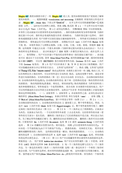
(一)、读取零件1.在读取零件之前,必须先设定好正确的单位(Main Menu/Tools/Settings)。
本演示零件的单位为毫米(mm)。
读取STL文件"Bad.stl" (Main Menu/File/Load Part)。
窗口中将显示零件(如图2-1):图2-1(二)、自动修改损坏的法向2.最初看上去,整个零件都是孔。
然而,当选中view工具栏中的Mode 标签下的flipped triangles后,整个零件就变得可视了,翻转过来的三角形用红色表示(图2-2)。
图2-23. 一个三角形定义了两种颜色:正面表示为灰色,反面表示为红色。
一个完好的零件外表看上去总是灰的。
完好的零件的内部(看零件的交叉部分)是红色的。
翻转的三角形显示了它们的背面而不是正面,所以显示为红色。
为了确定零件的截面正确与否,翻转的法向必须倒转过来。
翻转的三角形可以自动倒转,只要使用在fix 工具栏中的fix nomals选项图2-3或用automatic fixing 工具栏里的选项。
图2-4若翻转后仍然为红色,则可能是:间隙(可以看到零件内部有红色);不应该是一个平面的地方(由于不当剪切产生的) ;重叠的表面;壳体的交叉处;程序没有翻转或翻转错误的三角形。
这些错误需要逐一解决:修改残留的错误。
(三)、自动修改损坏的边界4. 选择view 工具栏中的bad edges 选项。
所有的损坏的边界以黄色显示。
(图2-5)图2-5用户可以隐藏零件背后或零件内部的损坏边界。
要做到这一点,用户需要hidden line checkbox.用户可以从零件属性(按)中看到,该零件有11652条损坏边界和340条损坏轮廓。
5.每一个三角形的边都与且仅与一个三角形共边。
当一条边没有相邻三角形(三角形在间隙边缘)或一条边有多于一个相邻三角形时就会出错。
当产生损坏边界时,将对零件的阴影造成影响。
这些问题可以用缝合解决。
通常,强烈建议用户保存(Main Menu/File/Save As...)修复的中间结果,因为修改一个损坏的STL文件在多数情况下是一项反复尝试的工作。
尤其是缝合,当用很大的公差缝合时会破坏零件。
在本例中用0.1的公差来进行缝合(fix toolsheet/tab triangle fixer或tab automatic) 。
在Auto 标签中用户还可以看到一个反复参数。
图2-6在这种情况下程序会缝合五次(仅当用户按下按钮)。
要观察公差值的效果,用户可以使用不同的值,例如,0.001、0.01和0.05和其他数量级的公差。
察看属性栏。
现在零件还有364处损坏边界和10处损坏轮廓。
这些错误必须手动修复。
图2-7(四)、修改残留错误进一步修改将时将局部的错误看作是一个独立的单元来进行修改。
6. 用户可以对零件进行旋转,平移和缩放操作。
对零件进行如上操作直到获得同下面所示图片同样的视图:图2-87. 零件内部在1号处可见并标以红色。
孔由于太大而不能用自动修复来填满。
我们可以用fill this hole(Fix Toolsheet/Tab Triangle Fixer)。
在Magics 填充的孔的区域用绿色表示。
如果对填充感到满意那么就去除选中的标记unmark(Mark Toolbar)图2-9另一种填充孔的方法是自己在孔中用指令create画三角形。
画完三角形后必须缝合。
这时所画三角形就可与周围的三角形‘联结’起来。
8.两个红点(2号和3号处) 标是两个有翻转三角形的壳体。
这是一个两个壳体相交叉的例子。
在接下来的步骤里我们将用布尔运算把所有的相互贯穿的壳体组合起来。
用户可以用指令Toolbar) 来选择壳体。
要倒转法向相反的壳体,可以点击fix toolsheet/tab fix normals)。
9. 找到如4号所示的情况。
图2-10zoom放大4号区域。
图2-11倒转该壳体使其像先前一个壳体的样子。
10.接下来将解决的错误在下图中表示出来:图2-12现在将零件中间(偏右方)放大(No.5):红色的平面需要手动翻转。
我们只要用mark plane (Mark Toolbar)指令选中该平面,然后用指令(fix toolsheet/tab fix normals)翻转平面。
如果用户对修改表示满意,则可以用指令unmark(Mark Toolbar) 去除选中标记。
要去除表示错误边界的黄色多边形,可以用缝合指令stitching (fix toolsheet/tab triangle fixer) 。
如果错误边消失,则说明该部分的错误就全部修复了。
按按钮,可以看到现在只剩下101条错误边界和7条错误轮廓。
图2-1311. 接下来回到零件视图,并放大No.6处的局部错误图2-14如果用指令mark plane(Mark Toolbar),将会出现如下图所示的结果:图2-15有时候,用户会看到红色(或绿色)与灰色表面相交错的图形。
这就表示两个表面重叠在一起(两个表面彼此在另一个表面的上方)。
要修复重叠表面,可以删除其中一个表面,或删除所有表面并填补删除后所产生的孔。
建议在修复重叠表面时,删除所有表面(先选中然后用指令fixing toolsheet/triangle fixer tab删除选中表面)然后再用指令create triangle和/或fill hole填补产生的孔。
如果由于重叠表面产生了错误边界,可以使用mark bad edge功能。
图2-16删除选中的三角形,在解决重叠表面的问题。
图2-17局部错误No.7、No.8和No.9可以与No.6同样处理(都是重叠表面)。
这里必须选中错误边界并删除选中的三角形。
对于No.7和No.8这样就可以解决问题。
对于No.9必须再次选中错误边界并删除所选。
重叠表面种的所有三角形删除后留下一个孔。
用fill hole功能,就可以修复错误。
按属性按钮(),系统显示现在还有63处错误边界和3处错误轮廓。
12. 放大No.10处局部错误并使其位于窗口中部。
这处错误是错误修剪产生的平面。
图2-18CAD软件画了一个不应该有的表面。
红色表面应该完全删除。
最好采用俯视(如图a)。
要修复这处错误应该删除这个平面。
图2-19要单独选中这个平面,必须调整平面选择参数plane selection parameter (Shift + ),出现下图所示的窗口:图2-20使用指令mark plane(Mark Toolbar) 选择三角形直到黄色轮廓被选中的三角形填满为止。
如果将平面选择参数设置过高,选中的部分会变大,删除后零件的细节部分会被删除,破坏了零件。
图2-21接下来删除选中的三角形Delete Marked (fix toolsheet/tab triangle fixer),出现下图所示:图2-22接下来填充fill hole(Fix Toolsheet/Tab Triangle Fixer)并取消选中unmark (Mark Toolbar)。
该处局部错误就可以修复了:图2-2313. 接下来要修补中间的红色圆(局部错误No.11)。
该处错误与No.5相似。
图2-24红色的圆必须手动翻转。
首先重新设定平面选择参数(Settings Menu / Plane Selection Parameters):图2-25接下来用指令mark plane (Mark Toolbar)选择平面并翻转选中部分(fixtoolsheet/tab fix normals)。
用缝合指令stitching (fix toolsheet/tab triangle fixer) 以公差0.1毫米删除表示错误边界的黄线。
当错误边界消除后,该处错误就被修复了图2-26要结束修复,可以用高公差缝合来消除剩余错误。
在此再次建议在缝合前先将结果保存为一个单独的文件。
14. 可以使用属性properties指令检查是否所有的局部错误都修复了。
如果错误边界和错误轮廓都为零,那么修复阶段的工作就结束了。
图2-27(五)、组合壳体15.在属性对话框里(),如果按下Analyze按钮,将会看到该零件有6个壳体。