Pajek操作手册
pajek时间网络使用方法
pajek时间网络使用教程时间网络(temporal network)分为两种类型一种是Time Events,在某个时间点发生改变;另一种是time intervals,在某个时间段网络状态维持不变。
文件后缀。
tim。
文件显示时间网络以lin_rel4。
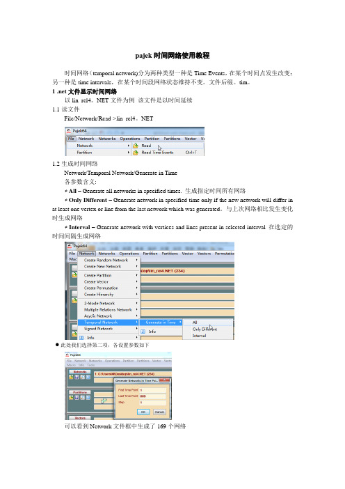
NET文件为例该文件是以时间延续1.1读文件File/Network/Read->lin_rel4。
NET1.2生成时间网络Network/Temporal Network/Generate in Time各参数含义:∗All – Generate all networks in specified times. 生成指定时间所有网络∗Only Different – Generate network in specified time only if the new network will differ in at least one vertex or line from the last network which was generated。
与上次网络相比发生变化时生成网络∗Interval – Generate network with vertices and lines present in selected interval 在选定的时间间隔生成网络此处我们选择第二项,各设置参数如下可以看到Network文件框中生成了169个网络每个网络就代表了该时刻网络的结构状态。
1.3绘制网络(1)选择从第二个网络开始(其实这是时间网络的初始网络),选择Draw/Network(2)点击Previous和Next可以动态绘制各时间节点的网络2.tim文件显示时间网络2.1读取时间文件File/Network/Read Time Events—>carlyle.tim2.2生成时间网络与1.2相同2.3绘制网络与1。
3相同参考文献:1 官网start with pajek教程http://mrvar。
pajek中文使用手册

Pajek分析和可视化大型网络的程序参考手册List of commands with short explanatio nversion 1.16Vladimir Batagelj and Andrej Mrvar翻译:先红、一生有我、傻大师、沧海回眸、AndyChang、comp network、遥遥、大头、三叶草整理:饭团Ljubljana, October 4, 20061996, 2006 V. Batagelj, A. Mrvar. Free for noncommercial use.PdfLaTex version October 1, 2003Vladimir BatageljDepartment of Mathematics, FMF University of Ljubljana, Slovenia http://vlado.fmf.uni-lj.si/****************************.siAndrej MrvarFaculty of Social Sciences University of Ljubljana, Slovenia http://mrvar.fdv.uni-lj.si/***********************.si目录1.Paje k介绍 (1)2.数据对象 (3)3 主窗口工具栏 (7)3.1 File(文件) (7)3.2 N et(网络) (11)3.3 N ets(网) (26)3.4 Operation(操作) (28)3.5 Partitio n(分类) (34)3.6 Partitions(分类) (35)3.7 Vector(向量) (35)3.8 V ect ors(向量) (36)3.9 Permutation(排序) (37)3.10 Cluster(类) (37)3.11 Hierarchy(层次) (37)3.12 Options(选项) (38)3.13 Info(信息) (40)3.14 Tools(工具) (40)4 绘图窗口工具 (42)4.1 主窗口绘图工具 (42)4.2 Layout(布局) (42)4.3 Layers(图层) (43)4.4 GraphOn l y(仅图形) (44)4.5 Previous(退回到前一次操作) (44)4.6 Redraw(重绘) (44)4.7 N ext(下一步) (44)4.8 Options(选项) (45)4.9 Export (导出) (47)4.10 Spin(旋转) (49)4.11 Mo ve(移动) (49)4.12 Info (信息) (49)5 Exports to E PS/SVG/VRML (50)5.1 Defaults (默认值) (50)5.2 Parameters in EPS,SVG and VRML Defaults Window(在EPS/SVG/VRML默认窗口中的参数) (50)5.3 Exporting Pictures to EPS/SVG —在输入文件中定义参数 (52)6 在Pajek中使用Macros(宏) (57)6.1 什么是Macro(宏)? (57)6.2 怎样标明一段宏? (57)6.3 如何运行宏? (57)6.4 例子 (57)6.5 重复最后的命令 (57)附加信息 (59)希望对使用Pajek 进行网络分析有一个概览,请阅读NICTA 工作室的幻灯片:Batagelj V.: Workshop on Network Analysis, Sydney, Australia: 14th to 17th June 2005; at Nicta (National ICT Australia). http://vlado.fmf.uni-lj.si/pub/networks/doc/#NICTA2.数据对象Pajek 是专门用来分析大型网络(含有成百上千个结点)的专用程序。
pajek使用手册

pajek使用手册Pajek使用手册1:简介1.1 Pajek是什么?1.2 Pajek的特点和优势1.3 Pajek的主要应用领域2:安装与配置2.1 和安装Pajek2.2 配置Pajek的环境变量2.3 打开Pajek界面3:数据导入与导出3.1 导入网络数据3.2 导入节点属性数据3.3 导入边属性数据3.4 导出网络数据3.5 导出分析结果4:基本操作4.1 创建新项目4.2 打开已有项目4.3 添加、删除和编辑节点4.4 添加、删除和编辑边4.5 设置节点和边属性4.6 图形操作:缩放、平移、旋转和放大 4.7 保存和关闭项目5:网络分析5.1 度分布分析5.2 群聚系数分析5.3 中心性分析5.4 社区检测算法5.5 强连通分量分析5.6 可视化网络分析结果5.7 导出分析结果数据6:高级功能6.1 模型拟合与预测6.2 动态网络分析6.3 多网络拓扑分析6.4 插件和扩展功能7:常见问题与解决方案7.1 Pajek运行缓慢怎么办?7.2 如何导入大规模网络数据?7.3 如何处理缺失数据?7.4 如何解释分析结果?8:附件本文档附带的附件包括演示数据、示例项目和额外资料,以帮助读者更好地理解和运用Pajek。
9:法律名词及注释- 知识产权:指人们在创作上所享有的权益。
- 数据隐私:指对个人或组织的数据进行保护,防止未经授权的访问和使用。
- 著作权:指对文学、艺术作品享有的独占权利。
- 许可证:指授权他人使用某一产品或服务的合法凭证。
注:本文档仅供参考使用,未经许可不得用于商业目的。
pajek 中文使用手册

Pajek分析和可视化大型网络的程序参考手册List of commands with short explanationversion 1.16Vladimir Batagelj and Andrej Mrvar翻译:先红、一生有我、傻大师、沧海回眸、AndyChang、comp network、遥遥、大头、三叶草整理:饭团Ljubljana, October 4, 20061996, 2006 V. Batagelj, A. Mrvar. Free for noncommercial use.PdfLaTex version October 1, 2003Vladimir BatageljDepartment of Mathematics, FMF University of Ljubljana, Slovenia http://vlado.fmf.uni-lj.si/ vladimir.batagelj@fmf.uni-lj.siAndrej MrvarFaculty of Social Sciences University of Ljubljana, Slovenia http://mrvar.fdv.uni-lj.si/ andrej.mrvar@fdv.uni-lj.si目录1.Pajek介绍 (1)2.数据对象 (3)3 主窗口工具栏 (7)3.1 File(文件) (7)3.2 Net(网络) (11)3.3 Nets(网) (26)3.4 Operation(操作) (28)3.5 Partition(分类) (34)3.6 Partitions(分类) (35)3.7 Vector(向量) (35)3.8 Vectors(向量) (36)3.9 Permutation(排序) (37)3.10 Cluster(类) (37)3.11 Hierarchy(层次) (37)3.12 Options(选项) (38)3.13 Info(信息) (40)3.14 Tools(工具) (40)4 绘图窗口工具 (42)4.1 主窗口绘图工具 (42)4.2 Layout(布局) (42)4.3 Layers(图层) (43)4.4 GraphOnly(仅图形) (44)4.5 Previous(退回到前一次操作) (44)4.6 Redraw(重绘) (44)4.7 Next(下一步) (44)4.8 Options(选项) (45)4.9 Export (导出) (47)4.10 Spin(旋转) (49)4.11 Move(移动) (49)4.12 Info (信息) (49)5 Exports to EPS/SVG/VRML (50)5.1 Defaults (默认值) (50)5.2 Parameters in EPS,SVG and VRML Defaults Window(在EPS/SVG/VRML默认窗口中的参数) (50)5.3 Exporting Pictures to EPS/SVG — 在输入文件中定义参数 (52)6 在Pajek中使用Macros(宏) (57)6.1 什么是Macro(宏)? (57)6.2 怎样标明一段宏? (57)6.3 如何运行宏? (57)6.4 例子 (57)6.5 重复最后的命令 (57)附加信息 (59)1.Pajek介绍Pajek 运行在Windows环境,用于带上千及至数百万个结点大型网络的分析和可视化操作。
派贝克服装CAD操作手册2009

目录目录 (1)第一章系统介绍 (3)第一节派贝克®(PAYBACK)服装CAD系统简介 (3)第二节派贝克®(PAYBACK)服装CAD系统制作流程 (3)第三节派贝克®(PAYBACK)服装CAD系统的价值 (4)第二章软件操作说明(基础编) (5)第一节菜单栏介绍 (5)一.文件 (5)二.素材库 (5)三.输入 (7)四.系统设置 (9)五.尺码表 (11)第二节纸样中心 (12)一.纸样中心常用工具 (12)二.纸样中心专用工具 (15)I.画线工具组: (15)II.求点工具组: (18)III.专用工具组 (19)IV.点线编辑工具组 (21)V.省褶工具组; (23)VI.生成裁片 (26)第三节裁片中心 (26)一.裁片中心常用工具 (26)二.裁片中心专用工具 (29)I.裁片标识 (29)II.工艺线 (31)III.裁片分割 (32)IV.褶裥 (33)V.旋转修整 (34)VI.放码 (35)第四节排料中心 (38)一.设置 (38)二.排料 (39)三.显示 (40)四.检测 (41)五.清除 (41)六.对条格 (41)七.排料报告 (41)八.其它 (42)九.裁片区 (43)十.混排 (44)第五节打印输出 (44)一.绘图仪输出 (44)二.切割机输出 (46)三.打印机输出 (46)第六节文件格式转换 (47)一.PLT格式文件 (47)二.DXF格式文件 (47)I.打开DXF格式文件 (47)II.保存DXF格式文件 (47)三.裁床格式文件 (47)第七节帮助 (48)一.主题 (48)二.快捷键列表 (48)I.文件处理快捷键 (48)II.纸样中心快捷键 (48)III.显示快捷键 (48)IV.裁片中心快捷键 (49)V.排料中心快捷键 (49)三.关于 (49)第三章智能模式(高级编) (50)第一节纸样设计 (50)一.绘图功能 (50)二.编辑功能 (52)三.特殊功能 (55)四.右键菜单 (57)第二节裁片处理 (58)一.缝边标记 (58)二.缝角处理 (60)三.内部线及工艺线设置 (61)四.裁片分割 (62)五.移动裁片 (62)六.点放码 (62)七.右键菜单功能 (65)八.空白处右键功能 (67)第三节快捷键功能 (69)第四章实例 (69)第一节女短裙 (69)第二节女裤 (73)第三节女衬衫 (81)第四节八片开身西服 (86)第一章系统介绍第一节派贝克®(payback)服装CAD系统简介由上海千派服装科技有限公司最新推出的派贝克®(payback)智能服装CAD系统是至今为止智能化程度最高的服装CAD系统。
帕克双设点控制器操作手册说明书

Cylinder Division 1000 6th Street East Owen Sound, Ontario Canada N4K 5P1(519) 376-2691Cylinder Division (U.S.A)500 South Wolf Road Des Plaines, IL 60016(847) 298-2400Service Bulletin 0971-G-B2Series SRX Dual Set Point Controller Operation ManualIssued: August 2002Supersedes: NoneSeries SRX – Dual Set Point Controller Operation ManualThe Parker Dual Set Point Controller relies on information provided by the position feedback sensor located inside the cylinder. The position sensor is a Linear Resistive Transducer (LRT) that acts as a voltage divider when a DC voltage is applied to it. The feedback signal produced by the LRT is dependent on the voltage input supplied. When a DC voltage is applied to the LRT, a relative output voltage (relative to piston position) is produced and sent back to the controller.There are four models available (see Figure 1). Each controller has two relay outputs whose on/off points are adjustable for different application needs.Model Number Input Power Scalable Output1493440002120 VAC 0-10 VDC 1493440003120 VAC 4-20 mA 149344000412-24 VDC 0-10 VDC 149344000512-24 VDC4-20 mAFigure 1. Dual Set Point Controller ModelsEach controller is equipped with two adjustable relay outputs that act as adjustable limit switches. These outputs come with Normally Closed (NC) and Normally Open (NO) contacts. If more than two outputs are needed, up to three controllers may be slaved off of one master unit.Standard electrical connections for each controller are shown in Figure 2. Detailed instructions for connecting power and the LRT are shown in Figures 3 and 4, respectively.Figure 3. Power ConnectionsFigure 4. LRT ConnectionsFigure 2. Standard Electrical ConnectionsStandard electrical connections produce standard output operation. Standard output operation is defined by ananalog output signal that is at a minimum when the cylinder is fully retracted, and increases linearly to a maximum when the cylinder is fully extended. Figure 5 on the following page shows ideal voltage output versus cylindertravel and the corresponding relay output actions.Figure 5. Output ConfigurationsThe outputs from Relay 1 and Relay 2 are adjustable over the entire range of cylinder movement. Set-Point 1 can be adjusted beyond Set-Point 2. If the Continuous Cycle Mode is used, Set-Point 2 must be adjusted beyond Set-Point 1. See Figure 5. Figures 6-A thru 6-D show relay contact configurations for standard operating modes.Figure 6-AFigure 6-BFigure 6-CFigure 6-DIndependent Relay ModeNon-Inverted OperationInstall load to Normally Open (NO) side of the relays. Pin 10 for Relay 1 and Pin 13 for Relay 2. Refer to Figure 2for electrical connections. When the load is connected to the NO sides of the relays, the output will turn on when the analog output is greater than its set point and turn off when the analog output is less than its set point.Inverted OperationInstall load to Normally Closed (NC) side of the relays. Pin 9 for Relay 1 and Pin 12 for Relay 2. Refer to Figure 2for electrical connections. When the load is connected to the NC sides of the relays, the output will turn off when the analog output is greater than its set point and turn on when the analog output is less than its set point.Limit Switch OperationInstall load to one Normally Closed (NC) relay lead and one Normally Open (NO) relay lead. Pin 9 for Relay 1 and Pin 13 for Relay 2. Refer to Figure 2 for electrical connections. This arrangement turns on Relay 1 when the analog output is less than Set-Point 1, and turns on Relay 2 when the analog output is greater than Set-Point 2.Continuous Cycle ModeInstall load to Normally Open (NO) side of the relays. Pin 10 for Relay 1 and Pin 13 for Relay 2. Refer to Figure 2 for electrical connections. When the load is connected to the NO sides of the relays, the output will turn on when the analog output is greater than its set point, and turn off when the analog output is less than its set point.As one output turns on, the other turns off and vice-versa. This mode of operation allows for continuous cyclingof a cylinder between two adjustable limits. Set-Point 1 control potentiometer is used to set the inner limit andSet-Point 2 control potentiometer is used to set the outer limit. Set-Point 1 must be less than Set-Point 2.To activate the Continuous Cycle Mode, move Jumper 1 to Position B (see Figure 7). This enables the Continuous Cycle Mode and disables the Independent Relay Mode.As illustrated in Figure 7, the Independent Relay Mode of operation is factory enabled with Jumper 1 in Position A.Position A Independent Relay ModePosition B Continuous Cycle ModeFigure 7. Operating Mode Selection Using Jumper 1Jumper 1 is located on the bottom side of the circuit board. The jumper can be accessed by removing all four corner screws of the controller. At this point, the cover and circuit board should come out of the base. Turn the cover and circuit board over so that the bottom of the circuit board is visible. The jumper is located in the upper right-hand corner. The jumper can be moved into Position A or B by pulling up on the black jumper and placing it over the appropriate pins as illustrated in Figure 7.When the jumper is located in the desired position, place the circuit board and cover back into the base and tighten all four corner screws.Setting the Switch Points of OutputAt this point, make sure all electrical connections have been made properly and apply power to the controller. Each controller has the same controls and uses the same set-up procedure.To set the switch point of output 1:1.Turn Set-Point potentiometer 1 (Set 1) fully counter-clockwise.2.Move the cylinder piston to the desired position where output 1 should switch on and off.3.Observe Set-Point 1 LED.4.Rotate Set-Point potentiometer 1 (Set 1) clockwise until Set-Point 1 LED just changes state (on to off orvice-versa).To set the switch point of output 2:1.Turn Set-Point potentiometer 2 (Set 2) fully clockwise.2.Move the cylinder piston to the desired position where output 2 should switch on and off.3.Observe Set-Point 2 LED.4.Rotate Set-Point potentiometer 2 (Set 2) counter-clockwise until Set-Point 2 LED just changes state.Scalable OutputThere are two different types of output: 0V to 10V and 4mA to 20mA. Each type is available for AC or DC power.Output Boundaries and ActionsStandard output operation produces minimum analog output at minimum cylinder extension and maximum analog output at maximum extension. Figure 8 plots ideal analog output versus cylinder travel.For some applications, it may be desirable to reverse this operation and have maximum analog output at minimum extension and minimum output at maximum extension. This can be achieved by switching the wires at Pins 3 and 5 of the control unit as shown before in Figure 2. The resulting output is reversed and is illustrated in Figure 9.Figure 8. Standard Analog Output Figure 9. Reversed Analog OutputScaling the OutputScaling is a feature that allows a controllers output boundaries to be adjusted to individual application needs.The minimum analog output point (offset) is adjustable, as well as the distance from the minimum output that the cylinder must travel until maximum analog output is achieved. This distance is the span. The output boundaries provide minimum and maximum output with linear output between the two limits.Figure 10 illustrates the allowable output adjustment range for standard output operation as a percentage of full cylinder extension. Figure 11 illustrates the allowable output range for reversed output operation. The shaded region of each graph represents the allowable area where full analog output can be achieved.Figure 10. Standard Output Range Figure 11. Reversed Output RangeThe figures illustrate two important facts:1.The maximum offset is 50% of the cylinder stroke.This is the right boundary.2.The minimum span is 50% of the cylinder stroke.This is the left boundary.Figures 12 and 13illustrate acceptable and unacceptable calibrations, respectively, for a cylinder with a 12" stroke.Line #Offset Max. Position Span10"12"12"22"10"8"35"11"6"Figure 12. Acceptable Calibration Schemes Line #Offset Max. Position Span12"7"5"24"8"4"34"Figure 13. Unacceptable Calibration SchemesThe setting of the analog output is accomplished by adjusting the potentiometers “OFFSET” and “SPAN”.ØThe “OFFSET” adjustment is used to set the desired minimum analog output point.ØThe “SPAN” adjustment is used to set the desired maximum analog output point.Clockwise = Output Increases Counterclockwise = Output DecreasesSetting Scalable OutputThe procedure used to set the analog output is as follows:Setting the Offset (minimum output point)1.Move the cylinder piston to the minimum position desired.2.On 0-10 VDC controllers: Place a voltmeter across Pins 6 (Analog Out) and 7 (Analog Gnd).3.On 4-20 mA controllers: Place an ammeter in series with the load to be driven. Current sources from Pin 6(Analog Out) and returns to Pin 7 (Analog Gnd).4.Adjust the offset potentiometer until the desired minimum output is reached. Setting the Span (distance between minimum and maximum analog output)1.Move the cylinder piston to the maximum position desired.2.On 0-10 VDC controllers: Place a voltmeter across Pins 6 (Analog Out) and 7 (Analog Gnd).3.On 4-20 mA controllers: Place an ammeter in series with the load to be driven. Current sources from Pin 6(Analog Out) and returns to Pin 7 (Analog Gnd).4.Adjust the span potentiometer until the desired output is reached.Repeat steps 1 and 2 respectively in order to fine tune the retract and extend output signals.This completes the scaling procedure. At this point, the controller is set up and ready for use.TroubleshootingThe controllers operate on very fundamental principles, which greatly reduce the likelihood of problems. If a problem arises, there are several items to check before consulting your distributor.1.Verify that all connections have been made properly.2.Verify that the required power source is working.3.Verify that the LRT output (0 to 10 VDC) at Pin 4 is changing with cylinder movement.If all of these check out, contact the Cylinder Division for further assistance.System SpecificationsEnclosure Dimensions: 1.31” H x 5.56” W x 3.31”DShipping Weight: 0.80 lbsPower Input Requirements: AC Models 120 V 60 Hz 0.1 AmpsDC Models 12-24 VDC0.1 AmpsInput Fuse: 0.25 AmpsOutput Specification – Set Points:Relay (2) 6 Amps @ 28 VDC6 Amps @ 120/300 VACOutput Specifications: 0-10 VDC, 1 mA MAX output current into 10kΩMIN impedance4-20 mA, into 500Ω MAX impedanceMaximum Zero Offset: 50% of cylinder strokeMinimum Span Range: 50% of cylinder strokeElectronics T emperature Range: 40°F to 160°FFigure 14. Controller DimensionsApplication - Continuous Cycling Using a Three-Position Valve Desired Result: A cylinder/system that will cycle between two adjustable limits.Equipment:Parker Dual Set Point Controller (Continuous Cycle Mode)Double solenoid (24VDC) 3 position valveSeries SRX CylinderFigure 15. Continuous Cycling Electrical Connections Figure 15 illustrates the internal connections of a typical application. Movement of the cylinder is controlled by the double solenoid three position valve. For any movement to occur, an output must be activated.In this application, Relay 1 is used to retract the cylinder and Relay 2 is used to extend the cylinder.By using the Continuous Cycle Mode of the controller, the cylinder will continuously cyclebetween the two set point limits.Figure 16. Output ConfigurationsFigure 16 illustrates the output actions and theideal analog output signal versus cylinder pistontravel.The analog signal can be monitored at Pins 6and 7 (Analog Out and Analog Gnd). Controlpotentiometer 1 (Set 1) is used to adjust Set-Point 1 and control potentiometer 2 (Set 2) isused to adjust Set-Point 2.Relay 1 will be activated while the cylinder isretracting to Set-Point 1. When the pistonreaches Set-Point 1, Relay 1 will deactivate andRelay 2 will be activated.Relay 2 will cause the cylinder to extend untilthe piston reaches Set-Point 2, where Relay 1will activate and the process will repeat.Application – Independent Mode Limit Switch OperationDesired Result: A cylinder/system that will activate a warning light if the system is operating outside of the desired limits.Equipment:Parker Dual Set Point Controller (Independent Relay Mode)Motion Control System (e.g. PLC, Valves, Warning Light)Series SRX CylinderFigure 17. Limit Switch Electrical Connections Figure 17 illustrates the internal connections of a typical limit switch application. Movement of the cylinder is controlled by the Motion Control System.By using the Independent Relay Mode with Limit Switch Operation, the controller will monitor the position of the cylinder. As long as the cylinder is within the two set point limits, the warning light will remain off. But if the cylinder moves outside either limit point, the warning light will activate.Figure 18. Output Configurations Figure 18 illustrates the output actions and the ideal analog output signal versus cylinder piston travel.Control potentiometer 1 (Set 1) is used to adjust Set-Point 1 and control potentiometer 2 (Set 2) is used to adjust Set-Point 2.Relay 1 output will be activated when the cylinder retracts beyond Set-Point 1.Relay 2 output will be activated when thecylinder extends beyond Set-Point 2.。
Parker产品操作手册说明书

Operating ManualThank you for your choice of Parker product. Please read this operating manual carefully and use the product correctly. Keep this operating manual in case questions arise about this product in the future. If this operating manual becomes unreadable or lost, consult our distributors or Parker sales offices.For Safety UseThe following safety precautions are provided to prevent damage and injury to personnel and to provide instructions on the correct usage of this product. These precautions are classified into 3 categories: “CAUTION”, ”WARNING”, and “DANGER” according to the severity of possible injury or damage and the likelihood of such injury or damage. Be sure to comply with all precautions. Also comply with safety regulations such as JIS B 8370(*1), Industrial Safety and Health Law, and High Pressure Gas Safety Law, and ISO 4414(*2).Danger:Indicates an impeding hazardous situation whichmay arise due to improper handling or operationand could result in serious personal injury or death.Warning:Indicates a potentially hazardous situation which may arise due to improper handling or operationand could result in serious personal injury or death.Caution:Indicates a potentially hazardous situation which may arise due to improper handling or operationand could result in personal injury or property-damage-only accidents.*1 JIS B8370 : General Rules for Pneumatic Systems*2 ISO 4414: Pneumatic fluid power recommendations for the application of equipment totransmission control system.● This product is designed for air blowgun.Do not use it for other purposes.● Use compressed air from an air compressor.Do not use air from a high pressure tank or any other gas.● Do not blow air from air blowgun towards personnel or animals.Direct air blow or substance blown by air blow can potentially cause injury for humans or animals.● Wear safety glasses and ear plugs.Regardless of the use of this product, wear safety glasses and earplugs when operating an air blowgun. Without proper protection, injury to eyes due to blown dust or noise induced deafness would be potentially caused.● Do not disassemble or modify this product.Disassembling or modification may causes safety accidents in addition to operation failure.● Attach a pipe fitting or joint properly.If a pipe fitting or joint are attached improperly, it may cause danger such as hose whip due to unplugged piping. Confirm the connection of hose, tube or coupler joint is tight as well as the connection to this product prior to use.● Do not use for medical equipment or cooking equipmentThis product contains a small amount of lubricant. If there is concern for contamination due to lubricant, do not use.SpecificationsFluid Compressed air Pressure Range 0.35 to 0.8MPaMaximum Flow *1 1300L/min (@0.5MPa) Ambient Temperature*210 to 50℃ Pulse Adjustment Range5 to 15HzPort SizeIN Rc1/4OUTR1/4Weight155g*1 “Maximum Flow” in this case is the flow capacity of this product,and actual flow consumption is depending on the attached air blowgun.*2 If the temperature is under the specified temperature, pulse blowmay be unstable. In this case, please use it as continuous blow temporally for a while to reach specified temperature. This product works correctly within the specified ambient temperature.Connection≪取付例≫1. Before Piping, thoroughly flush the inside of each pipe toremove chips, machining oil, and dust etc. If sealing tape is used for the thread, leave 1.5 to 2 thread turns unwrapped. Do not use liquid sealant. It has possibility to contaminate the product and may cause malfunction.Push-in fitting or joint such as coupler(Sold Separately) Air Saver Unit for Air Blowgun“Air Saver Module” HASV08R9IM-E009-aIssued :Jan.14.2016Air blowgun“Air Saver Module”HASV08R Reference blowgun:Parker LegrisPart Number: 0659 00 13(Sold Separately)WarningCaution<Example of attachment>2.When installing piping or a joint, prevent contamination of chips or sealing agent. Also tightening torque should be within the range indicated below.Port Size Tightening Torque (N ・m)R ・Rc1/412 to 143.An air filter (Nominal filtration rating of 5 micron or smaller) must be placed upstream of piping. There is no need for additional lubrication.4. Attach the piping towards the direction of air flow described on the body. If it is opposite direction, this product does not work.5.This product must be attached directly to an air blow gun. If connected with any part such as coupler, it has the possibility to decrease the capability due to pressure loss.6.This product is not water & drip proof. Do not install this product in a place with direct water contact (rain, etc). Also install this product in a place without dew condensation or direct sunlight.Product Function[Pulse Adjustment Screw]This is a throttle valve for pulse ON time adjustment (Approx.5 to 15 Hz). When tightening this screw clockwise with flat-bladedscrewdriver, the air ON time will be longer. When loosening the screw counter clockwise, the air ON time will be shorter. The air OFF time is fixed for approx. 30ms. Adjust the air ON time in accordance with using air blowgun or object. Control angle is approx. single rotation of the screw. When tightening at the end of clockwise, it will stop air output, however it is not malfunction.[Pulse/ Continuous Switching Button]Press this button when requiring continuous blow. When pushing this button, air blows continuously. To keep continuous blow, press this button and turn the button 90 degrees. To release from this mode, press this button and turn counter clockwise for pulse blow mode.DimensionsNotes for Usage● Discharge drain from upstream air filter periodically. If periodic drain discharge is difficult, Parker recommends setting up an air filter with automatic drain.● Maintenance compressor periodically. If sludge, which isproduced in compressor oil, enters pneumatic equipment, it will cause operation failure of pneumatic equipment. Coalescing filter removes oil and sludge which cannot be removed by air filter. Parker recommends setting up a coalescing filter.Effect of Pulse BlowIn many factories, air blow accounts for more than 50% of total compressed air consumption. Pulse blow can be a measure forsaving energy by reducing the consumption of compressed air while maintaining the same capability of air blow operation.・Hole machining, tap, chip removing of complex shape work ・Removing stuck dust or viscous liquid ・Blowing at narrow space・Reducing load of compressor ・Energy saving activityPulse blow is especially effective for works listed above, however it is not for all applications. There is a possibility to reduce the removal effectiveness depending on the air blowgun. Parker recommends attaching to an air blowgun that has nozzle diameter bigger than I.D.2mm and low pressure loss.Also, for the case of using reduced pressure for air supply, installing this product without regulator enables a low energy loss circuit, which provides improved blow effectiveness compared to the current circuit.Kuroda Pneumatics Ltd(Parker Hannifin Automation Division Japan)10243 Kamakazu, Asahi city, Chiba 289-2505, JapanE-mail:********************10HzWhen screwing, seal tape may enters the product and cause malfunction.Leave space of 1.5 -2 turnsUse half width seal tape. It may reduce cost as well. Cut with knife.(Not good)(Good) Air Blow Gun Connecting Port (R1/4)Pulse Control Trimmer[Note] ● Please contact our distributors or Parker for after-sales service. ● Please keep this operating manual.15HzPressure Supply Port (Rc1/4)Vent HolePulse/ContinuousSwitching ButtonFlow Flow Current Circuit Pulse Blow A i r C o n s u m p t i o n L /m i nA i r C o n s u m p t i o n L /m i nTime (sec)Time (sec) Pulse Adjustment Screw (ON Time Control)Pulse/ Continuous Switching button Time Time。
Pajek操作手册

关键词:复杂网络,可视化,抽象化,有向图,无向图,权值
EMULATOR OF COMPLEX NETWORK
ABSTRACT
The idea of complex network, with thousands of vertices and lines, have been widely applied in many different areas, including computer, biology, physics and social science, to name but a few. Although the types of complex networks are innumerable, all of them can be described by a common model, which is known as graph. Based on graphs and using six data structures, Pajek, which is very efficient and humanized, is a program designed for the emulation of complex network. The basic set of efficient algorithms are implemented in it to analyze the topology of complex networks, including analysis of the local nature of vertices and lines, abstraction to get a global view of network, transformation between different types of networks, generating random networks and so on. Pajek provide the user with some powerful visualization tools on a three-dimensioned reference frame. The user can further improve the picture manually or automatically by moving vertices or spin. Moreover, we can define an often
- 1、下载文档前请自行甄别文档内容的完整性,平台不提供额外的编辑、内容补充、找答案等附加服务。
- 2、"仅部分预览"的文档,不可在线预览部分如存在完整性等问题,可反馈申请退款(可完整预览的文档不适用该条件!)。
- 3、如文档侵犯您的权益,请联系客服反馈,我们会尽快为您处理(人工客服工作时间:9:00-18:30)。
2 Pajek 的主要特点
简单的说,Pajek 的特点主要表现在三个方面。在本章的三小节中将一一简单介绍。
2.1 计算的快速性
Pajek 为用户提供了一整套快速有效的算法,可用于分析大型的(节点书数以万计的)
一般来说,图的分类有两种方法。根据图中的边是否具有方向性,可以将图分为有向图 和无向图两种。实际上,当我们忽略边的方向的时候,或者反过来看认为任何一条边都是双 向的时候,有向图就成为无向图。因此,关于无向图的所有性质都可以在有向图中研究。另 外,根据图中是否考虑各条边的权重,可以将它分为有权图和无权图。同样地,如果将有权 图的各边权值都设为 1,有权图就称为无权图。因此,关于无权图的所有性质也可以在有权
used sequence of elementary operations as a macro and run it as a single command. Using systems of macros, Pajek is adapted to special groups of users. In this article, with some typical examples, the main applications of Pajek are discussed to analysis the topology of complex networks.
复杂网络仿真平台
摘要
复杂网络的概念已经在计算机、生物、物理以及社会科学等各个领域中得到广泛的应用。 尽管复杂网络的类型举不胜举,但是所有的复杂网络都可以用共同的模型——图来描述。 Pajek 以网络图的模型为基础,以六种数据类型为形式,以其快速有效性和人性化的特点, 为复杂网络的分析提供了一个仿真平台。它集成了一系列快速有效的算法用于分析复杂网络 的拓扑结构,包括从局部的角度分析网络节点和边的性质、利用抽象化的手段分析网络的全 局结构、实现各种类型网络图之间的相互转换以及随即图的生成等。Pajek 利用一个三维的 可视化界面,为用户提供了一系列可视化工具。允许用户通过手动或者自动的调节节点位置、 旋转网络图等方法,从视觉的角度直观地分析网络模型。此外,Pajek 中的宏文件允许用户 将一系列常用的操作保存为一个文件,从而能够有效地满足各种类型用户的不同需求。本文 将结合具体的实例,分章节讨论 Pajek 在分析复杂网络拓扑结构中的应用。
6.4.1 1-模与 2-模复杂网络的概念 28 6.4.2 利用 Pajek 实现 2-模到 1-模复杂网络的转换 30 6.4.3 其他附属选项 31 7 利用 Pajek 生成复杂网络 34 7.1 生成复杂网络 34 7.2 生成 ER 随机网络 35 7.3 生成无尺度(scale-free)复杂网络 35 8 Pajek 的可视化 37 8.1 复杂网络图的绘制 37 8.1.1 绘制复杂网络图 37 8.1.2 绘制不同类节点的复杂网络图 37 8.1.3 绘制不同大小节点的复杂网络图 38 8.1.4 绘制不同权值的边的复杂网络图 38 8.2 调整复杂网络图的布局 38 8.3 复杂网络图的旋转 41 9 Pajek 中的宏 42 9.1 宏的作用 42 9.2 宏的定义 42 9.3 宏的使用 42 9.4 宏的应用实例 42 10 结论 44
1.2 Pajek 的产生背景
与一般计算机图的结构相比,复杂网络的复杂性最主要表现在节点数目庞大,通常达到 几千甚至几万个。比如,一个大型的家谱图,它的节点数(即人数)可以达到一万个。另外, 一个高分子的结构图中,通常也包含几千个原子。因此,复杂网络的结构比一般的计算机图 的结构要复杂得多。目前,虽然已经存在不少算法来对复杂网络的这种拓扑结构进行分析, 但它们通常都是基于复杂网络的矩阵表达形式,因而非常耗时耗空间,它们仅仅适用于中等 规模(即节点数为几百)的网络。因此,当务之急就是需要一种快速有效的软件来分析和仿 真复杂网络。Pajek 就是这样一种软件[13]。
1 引言
1.1 复杂网络的ห้องสมุดไป่ตู้本概念以及研究历史
近几年来,复杂网络的研究正处于蓬勃发展的阶段[1,2],其思想已经充斥到科学和社 会的每一个角落。复杂网络可以用来描述人与人之间的社会关系[3],物种之间的捕食关系 [4],计算机之间的网络联接[5],词与词之间的语义联系[6],科学家之间的合作关系[7],蛋 白质之间的相互作用 [8],科研文章之间的引用关系[9] 以及网页的链接结构[9]等等。总之, 从因特网到万维网,从生物体的结构网络到动物之间的食物链,从人体的神经网络到社会关 系网络等等,可以说,复杂网络,无处不在。复杂网络的研究正渗透到物理、生物甚至社会 学科等各个领域,因而,复杂网络的定性和定量研究已经成为当今科学的一大主题。
每一个系统中的复杂网络都有其自身的特殊性质,有其紧密联系在一起的独特现象,有 其自身的演化机制,但是不同的复杂网络在其结构特征上都呈现出一定的共性[10]。研究复 杂网络的共性,首先需要一种描述这种不同类型复杂网络的共同数学模型。
复杂网络模型的研究,最早可以追溯到十八世纪,由伟大的数学家欧拉建立。欧拉所研 究的问题,就是起源于当时俄国的一个小镇,这个小镇中有一些河流,在此镇中一共建了 7 座桥,小镇的人希望找到一条行走路线,能够通过所有的桥,并且每座桥只能经过一次。当 时人们反复尝试也没有找到这样的路线,最后欧拉发现这样的路径是不存在的。他分析这个 问题基本的手段,就是把这个问题用一个抽象的图来表示。具体做法即把这些河流分割开的 四个陆地区域,每一个区域用一个结点来表示,而把桥梁当成连接这些结点的连线。这样一 种图的表示方法,就演变成为表述复杂网络一种共同的模型。比如对 Internet 而言,每一个 结点表示一个路由器,如果两个路由器之间直接通过光纤连接,则这两个节点就通过一条边 相连。以人类社会关系网络而言,每一个人就可以看成一个结点,两个人如果是朋友关系, 那么这两个人之间就有一条边直接相连。因此,尽管复杂网络的类型是千差万别的,但是它 们都可以用共同的模型——图描述出来[11]。
Keywords: complex network, visualization, abstraction, directed network, undirected network, weight
目录
1 引言 1 1.1 复杂网络的基本概念以及研究历史 1 1.2 Pajek 的产生背景 2 2 Pajek 的主要特点 3 2.1 计算的快速性 3 2.2 可视化 4 2.3 抽象化 4 3 Pajek 的数据结构 6 3.1 Network(网络) 6 3.2 Partition(分类) 9 3.3 Permutation(排序) 9 3.4 Cluster(类) 10 3.5 Hierarchy(层次) 10 3.6 Vector(向量) 10 4 利用 Pajek 分析复杂网络基本性质 12 4.1 度的计算 12 4.2 两点间的距离 13 4.2.1 两点间的最短路径 13 4.2.2 复杂网络的直径 15 4.2.3 K 步之内的路径 15 4.2.4 复杂网络的测地矩阵(Geometric Matrices) 15 4.3k 近邻(k-neighbors) 16 4.4 聚类系数 17 4.4.1 CC1--- 聚类系数 17 4.4.2 CC2--- 2 近邻聚类系数 19 5 利用 Pajek 分析复杂网络结构 20 5.1 复杂网络图的遍历 20 5.1.1 深度优先搜索遍历 20 5.1.2 广度优先搜索遍历 21 5.2 复杂网络图的核心(Core) 21 5.3 复杂网络图的连通分量(components) 23 5.4 复杂网络的关键路径 24 6 利用 Pajek 转换复杂网络 26 6.1 无向边与有向边的转换 26 6.1.1 有向边转换为无向边 26 6.1.2 无向边转换为有向边 26 6.2 改变复杂网络图的结构 26 6.2.1 添加节点 26 6.2.2 添加兄弟边(sibling edges) 27 6.2.3 删除边 27 6.3 复杂网络图的缩减 27 6.4 2-模到 1-模网络图的转换 28
1
图中研究。 利用图对复杂网络建模后,可以看到其结构具有很多相同的共性。例如关于顶点度值、
聚类系数、平均路径长度[12]的分析方法以及大量不同复杂网络中存在的相同的统计特征, 再如随机去点与选择性攻击对复杂网络结构的影响及其分析方法[10]。研究复杂网络的几何 性质,复杂网络的形成机制,复杂网络演化的统计规律,复杂网络上的模型性质,以及复杂 网络的结构稳定性,并把它与具体系统结合起来就是复杂网络研究的中心内容。
Pajek 在斯拉夫语中表示的意思是“蜘蛛”。众所周知,蜘蛛是生物中的织网高手,它编 织网络的能力令人叹为观止。而 Pajek 这个软件不仅为用户提供了一整套快速有效的用来分 析复杂网络的算法,而且还提供了一个可视化的界面。让用户可以从视觉的角度更加直观地 了解复杂网络的结构特性。
接下来的几个章节,第二章简单介绍了 Pajek 功能的三个主要特点;第三章中初步介绍 了 Pajek 的六种数据类型;第四章到第七章将结合复杂网络的拓扑结构特点详细分析 Pajek 的功能,并且给出具体的应用实例;第八章讨论了 Pajek 的可视化特点,从视觉的角度分析 复杂网络图的结构;第九章介绍了 Pajek 中宏文件的应用。
关键词:复杂网络,可视化,抽象化,有向图,无向图,权值
EMULATOR OF COMPLEX NETWORK
ABSTRACT
The idea of complex network, with thousands of vertices and lines, have been widely applied in many different areas, including computer, biology, physics and social science, to name but a few. Although the types of complex networks are innumerable, all of them can be described by a common model, which is known as graph. Based on graphs and using six data structures, Pajek, which is very efficient and humanized, is a program designed for the emulation of complex network. The basic set of efficient algorithms are implemented in it to analyze the topology of complex networks, including analysis of the local nature of vertices and lines, abstraction to get a global view of network, transformation between different types of networks, generating random networks and so on. Pajek provide the user with some powerful visualization tools on a three-dimensioned reference frame. The user can further improve the picture manually or automatically by moving vertices or spin. Moreover, we can define an often