燃油水寒宝产品说明书
水冷说明书ORION中文

外观
各部名称
外观
9
各部名称
操作板的名称及机能
操作板的名称及机能
①数字显示部 ②冷却器运转灯
③
冷却器运转开关
④
复位开关
⑤设定开关
⑥温度调节开关
测定水温显示(通常显示) 警报(错误)显示(闪烁)
灯亮:运转
灯灭:停止 在运转或停止冷却器时按动。
在解除警报(错误)时按动。
轻轻按动:可确认设定水温。 按 2 秒以上:可变更设定水温。 *在数字显示部显示设定水温,灯闪烁。 改变设定水温时按动。
接触到设备内部,会导致触电。
产品和机械室内,不要淋水。
而且不要用水洗,否则会导致触电或火灾等。
不要损坏或加工电源线
电源线上放置重物,或过热,或牵拉,或挤压,都会导致电源线损坏,从 而引发触电或火灾等。
异常是要停止运转,向销售店或专业人员咨询。
异常状态下继续运转,会导致触电或火灾等。
漏电断电器工作时,请向专业人员咨询。
(参照「■泵的运转方法」) 5.循环水槽的水,排掉配管内的空气,之后水压计指示上升,压力稳定下来。 6.在压力稳定之后,通过旁通阀,调整到使用压力。
(参照「■送水压力的调整」)
●水位的确认
●水槽即使满水,也有时混入空气。这时候启动冷却器,可能不能冷却。 ●水槽内装有溢流开关,水位达到设定以下时,数字显示为「E03」,发出警报信号。
压送泵水回路(冷却水排放口及旁通阀)的全封闭运转是严格禁止的。全封闭运转的话,压 力会超过 1.2MPa,会使过滤损坏,而且由于泵的故障及泵体发热,会导致配管变形和水的泄 露。 3.对开关频繁低进行 ON/OFF 操作,有可能引发故障。停机之后再启动时,请经过 3 分钟以上 时间。在 3 分钟以内启动运转的话,安全装置起保护作用,还会导致压缩机故障。 4.泵的空运行也是严格禁止的。水槽内必须加水,在确认水位之后再实施运转。 5.排水之际,请将冻结放置模式 OFF。因为泵的空运转会导致故障。 6.水要经常保持清洁,每一个月进行一次水回路检查。必要时,情换水。 (请参照「冷凝器过滤清扫」) 7.对冷凝器过滤,每一个月清扫一次。 (请参照「冷凝器过滤清扫」)
海洋燃油冷却系统-Alfa Laval高级冷却系统说明书

The ACS can integrate the Alfa Laval Fuel ConditioningModule (FCM) as well as any other booster system, on new buildings or ships in operation.Features and benefitsC ompliance with new fuel regulations ACS allows theoperators to:▪A chieve easy and full automated fuel changeover p rocedures▪H andle up to 3 different fuels▪P erform direct (HFO to MGO) and intermediate (HFO to MDO to MGO) fuel changeover procedureS afetyACS provides cutting edge control of variation in fuelt emperature and viscosity. This makes possible to achieve safe fuel changeover procedures by avoiding any thermal shock and any drop in fuel viscosity. I ntegration▪S eamless communication between ACS and FCM for automatic and reliable fuel changeover procedures▪F ull compatibility of ACS with any fuel conditioning m odule, even from other suppliersA utomation▪A CS is fully automated and easy to operate▪P ossibillity of full process control from remote panel▪F ull changeover procedure customization by controlling all process parametersV ersatility▪O ptional chiller unit available for the supply of proper cooling media to ACS▪P ossibility to develop ACS tailor made versions on requestKey componentsThe ACS scope of supply includes everything needed, with the exception of pipes and cables, to construct a complete fuel cooling system for newbuildings or to retrofit fuel supply systems on existing vessels.A CS CoolerThe ACS is equipped with a heat exchanger that usesfresh water or seawater as cooling media. The plate heatexchanger cooler type has high corrosion resistance, high efficiency and compact design.M ixing valveThis electrically operated three-way mixing valve regulates fuel temperature by partializing the amount of fuel flowing through the ACS cooler. The stepless flow adjustment allows a sharp temperature control of the light fuel, in order to provide a reliable t emperature ramp and final injection temperature.T emperature transmitterMounted on booster module or near the engine, thet emperature transmitter supplies data about fuelt emperature to the engine to the ACS control unit. C hangeover valvesThe ACS incorporates two main three-way changeover valves positioned at the fuel supply feed inlet and prior to the inlet of the ACS cooler. These are supplied according to the dimensions of the connected pipework. One more three-way changeover valve is available as an option to C ontrol systemACS operation is steered and monitored by a controlpanel, and can be equipped for different levels of remote control:▪ B asic – free contacts (only alarms and readings) ▪ E xtended – free contacts (change over start up andalarms and temperature readings) ▪ M odbus – full remote control through onboarda utoma tion systemM odularized assemblyACS is a compact and skid mounted unit, ready for a space saving installation on any booster system.C hiller unitACS is available with a chiller unit from our partner NOVENCO, with start / s top function integrated in the control panel.1. HFO and MGO day tank2. Three way changeover valve (V1)3. Pump strainers4. Supply pump5. Automatic backflushing filter6. Filter pressure drop switch7. Supply pressure control valve8. Flow transmitter9. Flow transmitter bypass10. Pressure transmitter, supply pump 11. Level switch12. Automatic de-aeration valve 13. Mixing tube14. Circulation pump 15. Heaters16. Pressure transmitter, circ. pump 17. Temperature sensor 18. Viscosity sensor19. Engine pressure control valve 20. Three way changeover valve (V2)21. ACS Cooler22. Three way mixing valve (V3)23. Temperature transmitter (TT2)24. Temperature transmitter (TT3)25. SPV Cooler26. Three way changeover valve (V4) 27. Heating media valve (V6)28. Cooling media valve (V7)Operating principleThe ACS operation is based on temperature adjustable s et p oint and viscosity control operated by FCM viscosity sensor.C hangeover from HFO to MGOTo initiate the switch from HFO to MGO, the system gradually shifts the changeover valve (V1) from HFO position to MGO position and reduces the heatingpower in order to control fuel viscosity. The combination of the valve movement and continuous control of heat-ing power ensures a safe and gradual changeover with-out the risk of thermal shock.Once the programmable set point temperature has been obtained, the ACS shifts the changeover valve (V2) from the heater position to the cooler position and begins to control the fuel temperature during the ramp phase by operating the three-way mixing valve (V3). Continuous control of this three-way mixing valve keep fuel tempera-ture and viscosity stable.C hangeover from MGO to HFOTo initiate the switch from MGO to HFO, the systemg radually shifts the changeover valve (V1) from MGOp osition to HFO position and controls the fuel tempera-ture ramp by operating the three-way mixing valve (V3). When the p rogrammable set point temperature has been obtained, the ACS gradually shifts the changeover valve (V2) from the cooler position to the heater position;the booster controls the temperature ramp until the HFOw orking temperature has been obtained. T hree fuels handlingAs an option, the system can handle 3 different fuels and perform direct (HFO to MGO) and intermediate(HFO to MDO to MGO) fuel changeover procedure. This allows to save money by using the suitable fuel for theHow to contact Alfa LavalContact details for all countries are continually updated on our web site. Please visit to access the information direct.EMD00253EN 1103Alfa Laval reserves the right to change specifications without prior notification.A L F A L A V A L i s a t r a d e m a r k r e g i s t e r e d a n d o w n e d b y A l f a L a v a l C o r p o r a t e AB .technical data ACS Module Cooling media SizeWeight ACS 15 F Fresh water 1200 x 600 x 1800 mm 320 kg ACS 40 F Fresh water 1200 x 600 x 1800 mm 350 kg ACS 60 F Fresh water 1500 x 600 x 1800 mm 400 kg ACS 15 S Seawater 1200 x 600 x 1800 mm 320 kg ACS 40 S Seawater 1200 x 600 x 1800 mm 350 kg ACS 60 S Seawater 1500 x 600x 1800 mm 400 kg ACS 50 C Chilled water 1200 x 600 x 1800 mm 320 kg ACS 140 C Chilled water 1200 x 600 x 1800 mm 350 kg ACS 215 C Chilled water 1500 x 600 x 1800 mm 400 kg ACS 70 G Glycol water 1200 x 600 x 1800 mm 320 kg ACS 185 G Glycol water 1200 x 600 x 1800 mm 350 kg ACS 285 GGlycol water1500 x 600 x 1800 mm400 kgCapacity rangeThe ACS accommodates a wide range of fuel supply requirements up to a cooling capability of 285 kW (when combined to a chiller unit). Larger capacities can be supplied upon request.Position – Three-way valveHFO on the circuit – Engine at 85% MCR HFO on the circuit – Engine at 60% MCR HFO on the circuit – Engine at 30% MCR2468101214V i s c o s i t y (c S t )Time (minutes)024681012141618V i s c o s i t y (c S t )Time (minutes)20406080100120H F O – M G O (%)Time (minutes)020*********120M G O – H F O (%)Time (minutes)102030405060708090100110120130140T e m p e r a t u r e (°C )102030405060708090100110120130140T e m p e r a t u r e (°C )HFO to MGO changeoverMGO to HFO changeoverMain supply voltage 1-phase, 110/230 V Main supply frequency 50 or 60 Hz Max oil pressure 16 bar Max oil temperature 160°C。
NetCol5000-C(030,032) 行级冷冻水智能温控产品 用户手册说明书

NetCol5000-C(030,032) 行级冷冻水智能温控产品用户手册文档版本06发布日期2020-03-16版权所有© 华为技术有限公司2020。
保留一切权利。
非经本公司书面许可,任何单位和个人不得擅自摘抄、复制本文档内容的部分或全部,并不得以任何形式传播。
商标声明和其他华为商标均为华为技术有限公司的商标。
本文档提及的其他所有商标或注册商标,由各自的所有人拥有。
注意您购买的产品、服务或特性等应受华为公司商业合同和条款的约束,本文档中描述的全部或部分产品、服务或特性可能不在您的购买或使用范围之内。
除非合同另有约定,华为公司对本文档内容不做任何明示或默示的声明或保证。
由于产品版本升级或其他原因,本文档内容会不定期进行更新。
除非另有约定,本文档仅作为使用指导,本文档中的所有陈述、信息和建议不构成任何明示或暗示的担保。
华为技术有限公司地址:深圳市龙岗区坂田华为总部办公楼邮编:518129网址:https://前言概述本文档主要介绍简配版NetCol5000-C行级冷冻水智能温控产品(以下简称为:NetCol5000-C)的产品概述、室内机安装、调测、系统运行和维护,方便读者系统的掌握NetCol5000-C的使用和维护。
本文档图片仅供参考,具体请以实物为准。
读者对象本文档主要适用于以下工程师:●行销工程师●技术支持工程师●系统工程师●硬件安装工程师●调测工程师●数据配置工程师●维护工程师符号约定在本文中可能出现下列标志,它们所代表的含义如下。
修订记录修改记录累积了每次文档更新的说明。
最新版本的文档包含以前所有文档版本的更新内容。
文档版本06 (2020-03-16)优化“准备和登录Web”章节。
文档版本05 (2019-12-20)更新安全注意事项。
文档版本04 (2019-06-26)取消自研冷冻水阀。
文档版本03 (2019-03-18)修改温湿度传感器章节。
文档版本02 (2019-01-15)刷新手册名称等。
柴油机水寒宝的工作原理

柴油机水寒宝的工作原理柴油机水寒宝是一种用于冷却柴油机的设备,它的工作原理是通过循环水流来吸收热量,将水寒宝中的冷却水冷却,然后再循环回柴油机冷却系统,以达到冷却柴油机的效果。
下面将详细介绍柴油机水寒宝的工作原理。
柴油机水寒宝的主要组成部分包括水寒宝本体、冷却水泵、风扇马达、传动装置、水箱和冷却水管路等。
当柴油机启动时,冷却水泵开始工作,它会将水从水箱中抽取出来,并通过冷却水管路输送到柴油机水冷却系统中。
柴油机水冷却系统包括发动机头部、缸体、气缸盖等部位,它们通过水冷却系统与水寒宝相连接。
冷却水进入水寒宝后,会经过水寒宝的散热芯子,散热芯子是由许多铜管组成的,通过这些铜管散热芯子与空气进行热交换。
风扇马达启动时,会通过传动装置带动风扇转动,从而加速空气流过散热芯子,增加散热效果。
在热交换过程中,散热芯子中的冷却水吸收柴油机释放的热量,将水温降低。
然后,冷却水通过冷却水管路返回发动机冷却系统,继续对发动机进行冷却。
冷却水在循环中可以多次与冷却系统接触,不断吸收并带走热量,保持柴油机的正常工作温度。
同时,水寒宝还可以根据柴油机的工作负荷进行智能调节。
当柴油机负荷较轻时,水寒宝会自动减小散热芯子的冷却风扇转速,减少冷却水的循环量,以减少能耗。
当柴油机负荷较重时,水寒宝会自动增加风扇转速,增加冷却水的循环量,以加强冷却效果,确保柴油机工作正常。
另外,水寒宝还具有一些保护功能。
例如,当柴油机水冷却系统中的水温过高时,水寒宝会发出警报并停止供水,以避免发动机过热。
当冷却水压力过高或过低时,水寒宝也会发出警报并停止供水,以保护冷却系统的安全运行。
总结起来,柴油机水寒宝的工作原理是通过水流循环来冷却柴油机。
冷却水从水箱中抽取出来,经过散热芯子与空气进行热交换,吸收柴油机释放的热量,然后再循环返回发动机冷却系统。
水寒宝还具有智能调节和保护功能,以确保柴油机的正常工作温度和安全运行。
玉柴华原公司燃油水寒宝介绍

腔形成一个真空负压,使低压油路燃油流动,排出燃油管
内空气,直到有燃油溢出放气螺孔为止。
放气螺塞
手打泵
7
版权归玉柴华原机械(玉林)有限公司所有
2010年12月
★工作原理
水位传感器: 传感器与ECU连接,工作电压
为5V,当水位至电极平面,两
电极感应点接通,ECU显示报警。
水位报 警器
加热器
8
版权归玉柴华原机械(玉林)有限公司所有
5
版权归玉柴华原机械(玉林)有限公司所有
2010年12月
★结构特点
燃油水寒宝包括手打 泵滤座、滤芯组件I、 滤芯组件II等三部分
进油口螺纹 M16X1.5
滤芯组件I
滤芯组件II
6
版权归玉柴华原机械(玉林)有限公司所有
2010年12月
★工作原理
手打泵工作原理 泵油排气:拧开放气螺塞,往复按手打泵,在滤座手打泵内
2、泵油排气
打开放气螺塞,手打泵油,有燃油 从放气孔溢出为止
3、燃油滤清
采用“高效水分离”的滤芯
3
版权归玉柴华原机械(玉林)有限公司所有
2010年12月
★功能介绍
二、燃油水寒宝为下列问题提供完备解决方案 1、解决高原、高寒地区出现的因燃油结蜡导致发动机难以
起动、起动后熄火、寒区动力不足等问题
2、解决用户滤芯维护保养时间短的问题
2010年12月
• 谢谢大家!
版权归玉柴华原机械(玉林)有限公司所有
2010年12月
4
版权归玉柴华原机械(玉林)有限公司所有
2010年12月
★功能介绍
“燃油水寒宝”具有的功效: 1、机械泵排气泵油,起动性好,操作人性化;
API Heat Transfer SSC Series 水油冷却器说明书
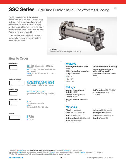
FeaturesInterchangeable with TTP C and HC SeriesAll 316 Stainless Steel construction Multiple Connections ▪ NPT x NPT ▪ SAE x NPT ▪ BSPP x BSPEnd Bonnets removable for servicing Mounting feet included (May be rotated in 90° increments)Special ASME/TEMAC/CRN consult factorySSC Series – Bare Tube Bundle Shell & Tube Water to Oil CoolingMaterialsTubes 316 Stainless steelTubesheets 316L Stainless steel Shell 316L Stainless steelShell Connections 316L Stainless steel Baff l es 316 Stainless steelEnd Bonnets 316 Stainless steel Mounting Brackets Mild steel Gaskets Nitrile rubber/cellulose fiber Nameplate Aluminum foilRatingsMaximum Operating Pressure - Shell Side 300 PSI*Maximum Operating Pressure - Tube Side 150 PSIMaximum Operating Temperature 300°FHeat Removal Up to 350 HP (260 KW)Oil Flow Rates Up to 160 U.S. GPM (350 L/MIN)0223The SSC Series features all stainless steelconstruction. The proven fixed tubesheet design shell and tube heat exchanger offers the cost effectiveness that comes with having a highly standard design, while easily providing for various options to meet specific application requirements. Custom models are also available.TTP’s XSelector sizing program can be used to help optimize the sizing of the cooler for better performance and value.*To register for X Selector please go to /get-in-touch/ and complete the X Selector Inquiry form and submit.Download the X Selector for both Apple and Android formats by searching for X Selector in their App Stores. You must first register for X Selector before using it on mobile devices.** For Salt Water applications a Zinc Anode needs to be plumbed in the water inlet of the cooler to prevent corrosion.Model SeriesModel Size SelectedTube Diameter CodeTubesideBaffle SpacingSSC - NPT Shell side connections x NPT Tube side connectionsSSCS - SAE O-Ring Shell side connections x NPT Tube side connectionsSSCM - BSPP Shell side connections x BSPP Tube side connections614, 624, 814, 824, 836, 1014, 1024, 1036, 1224, 1236, 1248, 1260, 1724, 1736, 1748, 1760, 1772(See Performance Curve Chart on page 3 for sizes)1.3, 1.7, 2,2.5, 3,3.5, 4, 5, 6, 8.4(See Performance Curve Chart on page 3 for options)4 - 1/4”(standard for 600 & 800 Series)6 - 3/8”(standard for 1000, 1200 & 1700 Series)0 - One Pass T - Two Pass F - Four PassHow to OrderOPTIONSFor ASME/TEMAC/CRN ratings consult factorySelection ProcedureSSC-1014-2-6-*33 GPM Max.SSC-1014-5-6-*66 GPM Max.SSC-1724-3.5-6-*105 GPM Max.SSC-1724-8.4-6-*200 GPM Max.Caution: Incorrect installation can cause this product to fail prematurely, causing the shell side and tube side fluids to intermix.Specific applications may have different piping arrangements. Contact factory for assistance.Piping DiagramPerformance Curves are based on 100SSU oil leaving the cooler 40°F higher than the incoming water temperature (40°F approach temperature). Curves are based on a 2:1 oil to water ratio.STEP 1D etermine the Heat Load. This will vary with different systems, but typically coolers are sized to remove 25 to 50% of the input nameplate horsepower. (Example: 100 HP Power Unit x .33 = 33 HP Heat load.)If BTU/HR is known: HP = BTU/HR 2545STEP 2Determine Approach Temperature. Desired oil leaving cooler °F – Water Inlet temp. °F = ActualApproachSTEP 3Determine Curve Horsepower Heat Load. Enter the information from above:HP heat load x 40 x Viscosity = Curve Actual Approach Correction A Horsepower STEP 4 Enter curves at oil flow through cooler and curve horsepower. Any curve above the intersecting point will work.STEP 5Determine Oil Pressure Drop from Curves. Multiply pressure drop from curve by correction factor B found on oil viscosity correction curve.l = 5 PSI n = 10 PSI ▲ = 20 PSIOil TemperatureOil coolers can be selected by using entering or leaving oil tempertures.Typical operating temperature ranges are: Hydraulic Motor Oil 110°F - 130°F Hydrostatic Drive Oil 130°F - 180°F Lube Oil Circuits 110°F - 130°F Automatic Transmission Fluid 200°F - 300°FDesired Reservoir TemperatureReturn Line Cooling: Desired temperature is the oil temperature leaving the cooler. This will be the same temperature that will be found in the reservoir.Off-Line Recirculation Cooling Loop: Desired temperature is the temperature entering the cooler. In this case, the oil temperature change must be determined so that the actual oil leaving temperature can be found. Calculate the oil temperature change (Oil #T) with this formula:Oil #T=(BTUs/HR)/GPM Oil Flow x 210).To calculate the oil leaving temperature from the cooler, use this formula:Oil Leaving Temperature = Oil Entering Temperature - Oil #T.This formula may also be used in any application where the only temperature available is the entering oil temperature.Oil Pressure Drop: Most systems can tolerate a pressure drop through the heat exchanger of 20 to 30 PSI. Excessive pressure drop should be avoided. Care should be taken to limit pressure drop to 5 PSI or less for case drain applications where high back pressure may damage the pump shaft seals.5432.521.51.8.7.6.550607080100150200250300400500ABOil Viscosity - SSUV i s c o s i t y C o r r e c t i o nExample Model No.Maximum Flow RatesOne PassTwo and Four PassCOOLING WATERCOOLING WATERViscosity CorrectionPerformance CurvesOil Flow (GPM)H o r s e p o w e r R e m o v e d i n C o o l erS hipping weights are approximate.For additional sizing information consider using TTP’s X Selector online sizing Program.**To register for X Selector please go to /get-in-touch/ and complete the X Selector Inquiry form and submit.Download the X Selector for both Apple and Android formats by searching for X Selector in their App Stores. You must first register for X Selector before using it on mobile devices.** For Salt Water applications a Zinc Anode needs to be plumbed in the water inlet of the cooler to prevent corrosion.One PassGGHHZ (4 places)(both ends)NOTE: We reserve the right to make reasonable design changes without notice. Consult factory. All dimensions are inches.All models exceptSSC-600SSC-600For 3D models and spec sheets visit the SSC product page on our website.https:///product/ssc-seriesSSC-600SSC-1000SSC-1700SSC-800SSC-1200NOTE: We reserve the right to make reasonable design changes without notice. Consult factory. All dimensions are inches.For 3D models and spec sheets visit the SSC product page on our website.https:///product/ssc-seriesFour PassHHoptionNOTE: We reserve the right to make reasonable design changes without notice. Consult factory. All dimensions are inches.All models exceptSSC-1700SSC-1700For 3D models and spec sheets visit the SSC product page on our website.https:///product/ssc-series。
OLAER ULAC油冷器商品介绍说明书

For industrial use – maximum cooling capacity 400 HP
The ULAC oil cooler with AC motor is optimized for use in the industrial sector. Together with a wide range of accessories, the ULAC cooler is suitable for installation in most applications and environments. Choosing the right cooler requires precise system sizing. The most reliable way to size a cooler is with the aid of our calculation program. This program, together with precise evaluations from our experienced, skilled engineers, gives you the opportunity for more cooling per $ invested.
Flow? Pressure? Pump efficiency?
Measure in your existing
unit
Contact Olaer USA representative.
Theoretical Horse power
losses
Choose the right kind of cooler
Overheating - an expensive problem An under estimated cooling capacity produces a temperature that is too high. The consequences are poor lubricating properties, higher internal leakage, a higher risk of cavitation, damaged components, etc. Overheating leads to a significant drop in efficiency which can be detrimental to our environment.
燃油加热器使用手册说明书
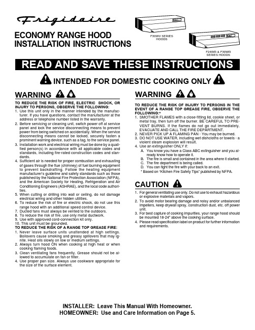
TO REDUCE THE RISK OF FIRE, ELECTRIC SHOCK, OR INJURY TO PERSONS, OBSERVE THE FOLLOWING:e this unit only in the manner intended by the manufac-turer. If you have questions, contact the manufacturer at the address or telephone number listed in the warranty.2.Before servicing or cleaning unit, switch power off at service panel and lock the service disconnecting means to prevent power from being switched on accidentally. When the service disconnecting means cannot be locked, securely fasten a prominent warning device, such as a tag, to the service panel.3.Installation work and electrical wiring must be done by a quali-fied person(s) in accordance with all applicable codes and standards, including fire-rated construction codes and stan-dards.4.Sufficient air is needed for proper combustion and exhausting of gases through the flue (chimney) of fuel burning equipment to prevent backdrafting. Follow the heating equipment manufacturer’s guideline and safety standards such as those published by the National Fire Protection Association (NFPA),and the American Society for Heating, Refrigeration and Air Conditioning Engineers (ASHRAE), and the local code authori-ties.5.When cutting or drilling into wall or ceiling, do not damage electrical wiring and other hidden utilities.6.To reduce the risk of fire or electric shock, do not use this range hood with an additional speed control device.7.Ducted fans must always be vented to the outdoors.8.To reduce the risk of fire, use only metal ductwork.e with approved cord-connection kit only.10. This unit must be grounded.TO REDUCE THE RISK OF A RANGE TOP GREASE FIRE:1.Never leave surface units unattended at high settings.Boilovers cause smoking and greasy spillovers that may ig-nite. Heat oils slowly on low or medium settings.2.Always turn hood ON when cooking at high heat or when cooking flaming foods.3.Clean ventilating fans frequently. Grease should not be al-lowed to accumulate on fan or filter.e proper pan size. Always use cookware appropriate for the size of the surface element.F30WV SERIESHOODSF24WR & F30WR SERIES HOODSECONOMY RANGE HOODINSTALLATION INSTRUCTIONSTO REDUCE THE RISK OF INJURY TO PERSONS IN THE EVENT OF A RANGE TOP GREASE FIRE, OBSERVE THE FOLLOWING:*1.SMOTHER FLAMES with a close-fitting lid, cookie sheet, or metal tray, then turn off the burner. BE CAREFUL TO PRE-VENT BURNS. If the flames do not go out immediately,EVACUATE AND CALL THE FIRE DEPARTMENT.2.NEVER PICK UP A FLAMING PAN - You may be burned.3.DO NOT USE WATER, including wet dishcloths or towels - a violent steam explosion will result.e an extinguisher ONLY if:A.You know you have a Class ABC extinguisher and you al-ready know how to operate it.B.The fire is small and contained in the area where it started.C.The fire department is being called.D.You can fight the fire with your back to an exit.* Based on “Kitchen Fire Safety Tips” published by NFPA.1.For general ventilating use only. Do not use to exhaust hazardous or explosive materials and vapors.2.To avoid motor bearing damage and noisy and/or unbalanced impellers, keep drywall spray, construction dust, etc. off power unit.3.For best capture of cooking impurities, your range hood should be mounted 18-24" above the cooking surface.4.Please read specification label on product for further information and requirements.INSTALLER: Leave This Manual With Homeowner.!INTENDED FOR DOMESTIC COOKING ONLY !6" ROUND DUCTWALL CAPWALL CAP3-1/4" X 10" DUCTROOF CAP3-1/4" X 10" DUCTADJUSTABLE ELBOWWALL CAPTOOLS ANDMATERIALS REQUIRED❏Drill, electric or ratchet drive ❏1/8" Drill bit for drilling pilot holes❏1-1/4" wood bit for drilling electrical wiring access hole ❏One straight blade and one phillips head screwdriver ❏Pliers❏Pencil and ruler and/or tape measure❏Saber saw or keyhole saw for cutting 1" x 2" wood strips tolength and cutting wall or cabinet openings ❏Caulking, metal snips, duct tape, duct (with elbows and tran-sition, if necessary) and roof or wall cap, as required ❏Electrical wiring and supplies of type to comply with localcodes The following materials are required only for installations on recessed bottom kitchen cabinets:❏Two 1" x 2" x 12" (approximate length) wood strips (pur-chase locally)❏Four 1-1/4" long flat head wood screws (purchase locally)PLANNING DUCTWORK INSTALLATION(This section for F30WV hoods only. F30WR and F24WRhoods skip this section and go on to “Prepare the Hood”.)Begin planning ductwork by deciding where the duct will run between the range hood and the outside. For best performance,use the shortest possible duct run and a minimum number of elbows. There are several choices shown - FIGS. A - F below.FIG. A. Ducting directly through the wall (for range hoods mounted on an exterior wall). Shown are two ways to duct through an outside wall. If a wall cap is used directly off the back of the hood, special care must be taken to make sure that the damper in the damper/duct connector on the hood and damper in the wall cap do not interfere with each other when the hood is operating. This could result in either inadequate air delivery or backdrafts. If this condition does exist, remove the hood damper flap. Sometimes when using a wall cap it is easier to duct vertically and then use an elbow as shown in FIG. B.In more complex ducting situations, a 3-1/4" x 10" rec-tangular ducting range hood (F30WV hood) can be converted to a round duct by means of a transition.FIG. C. Ducting straight up through the roof using 3-1/4" x 10" rectangular duct (for single story installations -F30WV hood only).FIG. D. Ducting between the ceiling joists (for multi-story instal-lations) or through the soffit space above the cabinets (where the soffit connects to an outside wall).FIG. E. Straight up through the roof using 6" round duct (for single-story installations).3-1/4" X 10" TO 6"ROUND DUCT TRANSITIONFIG. E6" ROUND DUCTROOF CAP3-1/4" X 10" TO 6"ROUND DUCT TRANSITIONDAMPER/DUCT CONNECTOR (F30WV HOOD ONLY)HINGEPINSDUCTKNOCKOUTS PREPARE THE HOOD1.Unpack hood and check contents. You should receive:1 -Aluminum Filter (F30WV hood only)1 -3-1/4" x 10" Damper/Duct Connector (mountedinside of hood for shipping only) (F30WVhood only)1 - Ductree filter (F24WR and F30WR hoods only)2.Remove wiring box cover. Under cover find:1 -Plastic Bag containing loose mounting hard-ware3.Remove top or rear electrical knockout. (FIG. 2)4.(F30WV hood ONLY) Remove duct knockout. Insert screw-driver under edge of knockout, break tabs, and peel knock-out back with pliers. (FIG. 3)5.(F30WV hood ONLY) Install damper/duct connector overopening made in STEP 4. Use #8B sheet metal screws pro-vided. (FIG. 3)WIRING BOX COVERDUCTFREEFILTER(F24WR &F30WRHOODONLY)ALUMINUMFILTER(F30WVKEYHOLESLOTSPREPARE THEINSTALLATION LOCATIONOmit STEP 1 if hood will be installed under cabinets with flushbottom.1.(For installation on recessed bottom cabinets only) Attach awood filler strip at each side of recessed area under cabi-net. Use two 1" x 2" strips cut to length. If recess is deeperthan 1" use thicker strips. Attach strips with 1-1/4" woodscrews, 3" from each end of strip. See FIG. 4.2.Measure and mark the following (FIGS. 5A & 5B):a.) Electrical wiring opening in wall or cabinet.e 1-1/4" bit to drill opening for electric wiring.4.Cut out duct opening in wall or cabinet with saber saw orkeyhole saw.5.Center hood in installation opening and trace keyhole slotsonto wood filler strips on cabinet bottom.6.Screw four #10 x 7/8 wood screws into exact center of narrowend of traced keyhole slots. Allow 3/8" of screws to project, sothat hood can be fitted into place later.ELECTRICALKNOCKOUTSFIG. 5ACENTER LINEFILLER STRIP**10-15/16" FOR 24" RANGE HOOD, 13-15/16" FOR 30" RANGE HOOD FIG. 6FIG. 7FIG. 8SOFFITFIG. 5BF24WR,F30WR & F30WV1.Run electric wiring through hole drilled in wall or cabinet. Split wir-ing for 6" and install proper connector for type of wire used. (FIG. 9)2.Position hood so that:a.)Wiring is routed through knockout opening (FIG. 10)b.)Large part of keyhole slots fit over hood mounting screws.(FIG. 10)c.)Damper/duct connector slides into ductwork.(F30WV hoods only)3.Adjust hood so that hood front is flush with cabinet frame.4.Tighten hood mounting screws firmly.5.Fasten wiring to hood with proper electrical connector for type of6.Strip 1/2" of insulation from wires. Connect white to white, black to black, and green to prepared hole with green ground screw pro-vided. (FIG. 11)7.Replace wiring box cover and screw. Make sure that all wiring is safely contained inside.8.Install light (75 Watt maximum). For easier installation, squeeze plas-tic lens and remove it from hood. Remember to reinstall lens. (FIG.12)9.Turn on power and check operation of fan and light. Make sure that damper operates freely.KEYHOLE SLOT OUTLINECENTER LINEFILLER STRIPSWALL CAPCABINETROOF CAPDUCTSOFFITCABINETINSTALL THE DUCTWORK(This section for F30WV hoods only. F24WR and F30WR hoods HOOD WIDTHCONNECTORSOCKET LIGHT LENSFAN ASSEMBLYRemove filter. Remove two screws holding motor bracket to range hood, and unplug fan assembly. Be careful not to allow fan assembly to drop when screws are removed. (FIG. 14)CLEANINGClean your hood with a mild detergent suitable for painted sur-faces. DO NOT USE ABRASIVE CLOTH, STEEL WOOL PADS OR SCOURING POWDERS.Fan assembly may be vacuumed. Fan assembly is permanently lubricated, and never needs oiling.HOW TO AVOID A COMMON RANGE-TOP GREASE FIRE •Your range hood provides a protective barrier between the cooking surface and the cabinets.•Keep fan, filters and grease laden surfaces CLEAN ac-cording to instructions.•Always turn hood ON when cooking at high heat to keep the cooking area and the hood cooler.•Use high heat settings only when necessary.•Never leave cooking surface unattended. Boil-over causes smoking and greasy spillovers that may ignite.•Always use adequate-sized utensils.•If preparing flaming foods, such as Cherries Jubilee, always turn hood ON to HIGH to prevent a high heat situation which can cause damage or fire.HOW TO EXTINGUISH A COMMON RANGE-TOP GREASE FIRE•Never pick up a flaming pan. If dropped, flames can spread quickly.•DO NOT USE WATER! A violent steam explosion may result. Wet dishcloths or towels are also dangerous.•Smother flames with a close fitting lid, cookie sheet or metal tray.•Flaming grease can also be extinguished with baking soda or a multi-purpose dry chemical extinguisher.•Turn off surface units - if you can do so without gettingBLACKWIRES GREEN GROUND SCREWGROUND WIRE (BARE ORGREEN WIRE)GROUNDINGBRACKETSTARLOCKNUTWHITE WIRESUSE AND CARESWITCHESThe fan and light are each controlled by a rocker switch. Thelight switch has two positions, “ON” and “OFF”. The fan switchhas three positions - “HIGH”, “LOW” and “OFF”. ( “OFF” is themiddle position.)FILTERSF30WV Hood Only:Remove aluminum filter by turning filter retainer to one side.(FIG. 13) Filter should be washed once a month in a hot deter-gent solution. Aluminum filters are dishwasher safe. When in-stalling filter, make sure that filter slides under retaining tabs onback of fan housing. Turn filter retainer so that arrows on re-tainer point toward front and back of hood.F24WR & F30WR Hoods Only:The F24WR AND F30WR hoods are equipped with a ductfreefilter. Remove filter by turning filter retainer to one side. (FIG. 13)The ductfree filter is not washable, and will last up to twelve monthswith normal use. Replace the filter when colored side becomesnoticeably dirty or discolored.When installing filter, make sure that filter slides under retain-ing tabs on back of fan housing. MAKE SURE THAT COLOREDSIDE OF FILTER IS NEXT TO FAN WHEN FILTER IS IN-STALLED. Turn filter retainer so that arrows on retainer pointtoward front and back of hood.FILTERFILTER RETAINERTABSSCREWSSERVICE PARTSF30WV SERIES 3-1/4" X 10"DUCTED HOODKEY NO.DESCRIPTION1Outlet Box Cover2#8 x 3/8 Sheet Metal Screw* 3Bulb Holder with Wires 4Light Lens5Screw/Nut Kit (Includes 2 - #10-16 x .500screws and 2 - #10-16 sheet metal nuts) 6Fan Blade7#6-32 Locking Nuts* (2 Required) 8Motor Mounting Bracket9Motor Assembly (Includes Key Nos. 6, 7, & 8)10Aluminum Filter 11Filter Retainer12#8B x 1/4 Hex Head Sheet Metal Screws*(2 Required)13Damper Flap 14Damper Bushing 15Damper Assembly(Includes Key Nos. 13, 14 and 21)16Nameplate - Black Nameplate - White172-Speed Motor Switch - Black 2-Speed Motor Switch - White 18Light Switch - Black Light Switch - White19Motor Receptacle with Wires20#10-32 x 1/2 Green Ground Screw*21Damper Bumper**Light Bulb, 75 Watt (not included)*Order service parts by "KEY NO."* Standard Hardware. May be purchased locally.** Not Illustrated.21SERVICE PARTSF30WR & F24WR SERIESNON-DUCTED HOODKEY NO.DESCRIPTION1Outlet Box Cover2#8 x 3/8 Sheet Metal Screw*3Bulb Holder with Wires4Light Lens5Screw/Nut Kit (Includes 2 - #10-16 x .500screws and 2 - #10-16 sheet metal nuts)6Fan Blade7#6-32 Locking Nuts* (2 Required)8Motor Mounting Bracket9Motor Assembly(Includes Key Nos. 6, 7, & 8)10Ductfree Filter11Filter Retainer12Nameplate - Black17 Nameplate - WhiteNameplate - Bisque132-Speed Motor Switch - Black2-Speed Motor Switch - White2-Speed Motor Switch - Bisque14Light Switch - BlackLight Switch - WhiteLight Switch - Bisque15Motor Receptacle with Wires16#10-32 x 1/2 Green Ground Screw*17Grommet**Light Bulb, 75 Watt (not included)*Order service parts by "KEY NO."* Standard Hardware. May be purchased locally.** Not Illustrated.This warranty does not cover the following:1.Products with original serial numbers that have been removed, altered or cannot be readily determined.2. Product that has been transferred from its original owner to another party or removed outside the USA orCanada.3. Rust on the interior or exterior of the unit.4. Products purchased "as-is" are not covered by this warranty.5. Food loss due to any refrigerator or freezer failures.6.Products used in a commercial setting.7. Service calls which do not involve malfunction or defects in materials or workmanship, or for appliancesnot in ordinary household use or used other than in accordance with the provided instructions.8. Service calls to correct the installation of your appliance or to instruct you how to use your appliance.9. Expenses for making the appliance accessible for servicing, such as removal of trim, cupboards, shelves, etc.,which are not a part of the appliance when it is shipped from the factory. 10.Service calls to repair or replace appliance light bulbs, air filters, water filters, other consumables, or knobs,handles, or other cosmetic parts.11.Surcharges including, but not limited to, any after hour, weekend, or holiday service calls, tolls, ferry tripcharges, or mileage expense for service calls to remote areas, including the state of Alaska.12. Damages to the finish of appliance or home incurred during installation, including but not limited to floors,cabinets, walls, etc.13.Damages caused by: services performed by unauthorized service companies; use of parts other than genuineElectrolux parts or parts obtained from persons other than authorized service companies; or external causes such as abuse, misuse, inadequate power supply, accidents, fires, or acts of God.DISCLAIMER OF IMPLIED WARRANTIES; LIMITATION OF REMEDIESCUSTOMER'S SOLE AND EXCLUSIVE REMEDY UNDER THIS LIMITED WARRANTY SHALL BE PRODUCT REPAIR OR REPLACEMENT AS PROVIDED HEREIN. CLAIMS BASED ON IMPLIED WARRANTIES, INCLUDING WARRANTIES OF MERCHANTABILITY OR FITNESS FOR A PARTICULAR PURPOSE, ARE LIMITED TO ONE YEAR OR THE SHORTEST PERIOD ALLOWED BY LAW, BUT NOT LESS THAN ONE YEAR. ELECTROLUX SHALL NOT BE LIABLE FOR CONSEQUENTIAL OR INCIDENTAL DAMAGES SUCH AS PROPERTY DAMAGE AND INCIDENTAL EXPENSES RESULTING FROM ANY BREACH OF THIS WRITTEN LIMITED WARRANTY OR ANY IMPLIED WARRANTY . SOME STATES AND PROVINCES DO NOT ALLOW THE EXCLUSION OR LIMITATION OF INCIDENTAL OR CONSEQUENTIAL DAMAGES, OR LIMITATIONS ON THE DURATION OF IMPLIED WARRANTIES, SO THESE LIMITATIONS OR EXCLUSIONS MAY NOT APPLY TO YOU. THIS WRITTEN WARRANTY GIVES YOU SPECIFIC LEGAL RIGHTS. YOU MAY ALSO HAVE OTHER RIGHTS THAT VARY FROM STATE TO STATE.Keep your receipt, delivery slip, or some other appropriate payment record to establish the warranty period should service be required. If service is performed, it is in your best interest to obtain and keep all receipts.Service under this warranty must be obtained by contacting Electrolux at the addresses or phone numbers below.Your appliance is covered by a one year limited warranty . For one year from your original date of purchase,Electrolux will pay all costs for repairing or replacing any parts of this appliance that prove to be defective in materials or workmanship when such appliance is installed, used, and maintained in accordance with the provided instructions.This warranty only applies in the USA and Canada. In the USA, your appliance is warranted by Electrolux Major Appliances North America, a division of Electrolux Home Products, Inc. In Canada, your appliance is warranted by Electrolux Canada Corp. Electrolux authorizes no person to change or add to any obligations under this warranty. Obligations for service and parts under this warranty must be performed by Electrolux or an authorized service company. Product features or specifications as described or illustrated are subject to change without notice.USA1.800.944.9044Electrolux Major Appliances North America P .O. Box 212378 Augusta, GA 30907Canada1.800.668.4606Electrolux Canada Corp.5855 Terry Fox WayMississauga, Ontario, CanadaL5V 3E4ExclusionsIf You Need Service。
- 1、下载文档前请自行甄别文档内容的完整性,平台不提供额外的编辑、内容补充、找答案等附加服务。
- 2、"仅部分预览"的文档,不可在线预览部分如存在完整性等问题,可反馈申请退款(可完整预览的文档不适用该条件!)。
- 3、如文档侵犯您的权益,请联系客服反馈,我们会尽快为您处理(人工客服工作时间:9:00-18:30)。
燃油不清洁引起典型故障
燃油不清洁,造成燃油水寒宝泵芯部件进口端滤网被堵塞, 总成出 口流量偏低,发动机启动比较困难。 原因: 1. 燃油滤清器超过了使用期限.
2. 发动机长时间不工作,管道里的残油粘结成固状膜. 3. 颗粒杂物进入了燃油.
插头电线损坏引起典型故障
插头电线损坏,造成燃油水寒宝断路,造成燃油水寒宝不能工作,发动机 启动困难. 原因: 导线损坏,产生断路.
谢 谢!
温州华科工业发展有限公司 2011年2月
燃油水寒宝技术背景及工作情
况
技术背景: 为了解决柴油发动机启动困
难和柴油发动机普遍存在低温环境下 和长时间停放的车辆及维修发动机燃 油系统后,使低压燃油管路内进入空 气无法排空,华科经过数年精心研制 和借鉴国外同行的开发经验,终于研 制出了数款物美价廉的一体化电动输 油泵及滤清器总成产品。 工作情况:
燃油水寒宝安装示意图
燃油水寒宝线束的安装 第一步:分别连接整车24V正极、负极以及点火钥匙ON档。24V正极、负极连接在 驾驶室内电器保险盒内正负极接线柱,如下图红色框图所示。
第二步:根据图一的红色连接线束示意将线束的电源线与水寒宝的接线柱连接。 第三步:线束连接完毕后,挑选平整干净区域将燃油水寒宝控制盒背面魔术贴粘贴 牢靠。 第四步:连接完成后,对线束进行适当捆扎及紧固并拧钥匙开关至ON档,检查燃油 水寒宝的工作情况。 注意:燃油水寒宝与车身连接,不需要额外搭铁线。
初步判断燃油水寒宝是否产生故障
检查燃油水寒宝总成是否出现断路和短路: 一.将万用表打到”检测通路”档,将正,负探针分别接触泵的正,负极,若听 到”di”的声音则排除了泵断路故障. 二.将万用表打到”200Ω”档,将正,负探针分别接触泵的正,负极,若电阻值不 是无限接近”0”则排除了短路故障. 如果控制器出现断路和短路,则只需更换控制器.如果水寒宝泵芯出现断路和 短路,则需要更换燃油水寒宝总成。
燃油水寒宝失效最常见的原 因
■管道联接不密封 ■燃油不清洁 ■插头电线损坏
管道联接不密封引起典型故障
管道联结不密封,造成电动输油泵吸油困难, 总成出口流量偏低, 发动机启动比较困难. 原因: 1. 燃油泵总成与燃油管道联结不密封.
2. 四处螺栓因长期震动有松动. 3. 螺栓密封垫圈损坏. 4. 输油管不密封.
电动泵工作时, 电动泵在吸油, 燃油不经过单向阀
电动泵不工作时, 燃油不经过电动泵, 燃油只需经过单向阀
燃油水寒宝安装示意图
燃油水寒宝的安装 燃油水寒宝是发动机的第一级燃油滤清器,安装在车架上。用两个M12的螺栓将水 寒宝安装在车架上并拧紧,将线束的DJ431-4C端子和水寒宝的电源输入接线柱用自 带的M4螺钉拧紧,连接方式如下图所示:
发动机点火开关一打开,电
动式输油泵就通电工作,工作时间为
10分钟。10分钟由继电器来控制,时
间一到就自动断开,然后齿轮泵就直
接从油箱里吸油,燃油经过水寒宝铝 底座的单向阀(不再经过泵),给发 动机燃烧室供油。
燃油水寒宝
零件号:6126流向
入口
入口
产品安装检查
1.检查发动机燃油滤清器是否在使用期限内,若超限则过滤效果差,易引起燃 油泵流量偏小,需更换新滤清器.
2.检查密封垫圈是否有腐蚀,变形现象,如果有则需更换垫圈,不得使用密封胶. 3.燃油应使用发动机厂家推荐牌号.
日常保养
1.只能使用发动机厂家推荐的柴油. 2.只能使用发动机厂家推荐的燃油滤清器和连接管. 3.不得在进油口密封处使用密封胶. 4.定期更换燃油滤清器. 5.定期检查输油管连接螺栓是否有松动.