WMR6 说明样本
三星AMOLED驱动芯片中文版说明书
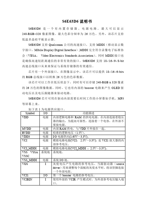
如表 2 所示为系统接口。 Symbol I/O 功能描述 S_PB I 选择 CPU 接口模式,低电平时为并行接口,高电平时为串行 接口。 MDDI_E I 选择 MDDI 接口,低电平时 MDDI 接口不可用,高电平时 N MDDI 接口可用。 ID_MIB I 选择 CPU 种类, 低电平为 intel 80 系列 CPU, 高电平为 motorola 68 系列 CPU,如果 S_PB 是高电平,该端口为 ID 设置端口。 CSB I 片选信号,低电平芯片可用,高电平芯片不可用。 RS I 寄存器选择管脚。 低电平时,指令/状态,高电平时为指令参数/RAM 数据。 不用时需与 VDD3 接在一起。 RW_WR I 管脚作用 CPU 种类 管脚说明 B/SCL RW 68 系列 读写选择,低电平写,高电平读。 WRB 80 系列 写选通作用,在上升沿捕获数据。 SCL 串行接口 时钟同步信号。 E_RDB I 管脚作用 CPU 种类 管脚说明 E 68 系列 读写操作使能端。 RDB 80 系列 读选通作用,低电平时读出数据。 选择串行模式时,将此端口接在 VDD3 上。 SDI I 串行接口的数据输入接口,在 SCL 上升沿捕捉到输入数据,
表 2 系统接口
表3为 Symbol MDP MDN MSP MSN GPIO[9:0] (DB[17:8]) S_CSB(DB [7])
MDDI 管脚作用。 I/O 功能描述 I/O MDDI 数据输入/输出正端,如果 MDDI 不用,该端口悬空。 I/O MDDI 数据输入/输出负端,如果 MDDI 不用,该端口悬空。 I MDDI 数据选通输入正端,如果 MDDI 不用,该端口悬空。 I MDDI 数据选通输入负端,如果 MDDI 不用,该端口悬空。 I/O 总体输入输出,如果在 MDDI 中没有用 GPIO 的话,这些管 脚应该置地。 O 子屏幕驱动 IC 片选信号。 低电平时说明子屏幕驱动 IC 可用,高电平时说明子屏幕驱动
R550 R600 R650 R750 使用说明书

Imprint:Instruction Manual R550 / R600 / R650 / R750© ROTHENBERGER Werkzeuge GmbH, 2003We reserve the right to revise product specifications at any time without notice. Editorial/Typeset/DTP: ROTHENBERGER Werkzeuge GmbH • D-65779 Kelkheim Edition 09 / 2003Printed in the F.R. of GermanyPlease read the Instruction Manual carefully first! • Don't throw it away! If damages are caused by operating errors or misuse the warranty expires!Contents PageComments 121. Safety1.1 Use in accordance with the regulations 121.2 Applied safety symbols and their meaning 121.3 Indication to the safety of man and machine 122. Technical Data 143. Function of the Unit 1414Description3.1Design/summery14Equipment3.1.1description14Functional3.1.2Operation153.23.3 Removal of pipe blockages 163.4 Retrieval of the spirals from the pipe 16Toolchanging 163.53.6 Working using 8 mm or 10 mm spirals 1717Shut-down3.74. Troubleshooting 17Repair 185. Serviceand5.1Service 1818Repair5.2Maintenance,Recondition,5.2.1 Changing of the clamp-mounting system 186. Disposal 197. CE-Statement of Conformity 198. Warranty s. appendix 11. Safety Comments1.1Use in accordance with the regulationsThe drain cleaning machines are only to be used for pipe cleaning of the following pipe-diameters:R550 20-100mm / R600-650 20-150mm / R750 20-200mmThe drain cleaning machines may not be operated under load longer than 15 minutes.1.2Applied safety symbols and their meaningFailure to comply with these safety marks (WARNING) means danger to life and health ofindividuals.Failure to comply with these safety marks (CAUTION) means a possibly dangerous situation whichmay result in injuries or damage to property.This symbol (NOTE) points to important advice for the proper handling of the machine. Failure tocomply with these notes may cause malfunction of themachine or interference to the environment.1.3 Indication to the safety of man and machineKeep your working area in an orderly state. Disorder can cause accidents!Bear ambient factors of influences in mind. Do not expose electrical power tools to rain.Do not use electrical power tools in damp or wet environments. Ensure good lighting. Do not useelectrical power tools in the proximity of combustible liquids or gasesProtect yourself from electric shock. Avoid bodily contact with earthed parts, e.g. pipes,radiators, cookers, refrigerators!Keep children away. Do not allow other persons to touch the tool or flex. Keep other personsaway from your working area.Store your tools safely. Unused tools should be stored in a dry and locked room and in such away that they are not accessible to children.Do not overload your tool. You will work better and more safely if you stay within thespecified capacity range.Use the proper tool. Do not use tools or adapter devices which are too weak for heavy work.Do not use tools for purposes and work for which they were not intended, e.g. do not usehandheld circular saws to cut trees or branches.Wear suitable work clothing. Do not wear wide clothing or jewellery, both of which can becaught by moving parts. When working outdoors, rubber gloves and anti-slip shoes are advisable.If your hair is long, wear a hairnet.Wear protective goggles. Use an oxygen mask for work where a dusty atmosphere is likely tobe generated.Do not misuse the flex. Do not carry the tool by the flex and do not use the flex to pull the plug out of the socket outlet. Protect the flex from heat, oil and sharp edges.Secure the work piece. Use clamping mechanisms or a vise in order to secure the work piece. In that way, the work piece is held more securely than when held by your hand and allows you instead to operate the machine using both hands.Do not overextend your standing area. Avoid abnormal postures. Ensure that you are standing safely and have proper balance at all times.Take care of your tools meticulously. Keep your tools sharp and clean to enable you to workwell and safely. Adhere to the maintenance instructions and the instructions for tool changing. Check the plug and the flex regularly and, if they are damaged, have them upgraded by an approved professional. Check the extension cable regularly and replace it if damaged. Keep the handgrips dry and free from oil and grease.Pull out the mains plug when not using the tool, before performing maintenance work and when changing a part of the tool, such as e.g. saw blade, drill and machine tools of all kinds.Do not leave a tool wrench inserted. Before switching on the power, check that the wrenches and setting tools are removed.Avoid starting the tool unintentionally. Do not carry tools which are connected to thepower mains while holding your finger on the switch. When plugging the tool into the power mains, make sure that the switch is off.Extension cables outdoors. When working outdoors, only use extension cables which areapproved for this purpose and correspondingly labelledBe at all times attentive. Monitor your work. Proceed rationally. Do not use the tool if you are not able to concentrateCheck your appliance for damage. Before using the tool any further, check carefully that the protective mechanisms and any slightly damaged parts are functioning perfectly and in line with the regulations and with their intended purpose. Check that the moving parts are functioning properly, that they are not stuck and that no parts are damaged. All parts must be mounted properly and all conditions fulfilled in order to ensure the sound operation of the appliance. Where not otherwise stated in the operating manuals, damaged protective devices and parts should be properly repaired by a customer service workshop or replaced by same. Damaged switches must be replaced by a customer service workshop. Do not use tools on which the power switch cannot be switched on and off .Caution. For your own safety, only use accessories and auxiliary devices which are specified foruse in the operating manual or recommended or specified by the tool manufacturer. The use of tools or accessories other than those recommended in the operating manual or in the catalogue can entail a danger of personal injury to you.Have your electrical power tools repaired by a skilled electrical specialist. ROTHENBERGER electrical power tools are in accordance with the relevant safety regulations. Repairs are only permitted to be performed by a skilled electrical specialist. Otherwise, accidents can happen to the user.Data2. TechnicalR550 R600 Saniclean R650 Powerclean R750 Motor rating 250 Watt 400 Watt 800 Watt 900 Watt07.2655 07.2665 07.2670 07.2910Voltage 230 V; 50 Hz 230 V; 50 Hz 220-240 V; 50 Hz 220-240 V; 50 Hz07.291107.2863 07.2869110/115V; 50Hz 110/115V; 50Hz 110/115V; 50Hz Operating speed 575 U/min 460 U/min 620 U/min 460 U/minWeight 15 kg 20,9 kg 22,8 kg 29,5 kgSpirals Ø16 Ø16; Ø22 Ø16; Ø22 Ø16; Ø22; Ø32(Ø8;Ø 10with (Ø8;Ø 10with (Ø8;Ø 10with (Ø8;Ø 10withaccessories) accessories) accessories) accessories) max. working length 40m 60m 65m 80mdiameterPipeRange Ø20-Ø100mm Ø20-Ø150mm Ø20-Ø150mm Ø20-Ø200mmNoise level 75 dB (A) 75 dB (A) 80 dB (A) 80 dB (A)I I I IclassProtectionUnitthe3. Functionof3.1 Design/Description3.1.1 Equipment summeryEquipment summary/Controls (>see fold-out page)Abb.1 : A = Hand lever B = Main switch C = SpiralD = ToolE = Holder for spiralF = Power cableAbb.2 : (Access.) G = Spirals H = Guide hose I = Spray for spiralK = safety gloves L = Tools3.1.2 FunctionaldescriptionIn the model R550 / R600 / R650 / R750, you have purchased a highly efficient, portable and easy-to-usedrain-cleaning machine.The machine functions on the "Sectional Cable" principle, i.e., only as many spirals as are necessary arecoupled together.This makes it possible to design the machine with a speed of rotation which permits efficient pipe cleaning witha diverse range of tools.The machine is electrically driven. The power of the motor is transmitted to the spirals via the clamp-mountingsystem by exerting pressure on the hand-lever.If the hand-lever is an inoperative position, you can push up the lockpin and the hand-lever can be used as antransport handle. If you push down the hand-lever , the locking is released.By model R650 Powerclean , the hand-lever can be installed either as a centre-mounted or as a side-mountedlever.By model R750 the Handle can also be swung backwards through 180° and locked whenwheeling the machine.Lockpin of hand leverR 650 Powerclean R 750Forward movement towards the pipe blockage is sensitively generated via a so-called working arc on the spiralsbetween the machine and the pipe to be cleaned.The machine is designed for the following diameter spirals:R550 ∅ 16mmR600/650 ∅ 16, 22mmR750 ∅ 16, 22, 32mmAccessories make it possible to use 8 mm and 10 mm diameter spirals for tight bends in sanitary systems.Maximum working range is around the following spiral length :R55040mspirallengthR60060mspirallengthR650/75080mspirallength3.2 OperationWarning! The operation of the drain-cleaning machines shall only be carried outobserving all notes concerning the safety of man and machine.The machine should be positioned at a distance of 50 to 80 cm from the entry to the pipe to be cleaned; themains plug should be connected to the correct electrical supply.If 16 mm or 22 mm diameter spirals are to be used, the fixing element of the guide hose should be insertedinto the hole on the rear of the machine and correctly locked using the attached fixing element and catcher.The guide hose serves as a vibration-absorbing guide element for the spirals, as a dirt trap, and as a safetyelement for the operating staff.The spiral should now be inserted into the machine and coupled at the front by means of a suitable tool. Thetool should be selected to accord with the suspected type of fouling.Important! Put on safety gloves before any other actions are performed!CatcherThe spiral should now be inserted approx. 500 mm into the pipe to be cleaned and the drain-cleaning machinestarted in forward mode. The spirals should be moved manually toward the point of fouling. Once a slightresistance is felt (blockage), the spirals should again be withdrawn from the machine until an arc relative to thepipe occurs. This so-called working arc should be maintained with one hand (wear gloves!) while the hand-lever is pressed down using the other hand; the spirals will now start to rotate.3.3Removal of pipe blockagesThe working arc produced should be pressed downward by the operator, generating a pressure towards theblockage with the drain-cleaning machine remaining in its position. The working pressure resulting from thespirals intrinsic tension and manual pressure acts against the blockage in the pipe.Once the pre-tensioned working arc has penetrated into the pipe, the hand-lever should be released and thespirals again withdrawn from the machine in order to create a new working arc. This cycle of creation of aworking arc and pushing of the rotating spirals towards the blockage should be repeated until the blockagehas been eliminated.Practical experience indicates that the pipe should be finely "after-cleaned" using a chain flail once theblockage has been dislodged.Note:If a tool has become jammed in the pipe, the machine should be set to reverse and the spirals disengaged fromthe blockage by means of backward and forward movements. The machine should then be reset to forwardand the spirals moved up to the blockage again. The procedure for removal of the blockage should then becontinued as described above3.4 Retrieval of the spirals from the pipeUse one hand to draw the rotating spirals out of the pipe until a slight arc is formed. The hand-lever should bereleased and the motionless spirals then pushed back into the machine. The hand-lever should then be used toclamp and rotate the spirals again. As already described, the spirals should then be drawn further out of thepipe. Once a length of spiral has been returned to the guide tube, it should be uncoupled and drawn out of theguide hose. These sequences should be repeated until all the sections of spiral have been removed from thepipe.3.5 ToolchangingThe most efficient tool for the particular type of blockage should be selected.Tool-changing is performed as follows:the tool attachment key supplied with the machine should beinserted into the side boring of the coupling on the spiralsthe locking bolt of the 2nd half-coupling should be liftedthe coupling should be removed to the side out of the milled recessThe tool selected should be mounted from the side on the couplingworking arc3.6 Working using 8 mm or 10 mm spirals8 mm or 10 mm spirals should be used for narrow pipes and pipe bends. An adapter magazine available as an accessory is needed for this purpose; this contains an 8 mm or 10 mm spirals in a drum (for R750 clamp clips are needed).The adapter magazine should be installed in place of the guide tube.For R750, push the suit clamp clip over the spiral into the boring until the stop face.Work then continues in the same way as with a standard spiral.An adjustable brake is provided on the machine to prevent co-rotation of the adapter magazine. The braking action is achieved by lifting the hand-lever to its extreme end position. If there is no longer an adequatebraking action, the setscrew on the adapter should be slackened and the distance between the casting and the clamp corrected. The setscrew should then be re-tightened.3.7 Shut-down After use of the machine, the rotary switch should be returned to its "0" position and the mains plugdisconnected from the mains. The spirals should be recovered from the pipe as described in Section 3.4. and removed from the machine. The guide hose or the adapter magazine should then be detached from the machine.4. TroubleshootingTroublepossible cause Remedy Machine does not work - no power - check the power supply system - defect of main switch - Contact your service agent - defect of motor - Contact your service agent No rotation of spiral - abrasion of clamp clips - remove clamp clips by using the hand-lever - abrasion of cogged belt - remove cogged belt Adapter with setscrew Adapter magazine incl. spiraleClamp clip for R7505 Service and Repair5.1 ServiceThe machine must be carefully handled and must be cleaned at regular intervals. The spirals and tools must be cleaned and protected after every use. We recommend our special "ROWONAL" care product for this purpose. The machine has one lubricating point on the top exterior and internally for lubrication of the needle bearings. The outer lubricating point must be greased using a universal grease after every five hours of operation. The bearings inside the machine can be reached only by dismantling the right-hand side cover. Lubrication here is recommendable at intervals of one hundred hours of operation.5.2 Maintenance, Recondition, RepairImportant!All maintenance, recondition and repair work shall only be carried out by an introduced professional repairing person.The Rothenberger service locations or else the manufacturer with his repair department are available to help you. Needless to say, we will also send you spare parts at short notice. Please contact please your retailer or the manufacturer.Order your accessories and spare parts from your specialist retailer or using our after-sales hotline:Tel. +49 6195 99 52 14 Fax: +49 6195 99 52 155.2.1 Changing of the clamp-mounting systemWarning! Before changing the clamp-mounting system pull out the power cable of the plug connection!1. Dismantle the cover on the right-hand sideGrease nipple outside Needle bearing Grease nipple is being oppositeplug2. Remove the plug and slacken the locking nut.3. Turn the adjusting screw backwards until the clamp-mounting springs are detensioned and remove theclamp-mounting system.4. Insert the new clamp-mounting system and turn the adjusting screw until the correct functioning position forbraking of the adapter magazine has been reached5. Tighten the locking nut and re-install the plugModel R750 :1.Dismantle the cover on the right-hand side2. Remove the clutch jaws and replace with new oneClutch jaws6. DisposalComponents of the unit are recyclable material and should be put to recycling. For this purpose registered andcertified recycling companies are available. For an environmental-friendly disposal of the non-recyclable parts(e.g. electronic waste)please contact your local waste disposal authority.7. CE-Statement of ConformityWe hereby declare on our sole responsibility that this product is in accordance with the provisions of theDirective 98/37EWG; 73/23EWG; 89/336EWG.For additional information, please contact us at the following postal address or contact one of the subsidiarycompanies specified.Rothenberger Werkzeuge GmbHIndustriestrasse7KelkheimD-65779Germany。
TVR6000中文手册

步驟一、D/A1. D/A2 輸出電壓調整:........................................................36 步驟二、AD/DA 之輸入電壓調整.............................................................37 IF 校正 .................................................................................................................38 IF 電流源校正共分為四個步驟 : ..............................................................38 比對 IF 板 OP 放大器回路電壓是否正常 .................................................38 IF 電流檔位 2,RANGE 0.6A-25A 檔位校正 ...........................................39 IF 電流檔位 1,RANGE 0.01A ~0.5A 檔位校正.......................................40 VR Source 校正....................................................................................................41 基本功能檢查.............................................................................................. 41 效驗方式...................................................................................................... 42 VBR 校正............................................................................................................43 IR 校正................................................................................................................44 第七章、 光遮斷器與啟動訊號..........................................................................45 SOT 負源觸發 .....................................................................................................47 SOT 正源觸發: .................................................................................................48 第八章、 後面板說明..........................................................................................49 第九章、 測試機內視圖......................................................................................51
TWR-K60F120M快速上手指南说明书

TWR-K60F120M TWR-K60F120M-KITTWR-K60F120M Quick Start Guide High-Performance MCUs withTWR-K60F120M Freescale Tower System Development Board PlatformThe TWR-K60F120M board is part of the Freescale Tower System, a modular development board platform that enables rapid prototyping and tool re-use through reconfigurable hardware. The TWR-K60F120M can be used with a broad selection of Tower System peripheral boards.Get to Know the TWR-K60F120M BoardPrimary General-Purpose Tower Plug-In MMA8451 Power/OSJTAGMini-B USB ConnectorFigure 1: Front side of TWR-K60F120M board (TWRPI devices not shown)Figure 2: Back side of TWR-K60F120M boardVBAT (RTC) MC9S08JM60OSJTAGStep-by-Step Installation Instructions• MK60FN1M0VLQ12 MCU (120 MHz ARM® Cortex®-M4 core, floating point unit, 1 MB flash, Ethernet, USB OTG,tamper detection, encryption, NANDflash controller, 144 LQFP)• M C9S08JM60 open source JTAG (OSJTAG) circuit• M icron MT29F2G16ABAEAWP 2 Gb NAND flash• F our user-controlled status LEDs• F our capacitive touchpads and two mechanical pushbuttons• G eneral-purpose TWRPI socket (Tower plug-in module)• T WRPI-TOUCH-STR socket (touch-sensing Tower plug-in)1Install theSoftware and ToolsInstall the P&E Micro Kinetis Tower Toolkit.The Toolkit includes the OSJTAG and USB-to-serial drivers. These can be found onthe DVD under Software.2Configure theHardwareInstall the included battery into the VBAT(RTC) battery holder. Then, connect oneend of the USB cable to the PC and theother end to the power/OSJTAG mini-Bconnector on the TWR-K60F120M board.Allow the PC to automatically configure theUSB drivers if needed.3Tilt theBoardTilt the board side to side to see the LEDson E1–E4 light up as it is tilted. While theboard is held flat, touch the pads onE1–E4 to toggle the LEDs.4Play theMemory GamePress SW2 to play a memory recall gameusing the touch pads E1–E4. A sequencewill light up, then press the touch pads inthe order flashed. If an incorrect sequenceis touched or too much time has elapsed,the LEDs will blink rapidly and the gamewill reset.Press SW1 to return to the accelerometerdemo.5Download the TWR-K60F120M User Manualand Demonstration LabsGo to /TWR-K60F120Mand download the TWR-K60F120M usermanual and demonstration labs.6Download the FreescaleCodeWarrior IDE andMQX™ RTOSDownload the Freescale CodeWarrior IDEand MQX RTOS by clicking on the relevantlinks on the Software tab of the Tower KitDVD.TWR-K60F120M FeaturesTWR-K60F120M Jumper OptionsThe following is a list of all jumper options. The default installed jumper settings areshown in shaded boxes.*NOTE: This option must be selected whenever a Tower System module card that provides a clock on primary elevator pin B24 is connected to the CPU module.Visit /TWR-K60F120M,/K60 or /Kinetis for information on the TWR-K60F120M module, including:• TWR-K60F120M user guide• T WR-K60F120M schematics• T ower System fact sheetSupportVisit /support for a list of phone numbers within your region.WarrantyVisit /warranty for completewarranty information.For more information, visit /Tower Join the online T ower community at Freescale, the Freescale logo, CodeWarrior, the Energy Efficient Solutions logo, Kinetis and Xtrinsic are trademarks of Freescale Semiconductor, Inc., Reg. U.S. Pat. & Tm. Off. Tower is a trademark of Freescale Semiconductor, Inc. All other product or service names are the property of their respective owners. ARM and Cortex are registered trademarks of ARM Limited (or its subsidiaries) in the EU and/or elsewhere. All rights reserved.© 2012, 2014 Freescale Semiconductor, Inc.Doc Number: TWRK60F120MQSG REV 2 Agile Number: 926-78653 REV DTWR-K60F120M TWR-K60F120M-KIT。
Wamore 产品说明书

从货运飞机上将高达 42,000 磅的有效载荷通过降落伞投向地面是一个非常冒险的提议。
为了确保空投的有效载荷完整无损地命中目标,需要像 Wamore, Inc. 这样的公司提供的专业技术。
这家位于亚利桑那州的公司所生产的产品被用来给主动作战地区的美军提供支援。
其产品范围包括从空中导航设备 (AGU) 和惯性卷筒到降落伞释放控制系统和软着陆气囊。
据 CAD 专家 Mark Gerhart 介绍,虽然多年使用 SolidWorks ®设计、仿真和产品数据管理 (PDM) 解决方案的经历已经让 Wamore 获益匪浅,但是为其机器人控制的自主空投系统提供装配说明书仍然存在着许多难题。
“以前我们创建装配说明书就像是打一场艰难的战役。
”Gerhart 回忆道,“基本上,我们必须先在装配过程中给设备拍摄照片,然后将照片放入到文档中,同时附注文字说明,解释如何在车间中装配使用该产品。
”虽然这种制作装配说明书的方法对 Wamore 有效,但是该方法效率低下,存在许多的难题,而且与理想相差甚远。
“有几个问题亟待解决。
”Gerhart 解释道,“首先,如果要对我们的产品进行任何设计上的改动,必须彻底重做说明书,而且需要另外拍摄照片。
我们还必须等到特定的生产阶段才能拍摄照片,这造成了时间上的延误。
最后,要么照片总是不够清楚和精细,要么我们的制作人员看不懂书面说明,给设计师和工程师带来了一连串的问题。
”为了解决这些问题,该公司开始寻找能够将装配说明书的创建与实际的实体模型关联起来的解决方案。
“我花了很长时间去寻找这种解决方案。
”Gerhart 强调道,“当我听说 3DVIA Composer™ 软件时,我对自己说,‘为了能够以更高的效率为我们的产品制作出装配说明文档,我们必须拥有该软件。
’”案例研究WAMORE, INC.利用 3DVIA Composer将空投装置说明书提高到一个新的水平难题:以更高的效率创建更加简明易懂的空投系统装配说明书,而且毋须等到相应的生产阶段再去采集照片图像。
新建MGW(R6版本)数据总结-武伟龙

新建MGW(R6版本)数据总结-武伟龙新建MGW(R6版本)总结数据部分:A口部分:N_0510_DS0BUNDLE:定义传输时隙,定义到ODF(光纤分布框)的,为光纤直拉,如到BSC局的(除了HSL 的),每根E1单独定义,Vc12Ttp为乱序值,乱序是光纤直连(1、22、43、4的顺序~~~~),31:31个时隙全部使用,1-31:全部走话务。
//CREATEManagedElement=1,Equipment=1,Subrack=MSE1,Slot=8,Pl ugInUnit=1,ExchangeTerminal= 1,Os155SpiTtp=MSE1-8-1,Vc4Ttp=1,Vc12Ttp=22,E1Ttp=1,Ds0Bundle=MSE1-8-1-02/01_31 ECHO "======>MSE1-8-1-02/01_31"CREATE(parent"ManagedElement=1,Equipment=1,Subrack=MSE1,Slot=8,P lugInUnit=1,ExchangeTerminal =1,Os155SpiTtp=MSE1-8-1,Vc4Ttp=1,Vc12Ttp=22,E1Ttp=1"identity "MSE1-8-1-02/01_31"moType Ds0Bundleexception nonenrOfAttributes 3userLabel String "TOLBSC5_2 MSE1-8-1-02/01_31"listOfTimeSlots Array Integer 31 1 2 3 4 5 6 7 8 9 10 11 12 13 14 15 16 17 18 19 20 21 22 23 24 25 26 27 28 29 30 31tdmMode Boolean true)N_1420_TDM_TERM_GROUP:话务终端组,定义的是ds0bundle中的所有的话务的时隙其中的partial fill参数,指出在atm传输中的字节数,默认值是40。
摩克斯W6000系列无线计算机说明书
W6000 SeriesOverviewThe W6000 series computers are embedded Linux computersfeaturing 2 software selectable RS-232/422/485 ports, 1 Ethernet port, and LTE/US, HSPA, GPRS/GSM, and GPS for complex communication solutions. All W6000 computers come with a microSD socket for external storage expansion. The W6000 computers’ Linux OS runs on the 32-bit ARM Cortex-A8 processor, which provides a powerful and reliable platform for harsh, industrial environments.The W6000 is built around a low-power Cortex-A8 RISC processorand Debain ARM Linux OS that has been optimized for use in energy monitoring systems, but is widely applicable to a variety of industrial solutions. With powerful computing and multiple communicationoptions, this tiny embedded computer is a reliable and secure gateway for data acquisition and processing at field sites as well as a useful communication platform to replace individual computers and routers for many other large-scale deployments.Appearance(RS-232/422/485, terminal block)Hardware SpecificationsComputerCPU: ARMv7 Cortex-A8 300 MHz (600 MHz, 1 GHz by project) USB: USB 2.0 hosts x 1, type A connectorDRAM: DDR3 SDRAM: 512 MBOS (pre-installed): Debian ARM 8 (Kernel 4.0)StorageStorage Expansion: MicroSD socket for storage expansion Ethernet InterfaceLAN: Auto-sensing 10/100 Mbps ports (RJ45) x 1Magnetic Isolation Protection: 1.5 kV, built-inSerial InterfaceSerial Standards: RS-232/422/485 ports, software-selectable (5-pin terminal block connector) x 1 or 2Console Port: RS-232 (TxD, RxD, GND), 4-pin pin header output (115200, n, 8, 1)Serial Communication ParametersData Bits: 5, 6, 7, 8Stop Bits: 1, 1.5, 2Parity: None, Even, Odd, Space, MarkFlow Control: XON/XOFF, ADDC® (Automatic Data Direction Control) for RS-485Baudrate: 921600 bps (max.)Serial SignalsRS-232: TxD, RxD, RTS, CTS, GNDRS-422: TxD+, TxD-, RxD+, RxD-, GNDRS-485-4w: TxD+, TxD-, RxD+, RxD-, GNDRS-485-2w: Data+, Data-, GNDDigital I/ODigital Input: 3.3V/TTL digital inputs x 4Digital Output: 3.3V/TTL digital outputs x 4LEDsSystem: Power x 1, cellular x 1, serial TX/RX x 2, signal strength x 5, user-defined x 1LAN: 10M/100M on connector Physical CharacteristicsHousing: Aluminum (1 mm)Weight: 875 g (1.94 lb)Dimensions: 111 x 25 x 77 mm (4.37 x 0.98 x 3.03 in) Mounting: Wall, DIN rail (with optional kit)Environmental LimitsOperating Temperature:-40 to 70°C (-40 to 158°F)Storage Temperature: -40 to 85°C (-40 to 185°F)Ambient Relative Humidity: 5 to 95% (non-condensing)Anti-Vibration: 2 Grms @ IEC 60068-2-64, random wave, 5-500 Hz, 1 hr per axisAnti-Shock: 20 g @ IEC 60068-2-27, half sine wave, 30 ms Power RequirementsInput Voltage: 9 to 40 VDC (3-pin terminal block, V+, V-, SG)Input Current:• 450 mA @ 12 VDC• 225 mA @ 24 VDCPower Consumption: 5.4 WStandards and CertificationsSafety: UL 60950-1, EN 60950-1EMC: EN 55032 Class B, EN 55024, FCC Part 15 Subpart B Class A Green Product: RoHS, CRoHS, WEEEReliabilityAlert Tools: Built-in RTC (real-time clock)Automatic Reboot Trigger: Built-in WDT (watchdog timer) WarrantyWarranty Period: 5 yearsDetails: See /warrantySoftware SpecificationsOrdering InformationLinuxOS: Debian ARM 8 (Kernel 4.0)Web Server (Apache): Allows you to create and manage web sites; supports PHP and XMLTerminal Server (SSH): Provides secure encrypted communications between two untrusted hosts over an unsecure network Kernel: GNU/Linux 4.0System Shell: DASH (default), BASH Text Editor: vim, nanoInternet Protocol Suite: TCP, UDP, IPv4, IPv6, SNMPv2, ICMP, ARP, HTTP, CHAP, PAP, DHCP, NTP, NFS, SSH, PPP, SFTP, RSYNC, SSL Programming Language Support: PHP, Perl, Python Internet Security Suite: OpenVPN, IPTablesCryptographic Hardware Accelerators: AES, SHA, OpenSSL Linux Board Support Packages (BSP): • GCC C/C++ cross development tool chain • Bootloader/ Kernel Cellular Networking:• WVDIAL: Point-to-Point Protocol dialer that dials a modem and uses the PPP protocol to connect to the Internet.• QMI (Qualcomm MSM Interface): Glib-based library for talking to WWAN modems and devices that speak the Qualcomm MSM Interface (QMI) protocol.• MODBUS: Software library to send/receive data according to the Modbus protocol. This library is written in C and supports RTU (serial) and TCP (Ethernet) communications.• Watchdog: Features a hardware function to trigger system reset in a user specified time interval (Linux standard API).Cybersecurity:• Secure Boot: A novel authentication algorithm proposed to secure platform integration. Only trusted Linux kernel and bootloader should be executed (Patent Pending).• Sudo Mechanism: Sudo (sometimes considered short for super user do is a program designed to let system administrators allow some users to execute certain commands as the root user (or another user). The root user account is disabled by default. The basic philosophy is to give as few privileges as possible but still allow people to get their work.• Security Update of Existing Software Packages: All software packages installed on the W6000 can be automatically updated using Debian Linux’s Advanced Packaging Tool (APT) server or Moxa’s server. • microSD write protection: Provides a mechanism for disabling SD write permission to the microSD memory card plugged in directly into the card slot, or which is part of an extended storage system.Optional Accessories。
EMAX银燕E6说明书
Introduction.........................................................................................................................01 Special features..................................................................................................................02 Lithium polymer balance charge program connection diagram .................................................04 Warning and safety notes.....................................................................................................05 Program flow chart...............................................................................................................10 Initial parameter setup (users set up)....................................................................................12 Charging of lithium battery....................................................................................................16 Balance charging of lithium battery........................................................................................17 Fast charging of lithium battery.............................................................................................18 Storage control of lithium battery...........................................................................................19 Discharging of lithium battery................................................................................................20 Charging of NiCd/NiMH battery .............................................................................................21 Discharge of NiCd/NiMH battery............................................................................................22 Charge/discharge and discharge/charge cycle of NiCd/NiMH battery........................................23 Charging of the Pb battery....................................................................................................24 Discharging of the Pb battery................................................................................................25 Storage data program..........................................................................................................26 Load data program...............................................................................................................27 Various information in the program........................................................................................28 Warning and error message..................................................................................................29 Recommended accessories.......................................................................................31 Conformity declaration........................................................................................................32 Maximum circuit power chart ................................................................................................33 Specifications......................................................................................................................34
MGWR6扩容流程
MGW R6扩框流程(根据工程总结,希望对希望的人有所帮助)1.检查确认告警。
2.打开Plug&Play 功能,检查CV个数不多于45个,做新CV并设置为Startable,做C、D盘的完全备份。
3.根据ALEX检查设备硬件连线情况,检查准备新扩框的配置情况。
4.确认是否需要更新License。
5.根据Pre_check检查网元。
6.根据MGW_HealthCheck检查网元。
7.确定板子自动识别功能打开和自动备份功能关闭(扩容结束后,打开自动备份功能)BC3004>>>>BC3005/////7.将CPM框中的slot18-23的DUMMY板换成SXB3板,插好SXB3板的ISL连线,检查板子状态为:ENABLE和LOCKED.(R6不能检查,此状态要等到12和18步之后才能看到)8.量测PCU电压,将PCU开关打开,量测电源线电压,无误后,先给MGM3框加电。
(pcu 打开以前,测量感应电压为-51.2左右,pcu打开后,测得电压为-53.8v左右).9.记录ET4-1个数,在NM中先LOCK MACU,然后LOCK ET4-1 FAN,删掉ET4-1 FAN.(扩框结束后,按照个数,手动添加ET4-1 FAN.)再解开MACU./////10.在NM中UNLOCK slot18-20 SXB3板。
(R6扩容此步一到12步后操作)11.运行Util-Fan_Deletion_ET_MOD,删除ET框FAN,在NM中检查是否删掉。
12.运行004_EXP_CALL_MOD3_A,系统就可以识别MGM3框中除MSB板、ET板之外的所有板子。
13.在NM中查看新扩板子(except MSB&ET)的状态:ENABLE和LOCKED,等新扩的板子状态正常后再进行下一步操作。
st pluginunit14.手动解开新扩的板子(except MSB&ET)(可以同时解),检查板子的状态。
唯创电子 WTN6 系列语音芯片说明书 - 中文
广州唯创电子有限公司MP3录音模块WTN6系列语音芯片说明书V1.19Note:WAYTRONIC ELECTRONIC CO.,LTD.reserves the right to change this document without prior rmation provided by WAYTRONIC is believed to be accurate and reliable.However,WAYTRONIC makes no warranty for any errors which may appear in this document.Contact WAYTRONIC to obtain the latest version of device specifications before placing your orders.No responsibility is assumed by WAYTRONIC for any infringement of patent or other rights of third parties which may result from its use.In addition,WAYTRONIC products are not authorized for use as critical components in life support devices/systems or aviation devices/systems,where a malfunction or failure of the product may reasonably be expected to result in significant injury to the user,目录1.概述: (2)2.功能简述: (2)3.管脚描述: (2)3.1管脚分布图 (3)4.极限参数: (3)5.直流特性: (3)6.一线串口通讯: (4)6.1管脚分配: (4)6.2一线语音地址对应关系: (5)6.3一线语音及命令码对应表: (5)6.4一线串口时序图: (6)7.两线串口通讯: (7)7.1管脚分配: (7)7.2语音地址对应关系: (7)7.3语音及命令码对应表: (7)7.4两线串口时序图: (8)8.数脉冲控制方式: (9)8.1管脚分配: (9)8.2语音地址对应关系: (9)8.3数脉冲控制时序: (10)9、按键控制模式 (10)10.程序范例 (12)10.1一线串口控制程序 (12)10.2二线串口控制程序 (13)10.3数脉冲控制程序 (14)11.应用电路 (15)11.1一线串口应用电路 (15)11.2两线串口应用电路 (16)11.3数脉冲应用电路 (18)11.4按键应用电路 (19)12.封装管脚图 (21)1.概述:WTN6系列为多功能,低功耗,高性能的CMOS语音芯片。
- 1、下载文档前请自行甄别文档内容的完整性,平台不提供额外的编辑、内容补充、找答案等附加服务。
- 2、"仅部分预览"的文档,不可在线预览部分如存在完整性等问题,可反馈申请退款(可完整预览的文档不适用该条件!)。
- 3、如文档侵犯您的权益,请联系客服反馈,我们会尽快为您处理(人工客服工作时间:9:00-18:30)。
带机械或手动起动的直动式方向滑阀特点▶具有三位四通,二位四通或二位三通的方向设计▶油口安装面符合 DIN 24340 结构形式 A 的规定(不带定位孔)▶油口安装面符合 ISO 4401-03-02-0-05 和NFPA T3.5.1 R2-2002 D03 的规定(带定位孔)▶起动类型:–滚轮柱塞–手柄–旋钮▶位置感应开关和接近传感器(无触点)目录特点 1订货代码 2,3符号 4起动类型 5功能,横截面 6技术数据 7启动力/扭矩 8特性曲线 8性能限制 9,10尺寸 11 (13)更多信息 14▶通径 6▶组件系列 5X;6X▶最大工作压力 315 bar[4569 psi]▶最大流量 60 l/min [15.8 US gpm]RC 22280版本:2013-06替代对象:04.10H7114型号 WMR,WMRZ,WMU,WMM 和 WMD(A)RC 22280,版本:2013-06,Bosch Rexroth AG2/14WMR ,WMRZ ,WMU ,WMM ,WMD (A )| 方向滑阀Bosch Rexroth AG ,RC 22280,版本:2013-06订货代码013 个主油口34 个主油口4起动类型02滚轮柱塞(请参阅第 12 页)WMR 滚轮柱塞(请参阅第 12 页)WMRZ 滚轮柱塞(请参阅第 12 页)WMU 手柄WMM 旋钮WMD 可锁定旋钮 1)WMDA 03 6 通径604符号,例如 C,E,EA,EB 等;有关可选用的型号,请参阅第 4 页和第 5 页05组件系列 50 至 59(50 至 59:安装和连接尺寸不变)5X 组件系列 60 至 69(60 至 69:安装和连接尺寸不变)(仅限型号 "WMRZ")6X 06带弹簧复位(型号 "WMR","WMRZ","WMU","WMM")无代码带棘爪止动器不带弹簧复位(型号 "WMM","WMD","WMDA")F防腐蚀07标准的防腐蚀无代码改进型防腐蚀 2)J阀芯位置监控 3)08不带位置开关无代码– QM 类型感应位置开关监控的阀芯位置 "a"QMAG24监控的阀芯位置 "b"QMBG24监控的中间位置QM0G24有关更多信息,请参见样本 24830010203040506070809101112136//*1) 系列 50 至 52 的物料号 R900006980 的钥匙和来自系列 53 的物料号R900008158 的钥匙包括在供货范围内。
2) 外部金属部件已镀锌,使用防腐蚀剂处理或使用不锈钢制造。
这种设计同样适合于甲板机械应用。
3) 仅适用于带 2 个阀芯位置的阀,如型号 "WMR","WMU" 和 "WMM";不适用于型号 "J"。
4) 用于流量大于阀的性能限制的情况,在通道 P 中有效。
5) 单独订购符合 ISO 8752-3x8-St 标准,物料号 R900005694 的定位销。
方向滑阀 | WMR ,WMRZ ,WMU ,WMM ,WMD (A )3/14RC 22280,版本:2013-06,Bosch Rexroth AG订货代码010203040506070809101112136//*09不带节流插件无代码 节流 Ø 0.8 mm [0.0315 英寸]B08 4) 节流 Ø 1.0 mm [0.0394 英寸]B10 4) 节流 Ø 1.2 mm [0.0472 英寸]B12 4)夹持长度 1042 mm [1.65 英寸](标准)无代码22 mm [0.87 英寸](仅用于型号 "WMRZ")Z密封材料11NBR 密封件无代码FKM 密封件V 注意:请务必遵守密封件与所用液压油的兼容性!(可应要求提供其它密封件)12不带定位孔无代码带定位孔/60 5)带符合 ISO 8752-3x8-St 的定位孔和定位销/6213明文形式的更多详细信息= A = C = D= B 2)= Y 2)= R = T = U = V = W= P= Q = L = M= E 1)= F = G = H = J = E1-3)= .B 1)= .A 1)A BP T a0a0A B PT A B P T 0b0bA B P T A BP Ta0a0A B P Tbb 4/14WMR ,WMRZ ,WMU ,WMM ,WMD (A )| 方向滑阀Bosch Rexroth AG ,RC 22280,版本:2013-06符号1) 示例:带阀芯位置 "a" 的符号 E → 订货代码 ..EA ..带阀芯位置 "a" 的符号 E → 订货代码 ..EB ..2) 仅限型号 "WMR","WMU" 和 "WMM"3) 符号 E1-:P → A/B 预开口由于过压,与差动液压缸联接时务必小心!方向滑阀| WMR,WMRZ,WMU,WMM,WMD(A)5/14起动类型1)请参阅第 4 页上的符号2)仅适用于带 2 个阀芯位置的阀RC 22280,版本:2013-06,Bosch Rexroth AG(P)(P)(P)P6/14WMR ,WMRZ ,WMU ,WMM ,WMD (A )| 方向滑阀Bosch Rexroth AG ,RC 22280,版本:2013-06功能,横截面型号为 WM.. 的阀是机械,手动启动的方向滑阀。
这些阀控制流体的启动,停止和方向。
方向阀的基本构成为壳体(1),一种操作类型的起动装置(2)(滚轮柱塞,手柄,旋钮),控制阀芯(3)和一个或两个复位弹簧(4)。
在断电状态下,复位弹簧(4)使控制阀芯(3)保持在中心位置或起始位置 - 如果旋钮随制动器启动。
控制阀芯(3)借助此操作类型的起动装置(2)移动到所需阀芯位置。
制动器带旋钮的方向阀通常设计为带制动器。
带手柄的方向阀可考虑以带制动器的二位阀或三位阀形式提供。
带滚轮柱塞的方向阀通常设计为不带制动器。
如果使用了带制动器操作类型的起动装置,则每个阀芯位置均可锁定,具体取决于阀类型。
节流插件根据主要工作条件,如果在切换过程中可能出现流量超过阀的性能限制的情况,就需要使用节流插件。
它插在方向阀的通道 P 中。
型号 4WMR 6 E5X/…型号 4WMM 6 D5X/F型号 4WM.6 ..5X/..B..型号 4WMRZ 6 D6X/…方向滑阀 | WMR ,WMRZ ,WMU ,WMM ,WMD (A ) 7/14RC 22280,版本:2013-06,Bosch Rexroth AG技术数据(有关这些参数之外的应用,请务必向我们咨询!)1) 在液压系统中必须遵循规定的组件清洁度等级。
有效的过滤可防止发生故障,同时还可延长组件的使用寿命。
有关过滤器的选择,请参阅 /filter。
液压油分类合适的密封材料标准矿物油HL,HLP,HLPD,HVLP,HVLPD NBR,FKM DIN 51524生物降解– 不溶于水HETG NBR,FKM VDMA 24568HEES FKM – 可溶于水HEPG FKM VDMA 24568耐火– 不含水HFDU,HFDRFKM ISO 12922– 含水HFC(Fuchs Hydrotherm 46M, Petrofer Ultra Safe 620)NBR,HNBRISO 12922▶有关使用其它液压油的更多信息和数据,请参阅样本 90220 或与我们联系! ▶可能有对阀技术数据的相关限制(温度,压力范围,使用寿命,维护时间间隔等)!▶使用的液压油的闪点必须比最大线圈表面温度高出 40 K。
▶耐火 – 含水:–每个控制边的最大压差 50 bar–回油口处的压力预载大于压差的 20 %。
否则气蚀增加–与使用矿物油 HL,HLP 的操作相比,使用寿命为 50 至 100 %8/14WMR ,WMRZ ,WMU ,WMM ,WMD (A )| 方向滑阀Bosch Rexroth AG ,RC 22280,版本:2013-06在考虑油箱压力的情况下确定滚轮柱塞位置的启动力(F R )的计算公式:F R = F 无油箱压力 + p T x 1.4 N/bar启动力/扭矩特性曲线(使用 HLP46 测量,ϑ油 = 40 ± 5 °C [104 ± 9 °F])符号流向P–AP–B A–T B–T A 33––B 33––C 1131D 5533E 3311F 1311G 6699H 2422J 1121L 3349M 2433P3111Q 1121R 554–T 101099U 3394V 1211W 1122Y55337在阀芯位置 "b"(A → B)处的阀芯符号 "R"8在中心位置(P → T)处的阀芯符号 "G" 和 "T"∆p -q V 特性曲线压差(b a r )[p s i ] →流量(l/min)[US gpm] →100220030061735483150204060305010[0][4000][1000][2000][3000][4569]3150204060305010[0][4][8][12][2][6][10][14]1001200300354[0][4000][1000][2000][3000][4569]2方向滑阀 | WMR ,WMRZ ,WMU ,WMM ,WMD (A ) 9/14RC 22280,版本:2013-06,Bosch Rexroth AG性能限制(使用 HLP46 测量,ϑ油 = 40 ± 5 °C [104 ± 9 °F])工作压力(b a r )[p s i ] →流量(l/min)[US gpm] →型号 "WMR","WMRZ","WMU"特性曲线 符号1A,B2C,D,Y,E,E1–, H,M,Q,U,W3F,P 4G 5J,L 6R 8V 7T工作压力(b a r )[p s i ] →流量(l/min)[US gpm] →型号 "WMM" - 弹簧复位特性曲线 符号1E,E1–,M,J,L,Q,U, W,C,D,Y,G,H,R2A,B 3V 4F,P 5T204060305010[0][4][8][12][2][6][10][14]31510082003006173549[0][4000][1000][2000][3000][4569]3, 523150204060305010[0][4][8][12][2][6][10][14]10022003006173548[0][4000][1000][2000][3000][4569]4, 510/14WMR ,WMRZ ,WMU ,WMM ,WMD (A )| 方向滑阀Bosch Rexroth AG ,RC 22280,版本:2013-06性能限制(使用 HLP46 测量,ϑ油 = 40 ± 5 °C [104 ± 9 °F])工作压力(b a r )[p s i ] →型号 "WMD","WMDA"特性曲线 符号1E,E1–,M,H,C,D,Y,Q,U,W2J,L 3A,B 4G,P 5F 6V 7R 8T流量(l/min)[US gpm] →工作压力(b a r )[p s i ] →型号 "WMM" - 带制动器特性曲线 符号1E1–,M,H,C,D,Y 2E,J,Q,L,U,W3A,B 4G,T 5F 6V 7P 8R 9T流量(l/min)[US gpm] →方向滑阀| WMR,WMRZ,WMU,WMM,WMD(A)11/14尺寸(尺寸以 mm [英寸] 为单位)型号 "WMM"型号 "WMD"1铭牌2油口安装面符合 DIN 24340 结构形式 A(不带定位孔),ISO 4401-03-02-0-05 和 NFPA T3.5.1 R2-2002 D03(带定位孔,用于单独订购的符合 ISO 8752-3x8-St 标准,物料号 R900005694的定位销)的规定3油口 A,B,P 和 T 带相同的密封圈5带 2 个阀芯位置的阀6带 3 个阀芯位置的阀型号 "WMM"7阀芯位置 "a"8阀芯位置 "b"9阀芯位置 "0","a" 和 "b"(a 和 b 用于带 2 个阀芯位置的阀)型号 "WMD","WMDA"10阀芯位置 "a"11阀芯位置 "0" 和 "b"(b 用于带 2 个阀芯位置的阀)12阀芯位置 "b"13分别向右和向左切换 90°(用于带 3 个阀芯位置的阀)14111212/14WMR,WMRZ,WMU,WMM,WMD(A)| 方向滑阀型号 "WMR"型号 "WMU"型号 "WMR","WMU"型号 "WMRZ"尺寸(尺寸以 mm [英寸] 为单位)1铭牌2油口安装面符合 DIN 24340 结构形式 A(不带定位孔),ISO 4401-03-02-0-05和 NFPA T3.5.1 R2-2002 D03(带定位孔,用于单独订购的符合ISO 8752-3x8-St 标准,物料号 R900005694 的定位销)的规定3油口 A,B,P 和 T 带相同的密封圈4替代夹持长度():22 mm(仅限型号 "WMRZ")型号 "WMR","WMRZ","WMU"5带 2 个阀芯位置的阀6带 3 个阀芯位置的阀10阀芯位置 "a"11阀芯位置 "0" 和 "b"(b 用于带 2 个阀芯位置的阀)12阀芯位置 "b"14行程过长,无法用作工作行程15阀芯位置 "a" 或 "b"16阀芯位置 "0"17 B 侧启动(取决于柱塞)有关底板和阀安装螺钉,请参阅第 13 页。