X303存在感应器说明书通讯协议 REV2.0
Analog Devices ADXL335 三轴加速度传感器说明书
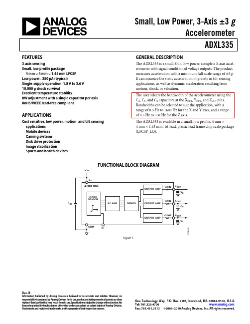
Small, Low Power, 3-Axis ±3 gAccelerometerADXL335Rev. BInformation furnished by Analog Devices is believed to be accurate and reliable. However , no responsibility is assumed by Analog Devices for its use, nor for any infringements of patents or other rights of third parties that may result from its use. Specifications subject to change without notice. No license is granted by implication or otherwise under any patent or patent rights of Analog Devices. T rademarks and registered trademarks are the property of their respective owners.One Technology Way, P.O. Box 9106, Norwood, M A 02062-9106, U.S.A.Tel: 781.329.4700 Fax: 781.461.3113 ©2009–2010 Analog Devices, Inc. All rights reserved.FEATURES3-axis sensingSmall, low profile package4 mm × 4 mm × 1.45 mm LFCSP Low power : 350 μA (typical)Single-supply operation: 1.8 V to 3.6 V 10,000 g shock survivalExcellent temperature stabilityBW adjustment with a single capacitor per axis RoHS/WEEE lead-free compliantAPPLICATIONSCost sensitive, low power, motion- and tilt-sensing applications Mobile devices Gaming systemsDisk drive protection Image stabilizationSports and health devicesGENERAL DESCRIPTIONThe ADXL335 is a small, thin, low power, complete 3-axis accel-erometer with signal conditioned voltage outputs. The product measures acceleration with a minimum full-scale range of ±3 g . It can measure the static acceleration of gravity in tilt-sensing applications, as well as dynamic acceleration resulting from motion, shock, or vibration.The user selects the bandwidth of the accelerometer using the C X , C Y , and C Z capacitors at the X OUT , Y OUT , and Z OUT pins. Bandwidths can be selected to suit the application, with a range of 0.5 Hz to 1600 Hz for the X and Y axes, and a range of 0.5 Hz to 550 Hz for the Z axis.The ADXL335 is available in a small, low profile, 4 mm ×4 mm × 1.45 mm, 16-lead, plastic lead frame chip scale package (LFCSP_LQ).FUNCTIONAL BLOCK DIAGRAMC DCFigure 1.ADXL335Rev. B | Page 2 of 16TABLE OF CONTENTSFeatures .............................................................................................. 1 Applications ....................................................................................... 1 General Description ......................................................................... 1 Functional Block Diagram .............................................................. 1 Revision History ............................................................................... 2 Specifications ..................................................................................... 3 Absolute Maximum Ratings ............................................................ 4 ESD Caution .................................................................................. 4 Pin Configuration and Function Descriptions ............................. 5 Typical Performance Characteristics ............................................. 6 Theory of Operation ...................................................................... 10 Mechanical Sensor ...................................................................... 10 Performance ................................................................................ 10 Applications Information .............................................................. 11 Power Supply Decoupling ......................................................... 11 Setting the Bandwidth Using C X , C Y , and C Z .......................... 11 Self-Test ....................................................................................... 11 Design Trade-Offs for Selecting Filter Characteristics: The Noise/BW Trade-Off .................................................................. 11 Use with Operating V oltages Other Than 3 V ........................... 12 Axes of Acceleration Sensitivity ............................................... 12 Layout and Design Recommendations ................................... 13 Outline Dimensions ....................................................................... 14 Ordering Guide .. (14)REVISION HISTORY1/10—Rev. A to Rev. BChanges to Figure 21 (9)7/09—Rev. 0 to Rev. AChanges to Figure 22 ........................................................................ 9 Changes to Outline Dimensions (14)1/09—Revision 0: Initial VersionADXL335Rev. B | Page 3 of 16SPECIFICATIONST A = 25°C, V S = 3 V , C X = C Y = C Z = 0.1 μF, acceleration = 0 g , unless otherwise noted. All minimum and maximum specifications are guaranteed. Typical specifications are not guaranteed. Table 1.Parameter Conditions M in Typ M ax Unit SENSOR INPUT Each axisMeasurement Range ±3 ±3.6g Nonlinearity % of full scale ±0.3 % Package Alignment Error ±1 Degrees Interaxis Alignment Error ±0.1 DegreesCross-Axis Sensitivity 1±1 % SENSITIVITY (RATIOMETRIC)2 Each axis Sensitivity at X OUT , Y OUT , Z OUT V S = 3 V 270 300 330 mV/gSensitivity Change Due to Temperature 3V S = 3 V ±0.01 %/°C ZERO g BIAS LEVEL (RATIOMETRIC) 0 g Voltage at X OUT , Y OUT V S = 3 V 1.35 1.5 1.65 V 0 g Voltage at Z OUT V S = 3 V 1.2 1.5 1.8 V 0 g Offset vs. Temperature ±1 m g /°C NOISE PERFORMANCE Noise Density X OUT , Y OUT 150 μg /√Hz rms Noise Density Z OUT 300 μg /√Hz rms FREQUENCY RESPONSE 4 Bandwidth X OUT , Y OUT 5 No external filter 1600 Hz Bandwidth Z OUT 5 No external filter 550 Hz R FILT Tolerance 32 ± 15% kΩ Sensor Resonant Frequency 5.5 kHz SELF-TEST 6 Logic Input Low +0.6 V Logic Input High +2.4 V ST Actuation Current +60 μA Output Change at X OUT Self-Test 0 to Self-Test 1 −150 −325 −600 mV Output Change at Y OUT Self-Test 0 to Self-Test 1 +150 +325 +600 mV Output Change at Z OUT Self-Test 0 to Self-Test 1 +150 +550 +1000 mV OUTPUT AMPLIFIER Output Swing Low No load 0.1 V Output Swing High No load 2.8 V POWER SUPPLY Operating Voltage Range 1.8 3.6 V Supply Current V S = 3 V 350 μA Turn-On Time 7 No external filter 1 ms TEMPERATURE Operating Temperature Range −40 +85 °C1 Defined as coupling between any two axes. 2Sensitivity is essentially ratiometric to V S . 3Defined as the output change from ambient-to-maximum temperature or ambient-to-minimum temperature. 4Actual frequency response controlled by user-supplied external filter capacitors (C X , C Y , C Z ). 5Bandwidth with external capacitors = 1/(2 × π × 32 kΩ × C). For C X , C Y = 0.003 μF, bandwidth = 1.6 kHz. For C Z = 0.01 μF, bandwidth = 500 Hz. For C X , C Y , C Z = 10 μF, bandwidth = 0.5 Hz. 6Self-test response changes cubically with V S . 7Turn-on time is dependent on C X , C Y , C Z and is approximately 160 × C X or C Y or C Z + 1 ms, where C X , C Y , C Z are in microfarads (μF).ADXL335Rev. B | Page 4 of 16ABSOLUTE MAXIMUM RATINGSTable 2.Parameter Rating Acceleration (Any Axis, Unpowered) 10,000 g Acceleration (Any Axis, Powered) 10,000 g V S −0.3 V to +3.6 V All Other Pins (COM − 0.3 V) to (V S + 0.3 V)Output Short-Circuit Duration(Any Pin to Common)Indefinite Temperature Range (Powered) −55°C to +125°C Temperature Range (Storage) −65°C to +150°CStresses above those listed under Absolute Maximum Ratings may cause permanent damage to the device. This is a stress rating only; functional operation of the device at these or any other conditions above those indicated in the operationalsection of this specification is not implied. Exposure to absolute maximum rating conditions for extended periods may affect device reliability.ESD CAUTIONADXL335Rev. B | Page 5 of 16PIN CONFIGURATION AND FUNCTION DESCRIPTIONS07808-003NOTES1. EXPOSED PAD IS NOT INTERNALLYCONNECTED BUT SHOULD BE SOLDERED FOR MECHANICAL INTEGRITY.NC = NO CONNECTNCST COM NCX OUT NC Y OUT NCC O MC O MC O MZ O U TN CV SV SN CFigure 2. Pin ConfigurationTable 3. Pin Function DescriptionsPin No. MnemonicDescription1 NC No Connect.12 ST Self-Test.3 C O M Common.4 NC No Connect.15 C O M Common.6 C O M Common.7 C O M Common.8 Z OUTZ Channel Output.9 NC No Connect.110 Y OUTY Channel Output.11 NC No Connect. 112 X OUTX Channel Output.13 NC No Connect. 114 V S Supply Voltage (1.8 V to 3.6 V). 15 V SSupply Voltage (1.8 V to 3.6 V).16 NC No Connect. 1EP Exposed PadNot internally connected. Solder for mechanical integrity.1NC pins are not internally connected and can be tied to COM pins, unless otherwise noted.ADXL335Rev. B | Page 6 of 16TYPICAL PERFORMANCE CHARACTERISTICSN > 1000 for all typical performance plots, unless otherwise noted.500102030401.42 1.44 1.46 1.48 1.50 1.52 1.54 1.56 1.58% O F P O P U L A T I O NOUTPUT (V)07808-005Figure 3. X-Axis Zero g Bias at 25°C, V S = 3 V500102030401.42 1.44 1.46 1.48 1.50 1.52 1.54 1.56 1.58% O F P O P U L A T I O NOUTPUT (V)07808-006Figure 4. Y-Axis Zero g Bias at 25°C, V S = 3 V1.42 1.44 1.46 1.48 1.50 1.52 1.54 1.56 1.58% O F P O P U L A T I O NOUTPUT (V)07808-0070510152025Figure 5. Z-Axis Zero g Bias at 25°C, V S = 3 V % O F P O P U L A T I O NVOLTS (V)07808-00810203040–0.40–0.38–0.36–0.34–0.32–0.30–0.28–0.26Figure 6. X-Axis Self-Test Response at 25°C, V S = 3 V% O F P O P U L A T I O NVOLTS (V)07808-00910203050400.260.280.300.320.340.360.380.40Figure 7. Y-Axis Self-Test Response at 25°C, V S = 3 V% O F P O P U L A T I O NVOLTS (V)07808-010102030400.480.500.520.540.560.580.600.62Figure 8. Z-Axis Self-Test Response at 25°C, V S = 3 VADXL335Rev. B | Page 7 of 16% O F P O P U L A T I O NTEMPERATURE COEFFICIENT (m g/°C)51015202530–3.0–2.5–2.0–1.5–1.0–0.500.5 1.0 1.5 2.0 2.5 3.007808-011Figure 9. X-Axis Zero g Bias Temperature Coefficient, V S = 3 V% O F P O P U L A T I O NTEMPERATURE COEFFICIENT (m g /°C)10204030–3.0–2.5–2.0–1.5–1.0–0.500.5 1.0 1.5 2.0 2.53.007808-012Figure 10. Y-Axis Zero g Bias Temperature Coefficient, V S = 3 V% O F P O P U L A T I O NTEMPERATURE COEFFICIENT (m g/°C)510152007808-013Figure 11. Z-Axis Zero g Bias Temperature Coefficient, V S = 3 V1.451.461.471.481.491.501.511.521.531.541.55TEMPERATURE (°C)O U T P U T (V )07808-014Figure 12. X-Axis Zero g Bias vs. Temperature—Eight Parts Soldered to PCB1.451.461.471.481.491.501.511.521.531.541.55–40–30–20–100102030405060708090100TEMPERATURE (°C)O U T P U T (V )07808-015Figure 13. Y-Axis Zero g Bias vs. Temperature—Eight Parts Soldered to PCB1.301.321.341.361.381.401.421.441.461.481.50–40–30–20–100102030405060708090100TEMPERATURE (°C)O U T P U T (V )07808-016Figure 14. Z-Axis Zero g Bias vs. Temperature—Eight Parts Soldered to PCBADXL335Rev. B | Page 8 of 16% O F P O P U L A T I O NSENSITIVITY (V/g )51015200.2850.2880.2910.2940.2970.3000.3030.3060.3090.3120.31507808-017Figure 15. X-Axis Sensitivity at 25°C, V S = 3 V% O F P O P U L A T I O NSENSITIVITY (V/g )051015200.2850.2880.2910.2940.2970.3000.3030.3060.3090.3120.3152507808-018Figure 16. Y-Axis Sensitivity at 25°C, V S = 3 V% O F P O P U L A T I O NSENSITIVITY (V/g )51015202507808-019Figure 17. Z-Axis Sensitivity at 25°C, V S= 3 V0.2800.2850.2900.2950.3000.3050.3100.3150.320TEMPERATURE (°C)S E N S I T I V I T Y (V /g )07808-020Figure 18. X-Axis Sensitivity vs. Temperature—Eight Parts Soldered to PCB, V S= 3 V0.2800.2850.2900.2950.3000.3050.3100.3150.320–40–30–20–100102030405060708090100TEMPERATURE (°C)S E N S I T I V I T Y (V /g )07808-021Figure 19. Y-Axis Sensitivity vs. Temperature—Eight Parts Soldered to PCB, V S= 3 V0.2800.2850.2900.2950.3000.3050.3100.3150.320–40–30–20–100102030405060708090100TEMPERATURE (°C)S E N S I T I V I T Y (V /g )07808-022Figure 20. Z-Axis Sensitivity vs. Temperature—Eight Parts Soldered to PCB, V S = 3 VADXL335Rev. B | Page 9 of 16SUPPLY (V)C U R R E N T (µA )0100501502002503003501.52.0 2.53.0 3.54.007808-023Figure 21. Typical Current Consumption vs. Supply VoltageTIME (1ms/DIV)07808-024Figure 22. Typical Turn-On Time, V S = 3 VADXL335Rev. B | Page 10 of 16THEORY OF OPERATIONThe ADXL335 is a complete 3-axis acceleration measurement system. The ADXL335 has a measurement range of ±3 g mini-mum. It contains a polysilicon surface-micromachined sensor and signal conditioning circuitry to implement an open-loop acceleration measurement architecture. The output signals are analog voltages that are proportional to acceleration. The accelerometer can measure the static acceleration of gravity in tilt-sensing applications as well as dynamic acceleration resulting from motion, shock, or vibration.The sensor is a polysilicon surface-micromachined structure built on top of a silicon wafer. Polysilicon springs suspend the structure over the surface of the wafer and provide a resistance against acceleration forces. Deflection of the structure is meas-ured using a differential capacitor that consists of independent fixed plates and plates attached to the moving mass. The fixed plates are driven by 180° out-of-phase square waves. Acceleration deflects the moving mass and unbalances the differential capacitor resulting in a sensor output whose amplitude is proportional to acceleration. Phase-sensitive demodulation techniques are then used to determine the magnitude and direction of the acceleration. The demodulator output is amplified and brought off-chip through a 32 kΩ resistor. The user then sets the signalbandwidth of the device by adding a capacitor. This filtering improves measurement resolution and helps prevent aliasing.MECHANICAL SENSORThe ADXL335 uses a single structure for sensing the X, Y, and Z axes. As a result, the three axes’ sense directions are highly orthogonal and have little cross-axis sensitivity. Mechanical misalignment of the sensor die to the package is the chief source of cross-axis sensitivity. Mechanical misalignment can, of course, be calibrated out at the system level.PERFORMANCERather than using additional temperature compensation circui-try, innovative design techniques ensure that high performance is built in to the ADXL335. As a result, there is no quantization error or nonmonotonic behavior, and temperature hysteresis is very low (typically less than 3 m g over the −25°C to +70°C temperature range).ADXL335 APPLICATIONS INFORMATIONPOWER SUPPLY DECOUPLINGFor most applications, a single 0.1 μF capacitor, C DC, placedclose to the ADXL335 supply pins adequately decouples the accelerometer from noise on the power supply. However, in applications where noise is present at the 50 kHz internal clock frequency (or any harmonic thereof), additional care in power supply bypassing is required because this noise can cause errorsin acceleration measurement.If additional decoupling is needed, a 100 Ω (or smaller) resistoror ferrite bead can be inserted in the supply line. Additionally, a larger bulk bypass capacitor (1 μF or greater) can be added in parallel to C DC. Ensure that the connection from the ADXL335 ground to the power supply ground is low impedance becausenoise transmitted through ground has a similar effect to noise transmitted through V S.SETTING THE BANDWIDTH USING C X, C Y, AND C ZThe ADXL335 has provisions for band limiting the X OUT, Y OUT,and Z OUT pins. Capacitors must be added at these pins to imple-ment low-pass filtering for antialiasing and noise reduction. The equation for the 3 dB bandwidth isF−3 dB = 1/(2π(32 kΩ) × C(X, Y, Z))or more simplyF–3 dB = 5 μF/C(X, Y, Z)The tolerance of the internal resistor (R FILT) typically varies asmuch as ±15% of its nominal value (32 kΩ), and the bandwidth varies accordingly. A minimum capacitance of 0.0047 μF for C X,C Y, and C Z is recommended in all cases.Table 4. Filter Capacitor Selection, C X, C Y, and C ZBandwidth (Hz) Capacitor (μF)1 4.7 10 0.47 50 0.10 100 0.05 200 0.027 500 0.01SELF-TESTThe ST pin controls the self-test feature. When this pin is set toV S, an electrostatic force is exerted on the accelerometer beam.The resulting movement of the beam allows the user to test ifthe accelerometer is functional. The typical change in outputis −1.08 g (corresponding to −325 mV) in the X-axis, +1.08 g(or +325 mV) on the Y-axis, and +1.83 g (or +550 mV) on theZ-axis. This ST pin can be left open-circuit or connected tocommon (COM) in normal use. Never expose the ST pin to voltages greater than V S + 0.3 V.If this cannot be guaranteed due to the system design (for instance, if there are multiple supply voltages), then a lowV F clamping diode between ST and V S is recommended. DESIGN TRADE-OFFS FOR SELECTING FILTER CHARACTERISTICS: THE NOISE/BW TRADE-OFF The selected accelerometer bandwidth ultimately determines the measurement resolution (smallest detectable acceleration). Filtering can be used to lower the noise floor to improve the resolution of the accelerometer. Resolution is dependent on the analog filter bandwidth at X OUT, Y OUT, and Z OUT.The output of the ADXL335 has a typical bandwidth of greater than 500 Hz. The user must filter the signal at this point to limit aliasing errors. The analog bandwidth must be no more than half the analog-to-digital sampling frequency to minimize aliasing. The analog bandwidth can be further decreased to reduce noise and improve resolution.The ADXL335 noise has the characteristics of white Gaussian noise, which contributes equally at all frequencies and is described in terms of μg/√Hz (the noise is proportional to the square root of the accelerometer bandwidth). The user should limit bandwidth to the lowest frequency needed by the applica-tion to maximize the resolution and dynamic range of the accelerometer.With the single-pole, roll-off characteristic, the typical noise of the ADXL335 is determined by)1.6(××=BWDensityNoiseNoisermsIt is often useful to know the peak value of the noise. Peak-to-peak noise can only be estimated by statistical methods. Table 5 is useful for estimating the probabilities of exceeding various peak values, given the rms value.Table 5. Estimation of Peak-to-Peak NoisePeak-to-Peak Value% of Time That Noise ExceedsNominal Peak-to-Peak Value2 × rms 324 × rms 4.66 × rms 0.278 × rms 0.006ADXL335USE WITH OPERATING VOLTAGES OTHER THAN 3 VThe ADXL335 is tested and specified at V S = 3 V; however, it can be powered with V S as low as 1.8 V or as high as 3.6 V . Note that some performance parameters change as the supply voltage is varied.The ADXL335 output is ratiometric, therefore, the output sensitivity (or scale factor) varies proportionally to the supply voltage. At V S = 3.6 V , the output sensitivity is typi- cally 360 mV/g . At V S = 2 V , the output sensitivity is typically 195 mV/g .The zero g bias output is also ratiometric, thus the zero g output is nominally equal to V S /2 at all supply voltages. The output noise is not ratiometric but is absolute in volts; therefore, the noise density decreases as the supply voltage increases. This is because the scale factor (mV/g ) increases while the noise voltage remains constant. At V S = 3.6 V , the X-axis and Y-axis noise density is typically 120 μg /√Hz, whereas at V S = 2 V , the X-axis and Y-axis noise density is typically 270 μg /√Hz.Self-test response in g is roughly proportional to the square of the supply voltage. However, when ratiometricity of sensitivity is factored in with supply voltage, the self-test response in volts is roughly proportional to the cube of the supply voltage. For example, at V S = 3.6 V , the self-test response for the ADXL335 is approximately −560 mV for the X-axis, +560 mV for the Y-axis, and +950 mV for the Z-axis.At V S = 2 V , the self-test response is approximately −96 mV for the X-axis, +96 mV for the Y-axis, and −163 mV for the Z-axis. The supply current decreases as the supply voltage decreases. Typical current consumption at V S = 3.6 V is 375 μA, and typi-cal current consumption at V S = 2 V is 200 μA.AXES OF ACCELERATION SENSITIVITYA X07808-025Figure 23. Axes of Acceleration Sensitivity; Corresponding Output VoltageIncreases When Accelerated Along the Sensitive Axis.X OUT = –1g Y OUT = 0g Z= 0gGRAVITYX OUT = 0g Y OUT = 1g Z OUT = 0gX OUT = 0g Y OUT = –1g Z OUT = 0gX OUT = 1g YOUT = 0gZ OUT = 0gX OUT = 0g Y OUT = 0g Z OUT = 1g X OUT = 0g Y OUT = 0g Z OUT = –1g07808-026Figure 24. Output Response vs. Orientation to GravityADXL335LAYOUT AND DESIGN RECOMMENDATIONSThe recommended soldering profile is shown in Figure 25 followed by a description of the profile features in Table 6. The recommended PCB layout or solder land drawing is shown in Figure 26.07808-002T E M P E R A T U R ETIMETFigure 25. Recommended Soldering ProfileTable 6. Recommended Soldering ProfileProfile Feature Sn63/Pb37 Pb-Free Average Ramp Rate (T L to T P ) 3°C/sec max 3°C/sec maxPreheat Minimum Temperature (T SMIN ) 100°C 150°C Maximum Temperature (T SMAX ) 150°C 200°C Time (T SMIN to T SMAX )(t S ) 60 sec to 120 sec 60 sec to 180 sec T SMAX to T L Ramp-Up Rate 3°C/sec max 3°C/sec max Time Maintained Above Liquidous (T L ) Liquidous Temperature (T L ) 183°C 217°C Time (t L ) 60 sec to 150 sec 60 sec to 150 sec Peak Temperature (T P ) 240°C + 0°C/−5°C 260°C + 0°C/−5°C Time Within 5°C of Actual Peak Temperature (t P ) 10 sec to 30 sec 20 sec to 40 sec Ramp-Down Rate 6°C/sec max 6°C/sec max Time 25°C to Peak Temperature 6 minutes max 8 minutes max0.35DIMENSIONS SHOWN IN MILLIMETERS07808Figure 26. Recommended PCB LayoutADXL335OUTLINE DIMENSIONS051909-A1.500.08PIN COMPLIANT TO JEDEC STANDARDS MO-220-WGGD.FOR PROPER CONNECTION OF THE EXPOSED PAD,REFER TO THE PIN CONFIGURATION AND FUNCTION DESCRIPTIONSSECTION OF THIS DATA SHEET.Figure 27. 16-Lead Lead Frame Chip Scale Package [LFCSP_LQ]4 mm × 4 mm Body, 1.45 mm Thick Quad(CP-16-14)Dimensions shown in millimetersORDERING GUIDEModel 1 M easurement Range Specified Voltage Temperature Range Package Description Package OptionADXL335BCPZ ±3 g 3 V −40°C to +85°C 16-Lead LFCSP_LQ CP-16-14 ADXL335BCPZ–RL ±3 g 3 V −40°C to +85°C 16-Lead LFCSP_LQ CP-16-14 ADXL335BCPZ–RL7 ±3 g 3 V −40°C to +85°C 16-Lead LFCSP_LQ CP-16-14 EVAL-ADXL335ZEvaluation Board1Z = RoHS Compliant Part.ADXL335 NOTESADXL335NOTESAnalog Devices offers specific products designated for automotive applications; please consult your local Analog Devices sales representative for details. Standard products sold by Analog Devices are not designed, intended, or approved for use in life support, implantable medical devices, transportation, nuclear, safety, or other equipment where malfunction of the product can reasonably be expected to result in personal injury, death, severe property damage, or severe environmental harm. Buyer uses or sells standard products for use in the above critical applications at Buyer's own risk and Buyer agrees to defend, indemnify, and hold harmless Analog Devices from any and all damages, claims, suits, or expenses resulting from such unintended use.©2009–2010 Analog Devices, Inc. All rights reserved. Trademarks andregistered trademarks are the property of their respective owners.D07808-0-1/10(B)。
DFK 33GP1300e 技术手册说明书
技术细节1.要件速览 42.尺寸图 6 2.1DFK 33GP1300e 带脚架适配器的C型接口 (6)2.2DFK 33GP1300e 不带脚架适配器的C型接口 (7)2.3DFK 33GP1300e 带脚架适配器的CS型接口 (8)2.4DFK 33GP1300e 不带脚架适配器的CS型接口 (9)3.I/O 连接器 10 3.16-pin I/O 连接器 (10)3.1.1TRIGGER_IN (10)3.1.2STROBE_OUT (11)4.光谱特征 12 4.1红外截止滤波器 (12)4.2光谱灵敏度 - P1300 (12)5.相机控制 13 5.1传感器读出控制 (13)5.1.1像素格式 (13)8-Bit Bayer Raw (13)5.1.1.15.1.1.212-Bit Packed Bayer Raw (14)16-Bit Bayer Raw (14)5.1.1.35.1.1.4YUV 4:2:2 (14)5.1.1.5YUV 4:1:1 (14)5.1.1.6RGB24 (14)5.1.2分辨率 (15)5.1.3读出模式 (15)帧速率 (16)5.1.45.1.5局部扫描偏移 (17)5.2图像传感器控制 (18)5.2.1曝光时间 (18)5.2.2增益 (18)5.3自动曝光及增益控制 (19)5.3.1自动曝光 (19)自动增益 (19)5.3.25.3.3自动参考值 (20)5.3.4强光缩减 (20)5.3.5自动曝光限制 (20)5.3.6自动增益限制 (21)5.4触发 (21)触发模式 (21)5.4.15.4.2触发极性 (22)5.4.3软件触发 (22)5.4.4触发脉冲计数 (22)5.4.5触发源 (23)5.4.6触发重叠 (23)5.5触发定时参数 (23)触发延迟 (23)5.5.15.5.2触发去抖时间 (24)5.5.3触发遮罩时间 (24)5.5.4触发噪声抑制时间 (24)5.6数字I/O (25)5.6.1通用输入 (25)5.6.2通用输出 (25)5.7频闪 (26)5.7.1频闪启用 (26)5.7.2频闪极性 (26)频闪操作 (26)5.7.35.8白平衡 (26)5.8.1自动白平衡 (27)5.8.2白平衡模式 (27)5.8.3手动白平衡 (28)5.9图像处理 (29)5.9.1伽玛 (29)5.9.2查找表 (30)5.10色彩处理 (31)色调 (31)5.10.15.10.2饱和 (31)5.10.3色彩校正矩阵 (32)5.11自动功能感兴趣的区域 (34)5.11.1自动功能ROI启用 (34)5.11.2自动功能ROI预设 (34)5.11.3自动功能ROI自定义矩形 (35)5.12用户设置 (36)用户设置选择器 (36)5.12.15.12.2加载用户设置 (36)5.12.3保存用户设置 (36)默认用户配置 (37)5.12.46.R e v i s i o n H i story 381要件速览2尺寸图2.1DFK 33GP1300e 带脚架适配器的C型接口2.4DFK 33GP1300e 不带脚架适配器的CS型接口3I/O 连接器3.16-pin I/O 连接器相机后视图1开极闸M OS F E T最大限制0.2A(ID)!2启动电流最低条件3.5mA!3 G:地O:输出I:输入3.1.1TR IGG ER_I NTRIGGER_IN线可用于将曝光时间的开始与外部事件同步。
无线倾角传感器NB系列V3.0协议手册说明书

NB系列无线倾角传感器协议手册调试方法可以使用本公司开发的网络串口助手(UDP)网络串口助手(UDP)使用步骤:1、打开网络串口助手(UDP);2、输入监听IP(打开软件后可自动获取),监听IP为云端服务器的IP地址(此IP为局域网本机IP,要与云端服务器所连接的公网静态IP映射到一起);3、输入端口号(默认8887),此端口号与无线传感器端设置的端口号一致(注意确保此端口号没有被其它软件占用)。
4、设置存储路径及文件名,设置自动存储间隔时间,勾选存储;5、点击启动。
注:图中的时间由网络串口助手手添加非无线传感器发送。
数据分析服务器接收端收到的数据为ASCII码,表示为:传感器端IP地址及端口号传感器地址+X轴角度+Y轴角度+ Z轴角度+X轴加速度+Y轴加速度+Z轴加速度+温度+电池电量+电话号码218.204.253.18:57234100000005,+003.4982,+000.5570,+086.4531,+000.0601,+000.0097,+000.9823,027.0000,9,144003393 1560 218.204.253.18:57234对应传感器端IP地址及端口号(每次由移动公司随机分配);100000005对应无线传感器模块地址+003.4982,+000.5570,+086.4531分别对应:X轴角度Y轴角度Z轴角度,单位°+000.0601,+000.0097,+000.9823分别对应:X轴加速度Y轴加速度Z轴加速度,单位g+027.0000对应传感器温度:27℃;9代表电池电量,范围0~9,电量最高为9(满电状态),最低0(需要充电);1440033931560为电话号码;数据格式:100000005,+003.4982,+000.5570,+086.4531,+000.0601,+000.0097,+000.9823,+027.0000,9,1440033931560传感器地址X轴角度Y轴角度Z轴角度X轴加速度Y轴加速度Z轴加速度温度电池电量电话号码参数设置1、客户可以设置地址、相对零点、休眠时间、IP地址及端口号等参数;2、通信接口TTL ,波特率9600;3、调试软件可在本公司官网下载iCOM串口调试助手或WL调试助手;下图通用串口助手的设置,注意勾选发送新行4、发送设置选择ASCLL发送5、接收设置选择ASCLL接收6、底部勾选发送新行参数命令1、开启设置命令(开机20s内发两次)发送:SENSOR+SET返回:201808031OK2、设置地址:(1为设置地址的功能码,201808031为地址)发送:SET+1+201808031返回:SET+1+201808031OK3、设置休眠时间:(2为设置休眠时间的功能码,30为休眠时间,单位:分钟,范围1~99999)发送:SET+2+30 返回:SET+2+30OK4、设置IP及端口号:(4为设置IP及端口号的功能码,39.105.2.44为IP,12000为端口号(范围0~99999))发送:SET+4+,39.105.2.44,12000,返回:SET+4+,39.105.2.44,12000,OK注:此处设置的IP地址为云端服务器的公网静态IP,在云端服务器接收数据时,要将此IP与网络串口助手(UDP)自动获取的云端服务器本机局域网IP映射到一起。
CA30CAN CAF 4TH 代三重保护电容接近传感器说明书

Proximity Sensors Capacitive Thermoplastic Polyester Housing Types CA30CAN/CAF.....• 4TH Generation TRIPLESHIELD TM• Adjustable sensing distance: 2 - 20 mm Flush or 4-30 mm Non-flush• Protection: short-circuit, transients and reverse polarity • Dust and humidity compensation • Dust or Temperature alarm output • Rated operational voltage: 10-40 VDC • Output: DC 200 mA, NPN or PNP • Standard Output: NO and NC• LED indications for Power-supply, Output and Stability • IP67, IP68, IP69K, Nema 1, 2, 4, 4X, 5, 6, 6P, 12• Cable and M12 connector versions availableProduct DescriptionThe CA30CA.. capacitive proximity switches feature an improved 4TH Genera-tion TRIPLESHIELD TM tech-nology. F urthermore, these sensors feature increased immunity to electromagnetic inteference (EMI), especial-ly to frequency drives. Not only does 4TH Generation TRIPLESHIELD TM feature an increased EMI, but it also increases the immuni-ty to humidity and dust. The implementation of stability indication eases the setup procedure as both Stable ON and Stable OFF positions are indicated by the Green and yellow LEDs.increased by 20 – 25 % allowing room for additional stable detection.gives an early warning that have to be cleaned.The Temperature alarm func-tion raises an alarm if the sensing surface goes beyond 60 degree celcius.The sensor housing is featur-ing IP69K as well as approval by ECOLAB for cleaning- and disinfection agents.Rated operating distance (S n ) Non-flush mounted sensor 0 - 25 mm (factory setting 25 mm), (ref. target 75x75 mm ST37, 1 mm thick, grounded) Flush mounted sensor 0 - 16 mm (factory setting 16 mm - non-flush mounted) (ref. target 48x48 mm ST37, 1 mm thick, grounded)Specifications EN 60947-5-2Housing Sensor Output Output ConnectionRated operating Ordering no. Ordering no. Ordering no.diameter type type function distance (S n ) StandardDust alarmTemperature alarmM 30 Flush NPN NO+NC Cable 0 - 16 mm CA30CAF16NA M 30 Flush NPN NO+NC M12 Plug 0 - 16 mm CA30CAF16NAM1M 30 Flush PNP NO+NC Cable 0 - 16 mm CA30CAF16PA M 30 Flush PNP NO+NC M12 Plug 0 - 16 mm CA30CAF16PAM1M 30 Flush PNP NO Cable 0 - 16 mm CA30CAF16PODU CA30CAF16POTAM 30 Flush PNP NC Cable 0 - 16 mmCA30CAF16PCDU CA30CAF16PCTA M 30 Flush PNP NC M12 Plug 0 - 16 mm CA30CAF16PCM1DUM 30 Non-Flush NPN NO+NC Cable 0 - 25 mm CA30CAN25NA M 30 Non-Flush NPN NO+NC M12 Plug 0 - 25 mm CA30CAN25NAM1M 30 Non-Flush PNP NO+NC Cable 0 - 25 mm CA30CAN25PA M 30 Non-Flush PNP NO+NC M12 Plug 0 - 25 mm CA30CAN25PAM1M 30 Non-Flush PNP NO Cable 0 - 25 mm CA30CAN25PODU CA30CAN25POTA M 30Non-FlushPNPNCCable0 - 25 mmCA30CAN25PCDU CA30CAN25PCTAType SelectionCA30CAN/CAF.....Specifications (cont.) EN 60947-5-2* The IP69K test according to DIN 40050-9 for high-pressure, high-temperature wash-down applications. The sensor must not only be dust tight (IP6X), but also able to withstand high-pressure and steam cleaning. The sensor is exposed to high pressure water from a spray nozzle that is fed with 80°C water at 8’000– 10’000 KPa (80–100bar) and a flow rate of 14–6L/min. The nozzle is held 100 –150 mm from the sensor at angles of 0°, 30°, 60° and 90° for 30s each. The test device sits on a turntable that rotates with a speed of 5 times per minute. The sensor must not suffer any damaging effects from the high pressure water in appear-ance and function.90°60°30°0°The environments in which capacitive sensors are in s tall e d can often be un s ta-ble as regards to tempera-ture, humi d ity , object dis-tance and industrial (noise) inter f erence. Because of this, Carlo Ga v azzi offers as standard features in all TRIPLESHIELD TM capacitive sensors a user-friendly sen-sitivity adjustment instead of a fixed sensing range. Likewise, these sensors provide an extend e d sen-sing range to accommodatemechanically de m and i ng are-as and tem p erature stability to en s ure high immunity to elec t ro m agnetic interference (EMI) and a minimum need for adjusting sensitivity if the temperature varies.Note:Sensors are factory set (default) to nominal sensing range S n .Adjustment GuideCA30CAN/CAF.....Wiring DiagramDetection DiagramCA30CAN/CAF.....Detection Stability IndicationDimensionsInstallation HintsCapacitive sensors have a unique ability to detect al-most any material in li q uid or solid form. Capa c i t ive sen-sors are able to detect me-tallic as well as non-metallic ob j ects. How e ver, their tradi-tional use is for non-metallic materials such as:• Plastics Industry Resins, regrinds or mould-ed products.• Chemical IndustryCleansers, fertilizers, liq-uid soaps, corrosives andpe t r o c hemicals.• Wood IndustrySaw dust, paper products,door and window frames.• Ceramics & GlassI ndustryRaw materials, clay orfinish e d products, bottles.• Packaging IndustryPackage inspection for lev-el or contents, dry goods,fruits and vegetables, dairyproducts.Materials are detected due totheir dielectric constant. Thebigger the size of an object,the higher the density of ma-terial, the better or easier it isto detect the object.The nominal sensing di s tan-ce for a capacitive sensoris refe r r ed to a groundedme t al plate (ST37). For addi-tional information regardingdi e lec t ric ratings of materi-als please re f er to TechnicalInformation.Relief of cable strain Protection of the sensing face Switch mounted on mobile carrier To avoid interference from inductive voltage/current peaks, separate the prox. switch pow-er cables from any other power cables, e.g.motor, contactor or solenoid cablesNot correctCorrectThe cable should not be pulled A proximity switch should not serve asmechanical stopAny repetitive flexing of thecable should be avoided Delivery Contents•Capacitive switch: CA30CAN/CAF.......• User manual• 2 x M30 fingernuts• Screwdriver• Packaging: Cardboard boxAccessories• Connector type CONM14NF.. -series.• Mounting Brackets AMB30-S.. (straight),AMB30-A.. (angled)CA30CAN/CAF.....。
切尔哈姆合光电感应传感器E58-30系列用户手册说明书

Models covered in this manual:AC/DC Models w/ CableAC/DC Models w/ ConnectorDC-only Models w/ CableDC-only Models w/ ConnectorLight Operate Dark Operate Light Operate Dark Operate Light Operate Dark Operate Light Operate Dark Operate PolarizedE58-30RP10-GLE58-30RP10-GDE58-30RP10-GLPE58-30RP10-GDPE58-30RP10-HLE58-30RP10-HDE58-30RP10-HLPE58-30RP10-HDPInstallation Instructions—E58-30 Series Polarized Reflex Sensors Document 108623-400 Rev 02Cutler-Hammer Photoelectric SensorsWARNING!•These products are not designed, tested, or recommended for use in human safety applications.•This product has no user-serviceable parts—please return to the factory for repairs. The cable clamp on the back of the sensor does not require adjustment. Any attempt to tighten or loosen this part will compromise sealing and void warranty.•AC/DC connector version sensors are equipped with an AC-type connector. The use of DC power with AC-type connectors may not conform with established standards.D C 10 t o 30 V*Note: No connection when using thru-beam sources+V( - )D C 15 t o 30 V*Note: No connection when using thru-beam sources+VAC/DC Models (DC Connection, see Warning above)DC ModelsWIRING DIAGRAMSFor wiring cable versions, the color codes shown are the actual wire colors emanating from the sensor. For connector versions, the pin numbering and color codes shown are typical of several manufacturers, however, variations are possible. In case of discrepancies, rely on function indicated and pin location rather than pin number or color code.AC/DC Models (AC Connection)A C 20 t o 264 V*Note: No connection when using thru-beam sources L1L2REFLEX SENSINGA reflex sensor has both a light source and detector in the same unit. The source sends a beam of light to a retroreflector which returns it back to the detector. A break in the light beam causes the sensor to change output state.The polarizing filter conditions the beam so that light reflected off the retroreflector is detected,but light reflected by the target is not. This ensures reliable detection of shiny targets.MOUNTING LOCATION AND SET-UPLocate the sensor and retroreflector onopposite sides of the target. Ensure that the area of the target to be detected will block the entire effective beam.With power applied to the sensor, aim the unit directly at the center of the retroreflector. Move the sensor back and forth in one plane to find the extreme positions where the output indicator goes “off” (for light-operate mode, or “on” for dark-operate mode). Position the sensor midway between the two extremes.Repeat this procedure for the other plane. After alignment, tighten all mounting screws. An alternate method is to look at the retroreflector with your eye as close to the sensor as possible and align the sensor until reflected light is brightest.Stretch wrap material over a shiny surface may reflect enough light to false trigger a polarized reflex sensor. In this case, tilt the alignment axis of the sensor relative to the shiny surface.USING RETROREFLECTIVE TAPERetroreflective tapes can have vastly different properties than corner-cube reflectors. Polarized reflex sensors will not function with some types of tape (use only corner-cube style tape). Also,signal strength can drop dramatically as thedistance between tape and sensor is reduced. If you intend to use tape with a polarized sensor,especially if mounted closer than 18 inches from the sensor, we recommend that you test your particular tape prior to installation.MOUNTINGhole, or a variety of accessory mountingbrackets.*This manual also covers the model numbers above with the options suffix -FC and -FSC (see “Specifications” on last page for differences)INTRODUCTIONThe E58-30 Photoelectric Sensor line was designed to withstand your harshest physical,chemical, and optical environments. Tough environments like:Automotive—Survives constant exposure to lubricants, cutting fluids, coolants and glycols,plus flying metal cutting chips and tough physical abuse.Food processing—Unaffected by high-pressure chemical washdowns using sanitizers,surfactants, and cleaning agents including diluted bases & acids.Forest industry—Resists anti-fungal and anti-stain agents, wood preservatives, pitch and lubricants.RUGGED PHYSICAL CONSTRUCTION A strong metal housing with mechanical seals and surface mount electronics stand up to heavy shock and vibration.EXCEPTIONAL ENVIRONMENTAL PROTECTION AND CHEMICAL COMPATIBILITYExtensive research dictated the choice of materials used in this sensor to provide exceptional protection in harsh ponents are mechanically assembled using Viton seals to ensure complete sealing and resistance to industry chemicals.UNPARALLELED OPTICAL PERFORMANCE Advanced 30 mm optics and extremely high sensing power combine to produce a polarized reflex sensor with an impressive 34 foot sensing range.AC/DC MODELS (AC Operation)AC/DC MODELS (DC Operation)DC-ONLY MODELSInput Voltage 20 to 132 V ac, 50/60 Hz 15 to 30 V dc 10 to 30 V dc Power Dissipation 3 W maximum 3 W maximum 2 W maximum Output Type VMOS (bi-directional)NPN (sink)NPN and PNP (dual outputs)Current Switching 300 mA maximum 300 mA maximum PNP (source): 100 mA max.; NPN (sink): 250 mA max.Voltage Switching 375 V peak maximum 375 V peak maximum 30 VDC maximum Off-State Leakage 250 µA typical; 500 µA maximum 250 µA typical; 500 µA maximum 10 µA maximum Surge Current 2 A maximum 2 A maximum 1 A maximum On-State Voltage Drop - - - 1.8 V at 10 mA; 4.0 V at 300 mA NPN: 1.2 V at 10 mA, 2.0 V at 250 mA; PNP: 2.8 V at 100 mAResponse Time 10 mS 2 mS 2 mSShort Circuit Protection Sensor will turn off immediately when a short or overload is detected (Indicator LED will flash). Turn power OFF and back ON to reset.Light/Dark Operation By model Temperature Range Operating and Storage: -40° to +131° F (-40° to +55° C)Enclosure Material Cable Jacket: PVC Lens Cover: Glass (or hard-coated cast acrylic for models ending in FC or FSC)Indicator Ring: PVDF (high-density fluorinated polymer)Body: 303 Stainless Steel (or 316 Stainless Steel for models ending in FC or FSC)Seals: Viton ® (registered trademark of Dupont)Cable Clamp: 303 Stainless SteelCable/Connector 6-foot cable, 3-wire (AC/DC models), 4-wire (DC-only models); Micro Connector, 4-pin male Vibration and Shock Vibration: 30 g over 20 Hz to 2 kHz; Shock: 100 g for 3 mS 1/2 sinewave pulse Indicator LED Lights steady when output is ON; Flashes when short circuit protection is in latch condition Sunlight Immunity 10,000 foot-candles Enclosure Ratings NEMA 1, 2, 3, 3R, 3S, 4, 4X, 6, 6P, 12, 12K, and 13; This product is suitable for high temperature, high pressure washdown (1200 psi).Chemical Compatibility This product was designed to withstand chemicals commonly used in the automotive, machine tool, food processing and forest industries.Consult factory for compatibility with specific chemicals.Approvals Contact factory for the latest list of agency approvalsCutler-Hammer Photoelectric SensorsSPECIFICATIONSCutler-Hammer 720 80th Street SW Everett, WA 98203-6299206/353-0900 Fax: 206/513-5302Cutler-Hammer Canada 3228 South Service Road Burlington, ON L7N 3H8800/268-3578 905/333-6442 Fax: 905/333-2724For service or more information call:1-800-426-9184DIRECTLINE Application Assistance:Fax-206-513-5356Specifications subject to change without notice.108623-400; Printed in USA (11/99)SMOOTH-BODY MODELS (model numbers ending in FSC)OPTICAL PERFORMANCEAll optical specifications are guaranteed to be the minimum performance under clean conditions of any product delivered from stock.Typical performance may be higher.Dirt in the environment will affect optical performance by reducing the amount of light the sensor receives. For best results, sensors should be used at distances where excess gain is higher than 1.5 (1.5 times the amount of sensing power required to detect an object under ideal conditions). Higher excess gain will allow the sensor to overcome higher levels of contamination on the lens or retroreflector.APPROXIMATE DIMENSIONS (SHOWN IN INCHES EXCEPT WHERE NOTED)THREADED MODELSE58-30 Polarized Reflex Source Light Visible red, 680 nm Optimum Range 1 to 20 feet (0.3 to 6 m)Maximum Range 34 feet (10 m)Field of View6 inch diameter at 20 feet1.Performance to 3-inch retroreflector2.Performance to corner-cube retroreflective tapeRANGE (feet)E X C E S S G A I NRANGE (m)。
XC03-W4DI 说明书
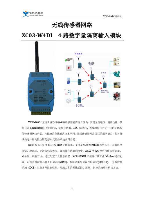
无线传感器网络XC03-W4DI 4路数字量隔离输入模块XC03-W4DI无线传感器网络4路数字量隔离输入模块,实现无线遥控、遥测功能。
模块自带ChipBeeNet自组网协议,是集传感器、I/O、低功耗、无线通信技术于一体的无线智能传感器网络产品。
与传统的有线解决方案不同,无线传感器网络灵活的组网能力,使扩展或构建一种高性价比的分布式监控系统变得容易。
XC03-W4DI采用433/470 MHz无线频率,支持星型/树型/MESH网络拓扑,具有组网灵活,距离远,穿透力强等优点。
在无线传感器网络中,XC03-W4DI模块可作为协调器、路由器、终端节点,通过配置工具任意设置。
XC03-W4DI采用流行的工业Modbus通信协议,可以直接配接各种人机界面屏(HMI)、数据采集与监视控制系统(SCADA)、分散控制系统(DCS)以及各种组态软件,形成完备的无线遥控、遥测、监控系统整体解决方案。
一、 产品特性◆4路IO隔离输入,无线传感器网络组网传输,实现无线遥控、遥测。
◆全工业设计,供电电源、信号输入输出、RS485接口在电气上实现互为隔离,有效抑制工业现场各类串模和共模干扰,保证了工作可靠性和数据精准度。
◆自带ChipBeeNet 无线自组网协议,支持星型/树型/MESH网络拓扑,组网灵活,性能可靠稳定。
◆支持Modbus RTU通信协议,可以直接配接HMI、SCADA、DCS以及各种组态软件。
◆模块内置DC24V 40mA辅助电源,具有短路保护功能,兼容干、湿接点输入。
◆模块在无线网络中可作为协调器、路由器、终端节点,通过配置工具任意设置。
◆数据采集灵活:定时主动上报或上位机查询二、 技术参数开关量输入◆4路有源(湿接点)或无源(干接点)输入◆有源(湿接点)输入时极性自适应◆内置DC24V 40mA辅助电源,具有短路保护功能入◆1500Vdc隔离(可定制为3000Vdc)◆输入电阻:5KOhm◆输入电平:干接点: 逻辑 “0”:接地(GND)逻辑 “1”:开路湿接点: 逻辑 “0”:0 - 2V max逻辑 “1”:4 - 36V通信接口◆物理接口:RS485◆通讯协议:MODBUS RTU:◆波特率:1200、2400、4800、9600、19200、38400、57600、115200 bps◆校验方式:无校验、奇校验、偶校验◆保护功能:防雷、抗干扰设计无线特性◆自主研发的ChipBeeNet无线自组网协议,支持星型/树型/MESH网络拓扑◆无线频率: 433/470频段(出厂前确定中心频率)◆调制方式:2GFSK◆无线信道:20个◆射频数据速率:10Kbps◆最大发射功率:≤100mW(20dBm)◆峰值电流:80mA◆信道检测:CSMA/CA◆接收灵敏度:-117dBm◆网络拓扑:星型/树型/MESH网◆无线通信距离:≤1000米(室外可视,3 dBi天线)◆网络节点容量:最大32个节点(路由节点+终端节点)◆无线距离扩展: 最多5 跳◆节点功能:协调器、路由器、终端设备可任意配置◆天线连接:外置SMA 天线电源输入◆外接电源输入:DC9~36 宽电压输入,具有防反接、防浪涌保护功能◆设备功耗:<3W◆保护功能:防雷、防反接外形结构◆模块结构:亚当模块,10位可拔插端子(2EDG-5.08-10P 弯针)◆安装方式:DIN导轨安装◆外形尺寸: 107.5mm x 72mm x 26mm(不含端子和导轨座)116.5mm x 72mm x 41.5mm(含端子、天线座和导轨座))◆模块重量:约200g环境◆工作温度:-25~+70°C (外接电源)0~+50°C (电池供电)◆工作湿度:20~95%RH(不结露)◆存储环境温度:-20~+85°C◆存储环境湿度:0~95%RH(不结露)三、 外形尺寸和安装示意图图一、模块尺寸图图二、安装示意图四、 安装注意事项1.天线与接收装置的天线尽量保证在同一平面内。
PD30CNG02传感器系列产品说明说明书

Product DescriptionThe PD30CNG02 sensor family comes in a compact 10 x 30 x 20 mm reinforced PMMA/ABS housing. The sensors are useful in applications where detection of transparent objects are needed. Compact housing and high power LED for excellent per-formance-size ratio.The Teach-I n function foradjustment of the sensitivi-ty makes the sensors highly flexible. The output type is preset (NPN or PNP), and the output switching function is programmable (NO or NC).The mute function can be used for testing the sensor for: Malfunctioning, discon-nection, optical axis adjust-ment, dusty and dirty lenses.• Miniature sensor range • Range: 2 m, with reflector• Sensitivity adjustment by Teach-In programming • Modulated, red light 617 nm • Supply voltage: 10 to 30 VDC• Output: 100 mA, NPN or PNP preset• Make and break switching function programmable • LED indication for output, stability and power ON• Protection: reverse polarity, short circuit and transients • Cable and plug versions • Excellent EMC performance •Mute function (sensor blanking)SpecificationsEN 60947-5-2Type SelectionHousing Range Connection Ordering no. Ordering no. W x H x D S nNPNPNPMake or break switching Make or break switching10 x 30 x 20 mm 2 m Cable PD 30 CNG 02 NPMU PD 30 CNG 02 PPMU 10 x 30 x 20 mm 2 m PlugPD 30 CNG 02 NPM5MUPD 30 CNG 02 PPM5MUNote: Reflectors to be ordered separatelyPhotoelectricsRetro-reflective for Transparent Objects Type PD30CNG02....MUPD30CNG02....MUSpecifications (cont.)EN 60947-5-2Wiring DiagramsOperation DiagramPower supply Object Emitted power MuteOFF ONOFF ON Make Output (N.O.)Break Output (N.C.)OFF ON OFFON OFF ON tv = Power ON delayDetection Diagram-150-100-50050100150050010001500200025003000Afstand [mm]B r e d d e [m m ]Excess Gain10100100010000Distance (mm)110100E x c e s s G a i nDelivery Contents• Photoelectric switch: PD 30 CNG 02 ...MU • Installation instruction• Mountingbracket APD30-MB1• Packaging: Cardboard boxSignal Stability IndicationPD30CNG02....MUInstallation HintsAccessoriesDimensionsAccessories• Mounting bracket APD30-MB2 to be purchased separatelyFor make or break set-up (N.O. or N.C.)1. Press the button for 10 seconds, until the green LEDs flashes.2. While the green LED flashes, the output is inverted each time the button is pressed. Yellow LED indicates N.O. function selected.If the button is not pressed within the next 10 seconds, the current output is stored.Teach functionsNormal operation, optimized switching point1. Line up the sensor with the reflector. Yellow LED and Green LED are ON.2. Press the button for 3 seconds until both LEDs flashes simultaneously.(The first switch point is stored)3. Place the object between the sensor and reflector in the detection zone.4. Press the button once and the sensor is ready to operate (Green LED ON, Yellow LED ON) (The second switch point is stored)For maximum sensing distance (default setting)1. Line up the sensor with the reflector, place a new transparant object between the sensor and reflector in the detection zone. Yellow LED is OFF and Green LED is ON.2. Press the button for 3 seconds until both LEDs flashes simultaneously.(The first switch point is stored)3. Press the button a second time and the sensor is ready to operate (Green LED ON, Yellow LED ON) (The second switch point is stored)For the most transparent objects1. Line up the sensor with the reflector. Yellow LED and Green LED are ON.2. Press the button for 3 seconds until both LEDs flashes simultaneously.(The first switch point is stored)3. Press the button a second time and the sensor is ready to operate (Green LED ON, Yellow LED ON)(The second switch point is stored)PD30CNG02....MU10 sec.Push once。
数字光纤传感器FS-V30 31(P) 31C(P) 31M 32(P) 32C(P)说明书

DIGITAL FIBER SENSORFS-V30/31(P)/31C(P)/31M/32(P)/32C(P)Instruction ManualI FS-V31/32/31MI FS-V31P/32P*1 FS-V31/31M only *2 FS-31M only *3 FS-V31P onlyI FS-V31C/32COutput Circuit DiagramInput Circuit DiagramI FS-V31CP/32CPOutput Circuit DiagramInput Circuit DiagramI Socket Cable (Sold Separately)For FS-V31C(P)/32C(P)Pin and wire color table2To dismount the sensor, raise the main body in the direction of the arrow 3 while pushing the both ends of the connected amplifiers in the same way as in step (2).5Sandwich the amplifiers between the end units. Tighten the screws at the top (twoscrews x two units) with a Phillips screwdriver to fix the end units.Move down the fiber lock lever in the direction shown by arrow 4.NoteIf a thin fiber unit is used, an adapter provided with the thin fiber unit will be required.Unless the right adapter is connected, the thin fiber unit will not detect targets correctly. (The adapter is supplied with the fiber unit.)•To connect the coaxial reflective type fiber unit to the amplifier, connect the single-core fiber to the transmitter side, and connect the multiple-core fiber to the receiver side.Pin assignmentPin assignmentOP-73864 (cable length:2 m)OP-73865 (cable length:10 m)with and without a workpiece.12after the calibration is complete. The set value is stored in memory even in that case.I Maximum Sensitivity SettingSet the sensitivity without a workpiece in the case of the reflective type, and with a workpiece in the case of the through-beam or retro-reflective type.Press the SET button for three seconds in the state as shown in the above figure.(Release the button when SET flashes.)When setting the sensitivity, set the value slightly higher than the received light intensity.I Full Auto CalibrationIn this mode, the PV will be set to the mean value of the maximum and minimum incident val-ues obtained within a certain period. Use this mode to detect moving workpieces.1Press the set button for a minimum of three seconds while the target workpiece is passing the sensing area of the fiber unit.•While the SET button is pressed, the sensitivity of the sensor will be set•After the setting is completed, the setting value is displayed on the digital monitor.I Positioning CalibrationFor example, if the target value is set to –10P , the setting value is determined 10% lower than the received light intensity when the SET button is pressed.1When selecting the sensitivity setting method (page 4, No. 2), select the % calibration, and set the target value of calibration.2Taking the desired light intensity as a reference (normally without a workpiece), press the SET button.*While the % calibration is in use, other calibrations (sensitivity setting) cannot be used.*With FS-V31C(P)/32C(P), by periodically performing external calibration from PLC or other devices, stable detection can be performed even with a small sensitivity difference.This function is effective when the light intensity difference is small when judging whether or not there is a workpiece.At Detection mode selection (page 4, No.4), select “Dynamic sensitivity correction mode” beforehand.*How to set the sensitivity is the same as in the normal mode.The DSC indicator illuminates when the DSC function is set.*When Light ON is selected, the upper limit of the correctable range is twice as much as the initial setting value.*The value is stored in memory even after the power is turned off.*The DSC indicator flashes when the light intensity during output OFF greatly fluctuates or the L/D ON selection is inappropriate. In such a case, check the setting again.•When using FS-V31C(P)/32C(P), external inputs can be used.•No inputs are accepted while setting each mode.When external calibration is selected, the operation is the same as with the SET button.I Special FunctionBy performing the following operation, both sensitivity setting and scaling can be performed using external input. Select external calibration (page 4, No. 4-C) and display scaling. The following is the example when using the % calibration.set by pressing the button for 2 seconds or longer.The same steps can be taken to deactivate key lock.For more information on the key lock levels and the PIN number key lock function, refer to page 6.Select “rSt “with the3Select “init” with theDefault settingPower mode:FINEDetection mode: NormalSetting value:50Output selection:L ONI Saving the settings1While pressing, press for 5 seconds or longer.2Select “SAvE” with the3Select “YES” with theI Loading the setting1While pressing , press for 5 seconds or longer.2Select “rSt” with the3Select “[vSt” with thebutton for 3 seconds or longer.Reference。
- 1、下载文档前请自行甄别文档内容的完整性,平台不提供额外的编辑、内容补充、找答案等附加服务。
- 2、"仅部分预览"的文档,不可在线预览部分如存在完整性等问题,可反馈申请退款(可完整预览的文档不适用该条件!)。
- 3、如文档侵犯您的权益,请联系客服反馈,我们会尽快为您处理(人工客服工作时间:9:00-18:30)。
人体存在感应器规格书
X301/X303
人体存在传感器特征:
●无论是运动或静止的人体均能检测;
●人体识别准确度高于85%;
●感应角度80*34度(锥形);
●动态探测距离5米,静态探测距离最
大2米;
●LED工作指示灯
本产品采用超宽谱雷达技术、生物医学工程于一体的感应器,检验人体生命参数是以脉冲形式的微波束照射人体,由于人体生命活动(呼吸、心跳、肠蠕动等)的存在,使得被人体反射后的回波脉冲序列的重复周期发生变化。
对经人体反射后的回波脉冲序列进行解调、积分、放大、滤波等处理并输入微电脑系统进行数据处理和分析,就可以得到与被测人体存在的数据参数。
适合用于学校、酒店、医院、写字楼、展馆、工业等场合或设备进行集中智能控制。
产品命名:
功能介绍:
1、探测是通过Ka雷达波进行人体检测,可对人体位置定位、运动速度判断;X311、
X313均取用人体移动功能及静止检测功能。
2、静态距离为人体与传感器平行时正前方测试的距离;
3、根据不同工作状态,LED灯改变点亮频率;
4、RS485串口或无源开关输出,可接入PC监控,兼容具有RS485的智能控制设
备,人体数据上传;
5、可根据客户要求订制检测区及延时时间。
产品选型:
X311适合用于教室、办公室、楼梯间等非完全静态的地方;
X313适合用于医院、养老院等需长时间静止或动作缓慢的地方;
电气参数
输入电压:DC12V
工作电流:<80mA
感应距离:4米(X301)6米(X303)
感应角度:80*34度
串口模式:RS485
通讯协议:ASCII码
波特率:9600
输出信号:无源开关输出
延时时间:默认30秒(5-1800秒可设置)
(图1)
传感器于人体平行时X301完全静态检测范围<1米;
传感器于人体平行时X303完全静态检测范围<2米。
静态检测距离是根据人体静止时,呼吸肚皮起伏产生的超低频频率检测,若检测距离小于20cm,可根据心跳等频率来检测。
感应角度及方向识别:
(图2)X301 X303产品X轴为80度,Y轴为34度人体静止时主要识别区域
(图3)产品使用说明书
1、打开包装,取出产品
2、接入电源必须按照产品
3、产品物理接口图;
4、产品输出端为Micro US
5、 安装检测无误后通电开产品,根据所选支架正确安装; 照产品要求的额定电压供给; (图4)
ro USB 接口,对应输出功能;
(图5)
通电开始工作,产品面罩上可以看到状态指示灯
指示灯点亮;状态
指示灯长亮时为初始化状态,最长30秒;初始化完成后进入正常感应工作。
6、当检测到有人体移动后,状态(蓝色)指示灯点亮,检测到有效信号后持续
点亮,当有效信号消失后延时约1秒关闭状态指示灯。
7、检测到人体活动后,TTL输出5V高电平(无信号为低电平);输出端口无源
开关C与C’闭合(无信号时是断开状态);若是串口信号通讯时SM=1,(无信号时SM=0);
8、当人离开后,延时一段时间后,无源开关信号断开进入待机状态,待机时状
态信号灯约5秒闪烁一次。
(延时时间可从5-1800秒设置)。
9、调节按钮
调节按键长按指示状态(小于1S秒常亮---1-3秒灯灭---3-6秒灯常亮---6-9秒灯慢闪烁---大于10秒快闪)
【开关状态转换】短按(操作时间小于1S):轻触下按钮改变当前状态(如果当前状态为开,将强制转换为关,不受感应控制;如果当前状态为关,将强制转换为开,不受感应控制)。
如果需要取消强制开/关功能,需断开电源,重新上电也可变为自动感应模式。
【延时时间设置】长按(操作时间在1-3S):长按时间在1-3S进入延时设置状态,进入延时设置状态后,轻触按键调节延时时间。
每次进入调节状态都从“0”开始,每轻触一次加“5”(单位为“秒”);最长可是设置为1800秒,设置超出1800秒等于1800秒。
设置完成后,长按按键5秒(时间到5秒后状态指示灯快闪)退出设置状态或者等待20秒自动退出设置状态。
设置的延时时间断电后不会丢失。
【探测灵敏度设置】长按(操作时间在3-6S):长按时间在3-6S进入灵敏度设置状态,进入灵敏度设置状态后,轻触按键调节灵敏度。
每次进入调节状态都从“0”开始,每轻触一次加“1”;最长可是设置为10,设置超出10秒等于10;“1”为最高灵敏度,“10”为最低灵敏度。
设置完成后,长按按键5秒(时间到5秒后状态指示灯快闪)退出设置状态或者等待20秒自动退出设置状态。
设置的灵敏度断电后不会丢失。
【光照度设置】长按(操作时间在6-9S):长按时间在6-9S进入光照度设置状态,进入光照度设置状态后,轻触按键调节灵敏度。
每次进入调节状态都从“0”开始,每轻触一次加“20”;最长可是设置为2000lux,设置超出2000lux 秒等于2000lux。
设置完成后,长按按键5秒(时间到5秒后状态指示灯快闪)退出设置状态或者等待20秒自动退出设置状态。
设置的光照度断电后不会丢失,需要具备光照感应的产品此功能设置才有效。
【复位重启】长按(操作时间大于10S):长按时间大于10S,所有设置参数将恢复出厂设置,初始化完成后将重新启动。
10、可调通过调节安装的高度及安装角度,控制感应区域的面积,感应面积
计算如下:
11、串口通信模式下,可通过串口设置延时时间、查看延时时间,远程控制
传感器输出,ID读取等功能。
12、使用注意事项
●室内使用;
●请勿安装在通风口及动荡不稳定的物体上;
●减少检测范围内的移动物体,提高人体识别的准确度;
●正确输入稳定的额定电压;
●静止工作在潮湿、高温的环境下;
●严禁拆开外壳触摸探头,触摸之后探头损坏率高达90%。
13、串口通信连接如下:
(图8)
14、串口调试软件
推荐使用sscom.exe串口调试助手
协议格式:ASCII码 默认波特率:9600
16、通讯协议说明
协议传输格式:
1,(协议代码)+(=?)表示读,(协议代码)+(=)+(具体值)表示写。
成功返回“OK”,失败返回“ERROR”。
2,主机每次发送命令为(ID=)+(子机编码)+(空格)+(协议代码(ID除外))+(=)+(具体值或?)+(回车或者空格表示结尾)。
3,命令字符支持为0-9,A-Z,小数点,空格,回车。
字母全部大写。
4,主机特殊命令发送(ID=?)+(回车或者空格),为读子机ID,必须在主机子机一对一的情况下执行,多子机下会出现冲突。
每个产品上都有ID标签,ID为8位数字母和数字,不知道的情况可以通过命令查询ID。
例子:
ID查询模式:
1, 主机发送ID=?
成功后响应子机响应
ID= 1E23DCA0
OK
错误或其他不响应。
ERROR
功能读模式:
2、 主机发送ID=1E23DCA0 SM=?
相应子机收到执行成功后响应
ID=1E23DCA0 SM=1
OK
执行错误响应
ID=1E23DCA0 SM=?
ERROR
功能写模式:
3、 主机发送ID=1E23DCA0 SM=1
相应子机收到执行成功后响应
ID=1E23DCA0 SM=1
OK
执行错误响应
ID=1E23DCA0 SM=?
ERROR
协议代码说明
注:查询地址时,只能1对1
查询。
注:方便后期升级服务
注:人离开后多久关闭输出信号,这个时间的计数倒计时可由CT 查询。
注:。
人体存在状态。
此状态为即时反应,无延时功能,建议小系统或有独立的系统时使用。
一般建议用SM 来作为人体状态检测。
注:当CL值低于IS(N)值,进入人体探测模式,否者待机不工作;
注:通过软件命令重新启动。
若其中部分命令通讯不成功,表示此产品并无此功能;如果您需要此功能的产品,请与我司工作人员联系。
适合用于学校、酒店、医院、写字楼、展馆、工业等场合或设备进行集中智能控制。
更新时间:2018年2月1日
修订版本:REV2.0
1、提高静态检测能力
2、灵敏度通过软件调节。