盈通飞刃计算机主板说明书A970X(A.232)
Cooler Master DA Series 产品说明书

connector
Support
Support
120*1 150*86*140 Fix cable none
8600GT*1 HD3650*1
Dual 29A
none
120*1 150*86*140 Fix cable PCI-E 6pin*1 9600GT*1 HD4850*1
Dual 25A
Active
Dual 28A
Active
80*1 150*86*180 Fix cable PCI-E 6pin*4 GTX260*2 HD4870*2
80*1 80*1
150*86*195
Fix cable
EPS 8pin*2 PCI-E 8pin*3 GTX280*3 PCI-E 6pin*6
HD4870*2 HD4870X2*2
100% modular PCI-E 8pin*1 GTX260*2
150*86*180
cables
PCI-E 6pin*4 GTX280*1
HD4870*2
750W 50℃
Single 60A
Active
120*1
100% modular PCI-E 8pin*1 GTX260*2
150*86*180
Copyright © 2008 SilverStone Technology Co., Ltd. All Rights Reserved
150*86*215
100% modular cables
EPS 8pin*2 PCI-E 8pin*3 PCI-E 6pin*6
GTX280*3
HD4870*2 HD4870X2*2
120*1 150*86*140 Fix cable PCI-E 6pin*1 9600GT*1 HD4850*1
【优质文档】盈通主板cmos设置图解word版本 (1页)
【优质文档】盈通主板cmos设置图解word版本
本文部分内容来自网络整理,本司不为其真实性负责,如有异议或侵权请及时联系,本司将立即删除!
== 本文为word格式,下载后可方便编辑和修改! ==
盈通主板cmos设置图解
虽然盈通主板不是由什么大厂生产的,但是主板的质量稳定,价格也适中,是值得入手的主板。
如下是小编给大家整理的盈通主板cmos设置图解,希望对大家有所作用。
首先将已经使用u大侠u盘启动盘制作工具制作好的u盘插入到电脑主机usb插口(建议将u盘插入到主机箱后置的USB插口处,因为那样传输的性能比
前置的要直接),然后开机!
开启电脑后当看到开机画面的时候,连续按下键盘上的"F11"键(今天小编
用的是201X年之后生产的盈通主板,所以快捷键是F11),如下图所示:为盈
通主板组装的电脑开机的画面。
盈通主板
当我们连续按下快捷热键F11以后将会进入到一个启动项顺序选择的窗口!
如下图所示:进入后的将光标移动到第二选项是“u盘启动”,而第一个
选项则是“电脑本地硬盘启动”。
启动选项
温馨提示:如果默认选项不是u盘,那么请将光标移动到标识的u盘处即
可!今天小编使用的u盘是惠普品牌的!
如上图所示,当把光标移动到u盘选项位置以后,我们可以直接按下回车
键“Enter”即可进入u盘启动!如下图所示:
U大侠
盈通主板组装台式电脑一键U盘启动的热键比较特殊,由年份来划分,
201X年为界,之前的是F8,之后则是F11,大家要先知道自己的主板生产年份,然后就是常规设置,进入了U大侠主菜单了。
盈通bios设置图解教程

盈通bios设置图解教程盈通主板,物美价廉,有较高的性价比。
那么大家知道盈通主板如何设置U盘启动吗?接下来是小编为大家收集的盈通bios设置图解教程,欢迎大家阅读。
盈通bios设置图解教程1、开机时,按F2,进入BIOS菜单。
首先看到的是计算机信息菜单栏,包括计算机型号、BIOS版本,以及CPU、内存、硬盘、光驱等主要硬件信息。
相关信息如下图:2、下图是硬件组态设置。
主要包括:时间、日期设置,无线网卡、硬盘接口模式、显卡、电耗提示音、因特尔虚拟化技术等设置。
相关详细设置如下图(图中把AHCI写成ACHI了,特此更正):3、下图是启动项设置。
系统默认的设置是USB KEY,这就是为什么在插上U盘等移动介质时,计算机无法启动的原因所在。
我们常用的启动项只有几种,一是硬盘启,二是光驱启动,三是U盘量产启动,四是U盘软启动。
我们可以对这些启动项进行相应的调整。
调整方法:把光标移动到所需要调整的项,按数字键后面的“一”键,即可向下移动该选项。
4、下图是小编的重新设置的启动项,其实我们只需把硬盘启动调整到第一项就行了。
在安装系统时,只需要开机按F12,就可以进行首先启动项设置。
5、下图是安全设置,包括超级用户密码和普通用户密码设置,以及启动设置与硬盘密码设置。
相关设置如下图所解。
一般来说,我们只需设置管超级用户密码就行了。
如果硬盘中保存有重要信息,也可以设置硬盘密码。
盈通主板bios设置成中文的方法开机按键进入BIOS设置主界面,因为不同的主板键值是不一样的,可以查看电脑的说明书,或者到品牌机官网查询。
如果是组装机,则看主板的键值。
比如,AMI 3D UEFI BIOS 只要开机按“Delete”或小键盘的“Del”键,即可进入Gigabyte UEFI DualBIOS▶点选菜单栏上的System子菜单(使用向右箭头▶)。
System页面中,“System Language”选项▶此时通常默认English(英文)按一下Enter(回车键),就能弹出“System Language”语言选择菜单,此时默认English(英文)菜单。
AMD Socket AM2(940-pin)处理器 AMD RD780 RX780主板 用户说明书
操作规则:
静电可能严重损害您的设备,在处理主板以及其他的系统设备 的时候要特别注意,避免和主板上的系统组件的不必要接触。保 证在抗静电的环境下工作,避免静电放电而可能对主板造成损 坏,当在您的机箱中插入或者移除设备时,请保证电源处于断开 状态,厂商对于不遵照本操作规则或者不遵守安全规范而对主板 造成的损坏概不负责。
第4章 第5章 第6章 附录:
驱动以及应用程序……………………………………..29 常见问题解答…………………………………………..30 BIOS刷新………………………………………………..33
磐正超磐手主板保修条例………………………………………….. 35
IV
第 1 章 配件
1-1 包装内容
内容 A.主板 B.用户说明书 C.CD D.I/O 挡板 E.SATA II 数据线 F.硬盘数据线 可选设备 G.软驱数据线 H.额外的 USB2.0 扩展端口连接 I. 探温头
3
●USB ·由芯片集成的 USB 控制器提供了 8 个符合 USB2.0 规范的 USB 接口(背部面板提供 4 个接口) ●网卡 ·由板载的 Realtek RTL8111X PCIE 网卡控制器提供 1 个千兆以太网卡 ●S-ATA RAID ·4 个 S-ATA II 接口支持 300MB/S 的带宽,支持 RAID 0,1,0+1 ·1 个 E-SATAII 接口支持 300MB/S 的带宽(可选) ●音效 ·板载的 Realtek ALC8xx 高保真音效解码芯片提供 6 或者 8 声道音效 —支持 CD-IN —支持音频设备安装口智能侦测 —背部面板音频接口配置:根据您所购买的机种,请参考下列表格中的一个 音频接口颜色 2 声道模式 6 声道模式 浅蓝色 线性输入 后置声道输出 草绿色 线性输出 前置声道输出 粉红色 麦克风输入 中置/重低单声道输出 音频接口颜色 浅蓝色 草绿色 粉红色 灰色 黑色 橘色 2 声道模式 线性输入 线性输出 麦克风输入 6 声道模式 线性输入 前置声道输出 麦克风输入 后置声道输出 中置/重低单声道 输出 8 声道模式 线性输入 前置声道输出 麦克风输入 侧边声道输出 后置声道输出 中置/重低单声道输出
映泰主板A970 5.3_BIOS说明书-英文

TA970 UEFI BIOS ManualUEFI BIOS Setup (1)1 Main Menu (3)2 Advanced Menu (4)3 Chipset Menu (16)4 Boot Menu (21)5 Security Menu (23)6 Performance Menu (24)7 Exit Menu (30)iTA970 UEFI BIOS ManualUEFI BIOS SetupIntroductionThe purpose of this manual is to describe the settings in the AMI UEFI BIOS Setup program on this motherboard. The Setup program allows users tomodify the basic system configuration and save these settings to NVRAM.UEFI BIOS determines what a computer can do without accessing programs from a disk. This system controls most of the input and output devices such as keyboard, mouse, serial ports and disk drives. BIOS activates at the first stage of the booting process, loading and executing the operating system.Some additional features, such as virus and password protection or chipset fine-tuning options are also included in UEFI BIOS.The rest of this manual will to guide you through the options and settings in UEFI BIOS Setup.Plug and Play SupportThis AMI UEFI BIOS supports the Plug and Play Version 1.0A specification.EPA Green PC SupportThis AMI UEFI BIOS supports Version 1.03 of the EPA Green PCspecification.ACPI SupportAMI ACPI UEFI BIOS support Version 1.0/2.0 of Advanced Configuration and Power interface specification (ACPI). It provides ASL code for power management and device configuration capabilities as defined in the ACPI specification, developed by Microsoft, Intel and Toshiba.PCI Bus SupportThis AMI UEFI BIOS also supports Version 2.3 of the PCI (PeripheralComponent Interconnect) local bus specification.DRAM SupportDDR3 SDRAM (Double Data Rate III Synchronous DRAM) is supported.1TA970 UEFI BIOS Manual2Supported CPUsThis AMI UEFI BIOS supports the AMD CPU. Using SetupWhen starting up the computer, press <Del>during the Power-On Self-Test (POST) toenter the UEFI BIOS setup utility.In the UEFI BIOS setup utility, you will seeGeneral Help description at the top rightcorner, and this is providing a briefdescription of the selected item. NavigationKeys for that particular menu are at thebottom right corner, and you can use thesekeys to select item and change the settings.NoticeThe default UEFI BIOS settings apply for most conditions to ensureoptimum performance of the motherboard. If the system becomesunstable after changing any settings, please load the default settings to ensure system’s compatibility and stability. Use Load Setup Default under the Exit Menu.For better system performance, the UEFI BIOS firmware is beingcontinuously updated. The UEFI BIOS information described in this manual is for your reference only. The actual UEFI BIOS information and settings on board may be slightly different from this manual.The content of this manual is subject to be changed without notice. Wewill not be responsible for any mistakes found in this user’s manualand any system damage that may be caused by wrong-settings.TA970 UEFI BIOS Manual31 Main MenuOnce you enter AMI UEFI BIOS Setup Utility, the Main Menu will appear onthe screen providing an overview of the basic system information.BIOS InformationIt shows system information including UEFI BIOS version, Project Code, Model Name, Build Date, etc. Total MemoryShows system memory size, VGA shard memory will be excluded. System DateSet the system date. Note that the ‘Day’ automatically changes when you set the date. System TimeSet the system internal clock.TA970 UEFI BIOS Manual42 Advanced MenuThe Advanced Menu allows you to configure the settings of CPU, Super I/O, Power Management, and other system devices.NoticeBeware of that setting inappropriate values in items of this menu may causesystem to malfunction.PCI Subsystem SettingsTA970 UEFI BIOS ManualPCI ROM PriorityIn case of multiple option ROMs (Legacy and EFI Compatible), this item specifies what PCI Option ROM to launchOptions: Legacy ROM (Default) / EFI Compatible ROMPCI Latency TimerThis item sets the value to be programmed into PCI Latency Timer Register. Options: 32 PCI Bus Clocks (Default) / 64 PCI Bus Clocks / 96 PCI Bus Clocks / 128 PCI Bus Clocks / 160 PCI Bus Clocks / 192 PCI Bus Clocks / 224 PCI Bus Clocks / 248 PCI Bus ClocksVGA Palette SnoopThis item enables or disables VGA Palette Registers Snooping.Options: Disabled (Default) / EnabledPCI Express SettingsNo SnoopThis item enables or disables PCI Express Device No Snoop option. Options: Enabled (Default) / DisabledMaximum PayloadThis item sets Maximum Payload of PCI Express Device or allows System BIOS to select the value.Options: Auto (Default) / 128 Bytes / 256 Bytes / 512 Bytes / 1024 Bytes / 2048 Bytes / 4096 Bytes5TA970 UEFI BIOS Manual6Maximum Read RequestThis item sets Maximum Read Request Size of PCI Express Device or allows System BIOS to select the value.Options: Auto (Default) / 128 Bytes / 256 Bytes / 512 Bytes / 1024 Bytes / 2048 Bytes / 4096 BytesASPM SupportThis item sets the ASPM Level: Force LO – Force all links to LO State; Auto – BIOS auto configures; Disabled – Disables ASPM.Options: Disabled (Default) / Auto / Force L0sACPI Settings/WakeUp Event controlEuP ControlWhen EuP is enabled, the system will meet EuP requirement.Options: Disabled (Default) / EnabledACPI Sleep StateThis item selects the highest ACPI sleep state the system will enter when the SUSPEND button is pressed.Options: S1 (CPU Stop Clock) (Default) / Suspend Disabled / S3 (Suspend to RAM)PME Wake up from S5The item enables the system to wake from S5 using PME event.Options: Disabled (Default) / EnabledTA970 UEFI BIOS ManualWake system with Fixed TimeThis item enables or disables the system to wake on by alarm event. When this item is enabled, the system will wake on the hr::min::sec specified. Options: Disabled (Default) / EnabledWake up dateYou can choose which date the system will boot up.Wake up hour / Wake up minute / Wake up secondYou can choose the system boot up time, input hour, minute andsecond to specify.Ring-In Wake up from S5This item enables the system to wake from S5 using Ring-In event. Options: Disabled (Default) / EnabledPS2 Keyboard PowerOnThis item allows you to control the keyboard power on function.Options: Disabled (Default) / Any Key / Stroke Key / Specific Key Stroke Keys SelectedThis item will show only when Keyboard PowerOn is set “Stroke Key.”Options: Wake Key (Default) / Power Key / Ctrl+F1 / Ctrl+F2 / Ctrl+F3 / Ctrl +F4 / Ctrl+F5 / Ctrl+F6Specific Key EnterThis item will show only when Keyboard PowerOn is set “Specific Key.”Press Enter to set Specific key.PS2 Mouse PowerOnThis item allows you to control the mouse power on function.Options: Disabled (Default) / EnabledUSB Device Wakeup from S3/S4This item allows you to enable or disabled the USB resume from S3/S4 function.Options: Disabled (Default) / Enabled7TA970 UEFI BIOS Manual8CPU ConfigurationC1EThis item allows you to configure the Enhanced Halt State (C1E) function, which may reduce the power consumption of your system when the system is idle.Options: Disabled (Default) / EnabledSVMThis item allows you to enable AMD virtualization in CPU. This secure virtual mode will let your run multiple OS (guest) on the same physical hardware by decoupling OS and physical hardware with the hypervisor layer.Options: Enabled (Default) / DisabledPowerNowThis item allows you to enable or disable the generation of ACPI_PPC, _PSS, and _PCT objects.Options: Enabled (Default) / DisabledHTC limitThis item allows you to enable / disable HTC limit.(This item is only for AM3 CPU)Options: Enabled (Default) / DisabledHTC temperature limitThis item allows you to set HTC temperature limit. Range: 70℃ - 95℃ Options: 90 (Default)TA970 UEFI BIOS Manual9Core LevelingThis item allows you to set CPU DowncoringOptions: Auto (Default) / ManualHPC ModeThis item allows you to set High Performance Computing Mode.(This item is only for AM3+ CPU)Options: Disabled (Default) /EnabledCPB ModeThis item allows you to set core performance boost enablement.(This item is only for AM3+ & AM3 revision E CPU)Options: Disabled (Default) /Enabled SATA ConfigurationThe BIOS will automatically detect the presence of SATA devices. There is a sub-menu for each SATA device. Select a device and press <Enter> to enterthe sub-menu for detailed options.OnChip SATA ChannelThis option allows you to enable the on-chip Serial ATA.Options: Enabled (Default) / DisabledTA970 UEFI BIOS Manual10OnChip SATA TypeThis option allows you to select the on-chip Serial ATA operation mode. Options: Native IDE (Default) / RAID / AHCI / Legacy IDESATA IDE Combined ModeThis option controls the SATA/PATA combined mode.Options: Enabled (Default) / DisabledSMART FAN ControlCPU Smart FANThis item allows you to control the CPU Smart Fan function.Options: Disabled (Default) / Auto / 4Pin / 3PinCPU FAN CalibratePress [ENTER] to calibrate CPU FAN.Control ModeThis item provides several operation modes of the fan.Options: Quiet / Aggressive / ManualFan Ctrl OFF(℃)When CPU temperature is lower than this value, the CPU fan will keep lowest RPM.Options: 10 (℃) (Default)Fan Ctrl On(℃)When CPU temperature is higher than this value, the CPU fan controller will turn on.Options: 20 (℃) (Default)TA970 UEFI BIOS Manual11Fan Ctrl Start ValueThis item sets CPU FAN Start Speed Value.Options: 50 (Default)Fan Ctrl SensitiveThe bigger the numeral is, the higher the FAN speed is.Options: 30 (Default)USB ConfigurationLegacy USB SupportThis item determines if the BIOS should provide legacy support for USB devices like the keyboard, mouse, and USB drive. This is a useful feature when using such USB devices with operating systems that do not natively support USB (e.g. Microsoft DOS or Windows NT).Options: Enabled (Default) / Disabled / AutoLegacy USB3.0 SupportThis item enables/disables legacy USB3.0 support.Options: Enabled (Default) / Disabled / AutoEHCI Hand-OffThis is a workaround for OSes without EHCI hand-off support. The EHCI ownership change should be claimed by EHCI driver.Options: Disabled (Default) / EnabledTA970 UEFI BIOS Manual12Super IO ConfigurationRestore AC Power LossThis setting specifies how your system should behave after a power fail or interrupts occurs. Power Off: Leaving the system in power-off status after power recovers. Power ON: Powering on the system immediately when power returns. Last State: 1. Leaving the system in power-off if the system shuts down at DC off status; 2. Powering on the system immediately if the system shuts down at DC on status.Options: Power Off (Default) / Power On / Last State Serial Port 1 ConfigurationTA970 UEFI BIOS Manual13Serial PortThis item enables or disables Serial Port (COM).Options: Enabled (Default) / DisabledChange SettingsThis item selects an optimal setting for Super IO device.Options: Auto (Default) / IO=3F8h; IRQ=4 / IO=3F8h; IRQ=3,4,5,6,7,10,11,12 / IO=2F8h; IRQ=3,4,5,6,7,10,11,12 / IO=3E8h; IRQ=3,4,5,6,7,10,11,12 / IO=2E8h; IRQ=3,4,5,6,7,10,11,12Parallel Port ConfigurationParallel PortThis item enables or disables Parallel Port (LPT/LPTE).Options: Enabled (Default) / DisabledChange SettingsThis item allows you to select an optimal setting for Super IO device.Options: Auto (Default) / IO=378h; IRQ=5 / IO=378h; IRQ=5, 6, 7, 10, 11, 12 / IO=278h; IRQ=5, 6, 7, 10, 11, 12 / IO=3BCh; IRQ=5, 6, 7, 10, 11, 12 / IO=378h / IO=278h / IO=3BChDevice ModeThis item allows you to determine how the parallel port should function. Options: Standard Parallel Port Mode (Default) / EPP Mode / ECP Mode / ECP Mode & EPP ModeTA970 UEFI BIOS Manual CIR Controller ConfigurationCIR ControllerThis item enables or disables CIR Controller.Options: Disabled (Default) / Enabled14TA970 UEFI BIOS Manual15H/W MonitorPWM Processor HotThis item enables/disables PWM Processor Hot.Options: Enabled (Default) / DisabledShutdown TemperatureThis item allows you to set up the CPU shutdown Temperature. Options: Disabled (Default) / 70℃/158℉ / 75℃/167℉ / 80℃/176℉ / 85℃/185℉ / 90℃/194℉TA970 UEFI BIOS Manual163 Chipset MenuThis section describes configuring the PCI bus system. PCI, or Personal Computer Interconnect, is a system which allows I/O devices to operate at speeds nearing the speed of the CPU itself uses when communicating with its own special components.NoticeBeware of that setting inappropriate values in items of this menu may causesystem to malfunction.North BridgeTA970 UEFI BIOS ManualIOMMUThis item allows you to enable/disable NB IOMMU.Options: Disabled (Default) / EnabledNB Port #2/#4/#09/#10Gen2 High Speed ModeOptions: GEN2 Autonomous (Default) / GEN1 / GEN2 Software Initiated / GEN2 Advertize RCPort ASPM supportOptions: Disabled (Default) / L0s enable / L1 enable / L0s + L1 enable / L0s Downstream Only / L0s Downstream Only + L1Link Width (Only for Port #02/#04/#09)Options: Auto (Default) / x1 / x2 / x4 / x8 / x1617TA970 UEFI BIOS Manual18South Bridge ConfigurationSB USB ConfigurationOHCI HC (Bus 0 Dev 18/19/20/22 Fn 0/5)This item allows you to control OHCI host controller. (USB 1.1 Device) Options: Enabled (Default) / DisabledTA970 UEFI BIOS Manual19SB Azalia Audio ConfigurationHD Audio Azalia DeviceThis item allows you to control the HD audio device.Options: Enabled (Default) / Auto / DisabledOnboard DevicesLaunch Storage OpROMThis item enables/disables Boot Option for Legacy Mass Storage Devices with Option ROM.Options: Enabled (Default) / DisabledTA970 UEFI BIOS Manual Realtek PCIE NICThis item enables/disables Realtek PCIE NIC.Options: Enabled (Default) / DisabledOnboard LAN Option ROMThis item enables/disables Onboard LAN Option ROM. Options: Disabled (Default) / EnabledOnboard USB3.0This item enables/disables Onboard USB3.0 Controller. Options: Enabled (Default) / Disabled20TA970 UEFI BIOS Manual214 Boot MenuThis menu allows you to setup the system boot options.Setup Prompt TimeoutThis item sets number of seconds to wait for setup activation key.Options: 2 (Default) Bootup NumLock StateThis item selects the keyboard NumLock state.Options: On (Default) / Off Full LOGO Screen DisplayThis item allows you to enable/disable Full LOGO Screen Show function. Options: Enabled (Default) / Disabled GateA20 ActiveUpon Request – FA20 can be disabled using BIOS services. Always – do not allow disabling GA20; this option is useful when any RT code is executed above 1MBOptions: Upon Request (Default) / AlwaysTA970 UEFI BIOS ManualOption ROM MessagesThis item sets the display mode for option ROM.Options: Force BIOS (Default) / Keep CurrentInterrupt 19 CaptureInterrupt 19 is the software interrupt that handles the boot disk function. When set to Enabled, this item allows the option ROMs to trap interrupt 19. Options: Disabled (Default) / EnabledBIOS Flash protectionWhile enabled, it can’t flash write and flash erase by SMI.Options: Enabled (Default) / DisabledBOOT SUCCESS BEEPWhen this item is set to Enabled, BIOS will let user know boot success with beep.Options: Enabled (Default) / DisabledSmart Multi-CoreThis item sets the smart multi-core. (This item is only for AM3 CPU.) Options: Enabled (Default) / DisabledBoot Option #1/#2/#3The items specify the boot device priority sequence from the available devices. The number of device items that appears on the screen depends on the number of devices installed in the system.CD/DVD ROM Drive BBS PrioritiesThis item sets the order of the legacy devices in this group.Hard Drive BBS PrioritiesThis item sets the order of the legacy devices in this group.22TA970 UEFI BIOS Manual235 Security MenuAdministrator PasswordThis item sets Administrator Password. User PasswordThis item sets User Password.TA970 UEFI BIOS Manual246 Performance MenuThis submenu allows you to change voltage and clock of various devices. (However, we suggest you use the default setting. Changing the voltage and clock improperly may damage the device.)NoticeBeware of that setting inappropriate values in items of this menu maycause system to malfunction.The options and default settings might be different by RAM or CPUmodels.BIO-unlocKINGThis item allows you to activate BIO-unlocKING function.(This item is only for AM3 CPU.)Options: Disabled (Default) / Enabled CPU ClockThis item allows BIOS to select CPU Clock (MHz).Options: 200 (Default) / 200~600 Spread SpectrumThis item allows you to enable or disable spread spectrum forCPU/ATIG/SRC clock.Options: Disabled (Default) / EnabledTA970 UEFI BIOS Manual25Memory Clock ModeThis item allows user to select the DRAM Frequency programming method. If Auto, the DRAM speed will be based on SPDs. If Manual, the DRAM speed specified will be programmed regardless of SPD. If AMP/XMP/XMP2, the DRAM speed specified will be refer memory profile.Options: Auto (Default) / Manual / AMP / XMP1 / XMP2(AMP/XMP is only for AM3+ CPU)Note: The following items appear only when you set the Memory Clock Mode item to [Manual]Memory Frequency: DDR 800 / DDR3 1066 / DDR3 1333 / DDR3 1600 / DDR3 1866AMD Pstate ConfigurationCustom P-StatedThis item will tell BIOS whether to use the step option below this configure the P-State, or whether to configure the P-States automatically.Options: Disabled (Default) / EnabledNote: The following items appear only when you set the Custom P-State item to[Enabled]Core FIDThis item sets the frequency to use for Core P-State selected. Value is saved in the _PSS object.Options: x8 1600MHz ~ x31.5 6300MHzCore VIDThis function allows you to adjust the voltage of CPU Core.TA970 UEFI BIOS Manual26Core DIDThis is the Core Divider.Options: Divided by 1 (Default) / Divided by 2 / Divided by 4 / Divided by 8 / Divided by 16NB FIDThis item sets the frequency to use for Core P-State selected. Value is saved in the _PSS object.Options: 800MHz ~ 6800MHzNB VIDThis function allows you to adjust the voltage of NB Core.HT ConfigurationHT FrequencyThe Hyper Transport link will run at this speed if it is slower than or equal to the system clock and the board is capable.Options: Auto (Default) / 200 MHZ / 400 MHZ / 600 MHZ / 800 MHZ / 1000 MHZ / 1200 MHZ / 1400 MHZ / 1600 MHZ / 1800 MHZ / 2000 MHZ / 2200 MHZ / 2400 MHZ / 2600 MHZ / 2800 MHZ / 3000 MHZ / 3200 MHZ / HT widthThe Hyper Transport link will run at this width.Options: Auto (Default) / 8 BIT / 16 BITTA970 UEFI BIOS Manual27DRAM Timing ConfigurationDRAM Timing ModeThis item selects DRAM Timing Mode.Options: Auto (Default) / DCT0 / DCT1 / BothNote: The following items appear only when you set the DRAM Timing Mode item to [DCT0 / DCT1 / Both]2TCMD Options: Auto (Default) / 1T / 2TCL Options: Auto (Default) / 4~12 CLKTRCD Options: Auto (Default) / 5~12 CLKTRPOptions: Auto (Default) / 5~12 CLKTRASOptions: Auto (Default) / 15~30 CLKTRCOptions: Auto (Default) / 11~42 CLKTWROptions: Auto (Default) / 5~8 / 10 / 12 CLKTWTROptions: Auto (Default) / 4~7 CLKTA970 UEFI BIOS Manual28TRRDOptions: Auto (Default) / 4~7 CLKTRTPOptions: Auto (Default) / 4~7 CLKMCT ConfigurationBank InterleavingThis item allows you to enable or disable Memory Bank interleaving. Options: Auto (Default) / DisabledChannel InterleavingThis item allows you to control the Memory Channel interleaving. Options: Auto (Default) / DisabledMemory Hole RemappingThis item allows you to enable or disable the Memory Remapping Around Memory HoleOptions: Enabled (Default) / DisabledUnganged Mode supportThis item allows you to enable or disable Unganged Mode.Options: Enabled (Default) / DisabledPower Down EnableThis item allows you to enable or disable DDR3 power down mode. Options: Disabled (Default) / EnabledTA970 UEFI BIOS Manual 29Memory Over VoltageThis item allows you to control Memory Over Voltage CPU VcoreThis item allows you to control CPU Vcore. CPU-NB Over VoltageThis item allows you to control CPU-NB Over Voltage.BIOSTAR Memory InsightDDR3_A1/A2/B1/B2These items display SPD information of DDR3 memory.TA970 UEFI BIOS Manual307 Exit MenuThis menu allows you to load the optimal default settings, and save ordiscard the changes to the BIOS items.Discard Changes and ExitAbandon all changes made during the current session and exit setup. Save Changes and ResetReset the system after saving the changes. Restore DefaultsThis selection allows you to reload the BIOS when problem occurs during system booting sequence. These configurations are factory settings optimized for this system. Launch Shell from deviceThis item attempts to EFI Shell application (Shellx64.efi) from one of the available devices.。
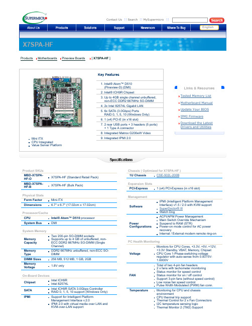
SuperMicro X7SPA-HF Motherboard 产品介绍说明书
English
Links & Resources Tested Memory List Motherboard Manual Update Your BIOS IPMI Firmware Download the Latest Drivers and Utilities
ACPI/APM Power Management Main Switch Override Mechanism Suspend to RAM (STR) Poweron mode control for AC power recovery Internal / External modem remote ringon
OS Compatibility
• Please see our OS Compatibility Chart
LED
Other Features
CPU / System Overheat LED
Chassis intrusion Detection Chassis intrusion Header SDDC Support
Temperature
Monitoring for CPU and chassis environment CPU thermal trip support Thermal Control for 2 x Fan Connectors I2C temperature sensing logic Thermal Monitor 2 (TM2) Support
2. Intel® ICH9R Chipset 3. Up to 4GB single channel unbuffered,
Asus X99-A BIOS说明书
Asus x99 a bios CLICK HERE TO DOWNLOADThe Intel® X99 Express Chipset is a single-chipset design that supports socket LGAv3 Intel® Core™ i7 processors. It provides improved performance by utilizing serial point-to-point links, allowing increased bandwidth and stability. Additionally, X99 provides a maximum 6 USB ports, 10 SATA 6Gbit/s ports for faster data ibacihe.psskazan.rury: Intel-Platform. 产品规格可能随地区或产品批次而有所变动,我们建议您在购买时详细咨询销售商。
产品图片及颜色可能因拍照光线误差及屏幕设定,可能与实物产品效果有所差异,请以实物为准。
. 8 ASUS XE Series BIOS Manual Menu bar The menu bar on top of the screen has the following main items: My Favorites For saving the frequently-used system settings and configuration. Main For changing the basic system configuration Ai Tweaker For changing the overclocking settings Advanced For changing the advanced system settings Monitor For displaying the system temperature, power status. 5/30/ · I cant seem to get into the bios. When I use the asus boot setting utility to go directly into the bios. It restarts my computer and does not display anything. I have 2 graphics cards in the motherboard. I removed the unnecessary peripherals. I tried just the hdmi output for one monitor in the graphics cards and in the motherboard itself. 2/22/ · This is typical ASUS customer service and typical for ASUS software, ASUS software is always buggy and sub-pair of other hardware manufacturers. MSI was very quick with a new BIOS for their X99 boards, the next time i build a new rig it will not be with components from ASUS. ASRock Super Alloy, - XXL Aluminum Alloy Heatsink, - Premium 60A Power Choke, - Premium Memory Alloy Choke, - Ultra Dual-N MOSFET (UDM), - Nichicon 12K Platinum Caps, - Sapphire Black PCB; Supports Intel Core™ i7 and Xeon Core Processors Family for the LGA Socket; Digi Power, 12 Power Phase design; Supports Quad Channel DDR4 +(OC) memory with max. capacity up to . 華碩 xe 系列主板 bios 用戶手冊 5 bios 設置認識 bios 程序華碩全新的 uefi bios 是可延伸固件界面,符合最新的 uefi 架構,這個友善的使用界面,跳脫常規使用鍵盤輸入 bios 方式,提供更有彈性與更便利的鼠標控制操作。
主板用户手册
主板用户手册欢迎使用本品牌主板!本手册将为您提供关于主板的详细介绍和使用指南,帮助您全面了解并正确操作主板。
一、主板简介1. 产品外观请在购买后仔细检查产品外观是否完好,并阅读本手册以了解正确的使用方法和注意事项。
2. 主板特点本主板采用先进的技术和优质的材料,具有以下特点:- 高性能处理器支持:支持最新一代的处理器,提供卓越的计算性能和多任务处理能力。
- 强大的图形性能:支持独立显卡,提供流畅的游戏体验和高清视频播放效果。
- 多功能扩展接口:提供多个PCIe插槽、USB接口、SATA接口等,满足您的各种外设和存储设备需求。
- 稳定可靠的性能:通过严格的质量控制和测试保证了主板的稳定性和可靠性。
二、主板的安装和连接1. 预装主板前的准备- 请确保您已经关闭电源并拔掉电源线。
- 请在安装主板之前将静电释放,以避免静电对主板的损害。
2. 安装主板请按照以下步骤正确安装主板:(1)打开机箱,并找到主板安装位置。
(2)将主板轻轻放入机箱,并确保螺丝孔与机箱对齐。
(3)使用螺丝将主板牢固地固定在机箱上。
3. 连接电源请确保以下电源连接正确无误:- 将电源线插入主板上的电源插口。
- 连接电源线到电源插座上,确保电源稳定。
4. 连接硬件设备请按照以下步骤连接主板和其他硬件设备:(1)连接CPU和散热器:根据散热器的安装说明正确连接散热器到CPU上。
(2)连接内存和扩展卡:将内存插入正确的插槽,然后将扩展卡插入对应的PCIe插槽。
(3)连接存储设备:将硬盘、光驱等存储设备通过SATA接口连接到主板上。
(4)连接其他设备:根据需要,连接键盘、鼠标、显示器等外设。
三、BIOS设置1. 进入BIOS设置请按照以下步骤进入BIOS设置界面:(1)开机后,请按下DEL或F2键进入BIOS设置。
(2)在BIOS设置界面中,您可以通过方向键和回车键进行选项选择和设置。
2. 常用设置在BIOS设置中,您可以进行以下常用设置:- 日期和时间设置:设置当前的日期和时间。
七彩虹 断剑 C.A790GXT Ver1.7 主板 中文说明书
根据中华人民共和国信息产业部发布的《电子信息产品污染控 制管理办法》所展开的 SJ/T11364-2006 标准要求,本产品污染控制标识 以及有毒有害物质或元素标识说明如下:
产品有毒有害物质或元素标识:
产品中有毒有害物质或元素的名称及含量
部件名称
铅(Pb)
汞(Hg)
有毒有害物质或元素
镉(Cd)
六价铬 (Cr(VI))
024—31321755
武汉服务平台
湖北、湖南
027—87865811
南京服务平台
江苏、安徽
025—83611912
上海服务平台
上海、浙江
021—64389499
广州服务平台 广东、广西、福建、海南、江西 020—85276624
成都服务平台 四川、重庆、云南、贵州、西藏 028—85240735
西安服务平台 陕西、甘肃、宁夏、青海、新疆 029—87895086
商标版权
本手册使用的所有商标均属于该商标的持有者所有。 AMD, Athlon , Athlon XP, Thoroughbred 和 Duron™ 是 Advanced Micro Devices 的注册商标。 Intel® 和 Pentium® 是 Intel Corporation 的注册商标。 PS/2 和 OS® 2 是 International Business Machines Corporation 的注册商标。 Windows® 95/98/2000/NT/XP/Vista 是 Microsoft Corporation 的注册商标。 Netware® 是 Novell, Inc 的注册商标。 Award® 是 Phoenix Technologies Ltd 的注册商标。 AMI® 是 American Megatrends Inc 的注册商标。 Kensington 和 MicroSaver 是 Kensington Technology Group 的注册商标。 PCMCIA 和 CardBus 是 Personal Computer Memory Card International Association 的注册商标。 其他在本说明书中使用的产品名称是他们各自所属公司所拥有和被公认的。
梅捷AMD系列主板说明书
梅捷AMD系列主板说明书适用于:AMD系列芯片组说明书版本V1.7更新日期2014年5月30日梅捷简体中文网站/梅捷中国大陆技术支持E-mail:梅捷官方微博/soyo1999梅捷中国大陆服务电话************版权声明:说明书版权归梅捷科技所有。
梅捷科技有权在不知会用户的前提下增益、删除内容。
本说明书为纯技术文档,无任何暗示及映射第三方内容。
且不承担因印刷及排版错误而导致的任何歧义。
本说明书中所涉及之任何第三方之注册商标,所有权归其制造商或品牌供应商所有。
Copyright©1999——2014版权所有、未经授权,禁止以任何方式复制传播。
关于本手册:本说明书适合初学者,包含相关产品特性介绍及软体安装介绍,以及一些名词的解释。
本说明书可以作为技术性参考资料,用户使用时请以实物为准。
非正常保修范围:1、产品因不当使用与安装,自行拆解或更换零件,或是任意变更规格所造成的故障与损坏,不在保修范围内。
2、产品一经变更或修改,以及任何因间接、特殊或意外情况所造成的损害,不在保修范围内。
避免在下列环境中使用本产品:高温、低气压、低温、潮湿、多尘、磁场强大及长期暴露于阳光之下。
本公司建议您在海拔3000米以下,0°至35°C,湿度为5%至95%的环境中使用。
FCC条款:本装置完全遵循FCC条款第15部分的规定。
遵照下列两项条件来作业:1、本装置不会造成人身伤害;2、本装置必须能接受任何已回复的冲突干扰,包括可能会造成不当操作的冲突。
注意:依照FCC条款第15部分规定,本装置已经通过测试并且符合Class B数位装置的限制。
这项限制是为了安装过程中可能造成的伤害性冲突的合理防范措施。
本装置产生、使用、并且可以发射无线电的频率能量,但如果没有依照制造商的指示安装和使用,可能会与通讯工具造成伤害性冲突。
然而,并不保证在特定的安装下不会产生任何冲突。
如果关闭和重开本装置后,仍确定本装置真的造成收音机或电视机的冲突,请使用者利用下列一项或多项知识来更正所造成的冲突:●重新安装接收天线;●增加装置与受讯器间的分隔;●将电脑插入不同的插座以便于两个装置使用不同的回路。
- 1、下载文档前请自行甄别文档内容的完整性,平台不提供额外的编辑、内容补充、找答案等附加服务。
- 2、"仅部分预览"的文档,不可在线预览部分如存在完整性等问题,可反馈申请退款(可完整预览的文档不适用该条件!)。
- 3、如文档侵犯您的权益,请联系客服反馈,我们会尽快为您处理(人工客服工作时间:9:00-18:30)。
特点介绍:
-芯片组: 采用 AMD 970 + SB950 芯片组设计; -CPU 支持: 支持 AMD Socket AM3/AM3+接口处理器; -CPU 频率识别: 自动识别 CPU 主频(免跳线方式) ; -内存支持: 板载 4 条 240 pin DDRIII 内存插槽, 内存容量最高可扩展至 32GB,支持双通道 DDR3 1066/1333/1600/1866MHz(OC) 。
BIOS 设置 ..................................... ………………………………... 5.1 5.2 5.3 5.4 5.5 5.6 5.7 进入 BIOS 主界面 ............................ ………………………. 控制键位 ...................................... …………………………… 主题帮助 ........................................ ………………………….. BIOS 主界面................................. ……....…………………… 高级 BIOS 功能设置....................................... ……………..…. Chipset(芯片组功能设置)....................................………….. C.oclock (超频设置) .............................. …..…………………
清除 CMOS
主板内置 RTC 及 CMOS SRAM。主板上的电池确保 RTC 及 CMOS SRAM 在关机后不会 因为主电源的消失而丢失数据或停止运行。RTC(Real Time Clock 实时钟)的功 能是为 PC 提供正确的时间和日期。系统上所有的设定都储存在 CMOS SRAM 里,每 次开机, CMOS 会自动把设定状态读入系统里。 如果不小心因为设置了 CMOS 信息使 得主机无法正常开机,这时就需要手动清除 CMOS 信息,使其回复原始设置。相关 跳线请见 CLR_CMOS:CMOS 跳线
F_AUDIO 前端音频接口说明:
7
版本:A.232
风扇接口 此处介绍的几个风扇接头在您的安装 过程中扮演着重要的角色。它们是主 板上所有降温风扇的电源供应接头, 提供降低系统及 CPU 温度的重要功能。
在此我们强烈建议您一定要安装散热风扇在 CPU 上,并要将风扇电源线连接 到 CFAN 接头上。
8
A970X Freez F_PANEL 面板插针接口
硬盘动作中指示灯 HDD_LED(Hard Driver LED Header) 将机壳前面板的 HDD LED 指示灯接到此接脚上,便可经由此指示灯看到硬盘运转 的状况。 系统重置按钮 RESET(Reset Control) 将机壳前面板的 RESET 连接线接到此接线,若关闭此开关,则系统将重置并执行 开机自我测试(POST) 。 电源开关按钮接脚 PWR-ON(Power Button) 将机壳前面板上的电源开关电缆连接至此接脚,便可以电源开关按钮打开或者关 闭计算机。 扬声器接脚 +SPEAKER1(Speaker) 透过此扬声器接脚,您可以外接一个扬声器到您的主板上,当计算机开机正常无 误时,此扬声器会发出一短[嘀]声,但若计算机开机时出现不正常状况时,此扬 声器会发出不规则长、短或高的[嘀嘀]声来提醒使用者。 电源指示灯的连接(Power LED) 电源指示灯用来显示主机板的工作状态:亮表示系统处于正常工作状态;灭表示 系统处于软关机状态。
飞刃 A970X
A970X Freez
给用户的说明
本产品的所有部分,包括配件与软件等,其所有权都归本公司所 有,未经本公司许可,不得任意地仿制、拷贝、摘抄或转译。本用户 手册没有任何形式的担保、立场表达或其它暗示。若有任何因本用户 手册或其所提到之产品的所有资讯,所引起直接或间接的信息流失或 事业终止,本公司及其所属员工恕不为其担负任何责任。除此之外, 本用户手册所提到之产品规格及资讯仅供参考,内容亦会随时更新, 恕不另行通知。本用户手册的所有部分,包括硬件及软件,若有任何 错误,本公司没有义务为其担负任何责任。
1
版本:A.232
目
第一章 第二章 第三章 第四章 第五章
录
3 4 6 7 13 13 13 13 14 15 21 21 22 23 24 25
包装说明 .............................. ………………………………………. 综述 ...................................... ………………………………………. 主板位图 ......................................…………………………………. 安装与设置 ...................................... ……………..……………….
内存安装
主板内建 4 条 240-pin 的 DDR3 内存模块扩充槽。必须使用 1.5V 工作电压的内存 模块。安装 240 pin DD3 内存时,请垂直插入插槽中,方向错误会无法完全插入。 请确认方向是否正确,您可以根据内存模块上缺口(指向点)的位置与主板内存 扩充槽的指向点位置确定。两个位置必须对准。 当您安装好 240 pin DDR3 内存时,主板会自动检测 DRAM,并采用正确的电源及存 取时序使内存运行达到最佳状态。
过渡超频可能会导致某些部件的损坏或是使用寿命减少,推荐不要采用超频
方式。
CPU 的安装
:AMD cpu 上的标识应该对应到 CPU 脚座轴的对角位置,请务必注意! 将 CPU ZIF 座的扶手向上扳起 90 度~100 度, 将 CPU 放上 CPU 座, 一只手按住 CPU, 另一只手将 CPU ZIF 座的扶手向下扣住 CPU 座的扣,然后安装 CPU 风扇时请务必 注意风扇的铁扣已扣好,风扇和 CPU 表面接触平整,否则有可能因散热不好导致 CPU 烧毁。 CPU 只有一个方向可以安装到插座中,切记不要用力将 CPU 以错误的方向安装 到插座中!
5.8 Startup (引导选项设置)........ ........... …….………………… 5.9 Security(安全设置).................................. …..………………… 5.10 第六章 Save&Exit(离开 BIOS 设置程序)..........……………………..
驱动安装.....................………………………………………………
附产品质量保证卡
2
A970X Freez
第一章 包装说明
请确认您所购买的主板包装是否完整,如果有包装损坏或是有任何配件短缺的情 形,请尽快与您的经销商联系。 盈通主板一块
ቤተ መጻሕፍቲ ባይዱ
SATA 数据数一根
SATA 电源线/数据线一套
双通道内存的安装
主板支持全新双通道 DDR3 1866/1600/1333/1066 内存模式。主板具有 4 个 DIMM 插槽,每一个代表一个内存通道。 注:使用双通道模式,必须选择容量,频率,品牌相同两根内存同时使用
10
A970X Freez
声音部分连接
Line out 用来连接耳机或喇叭等的音效接收设备,在 8 声道音效输出模式中,这 个接头应该接到前置左右声道(两个主喇叭) ; Line-in 用来连接线性输入设备; Cen/LFE 用来连接中置音箱及重低; SURROUND 用来连接侧面左右声道;Mic 用来 连接麦克风。SUR BACK 用来连接后置左右声道。
CLR_CMOS:清除 CMOS 跳线 如果主板因为 BIOS 设置错误而出现问题,此时可清除 CMOS 解决问题,方法 是:在断开电源的状态下短接 JBAT 1-2 脚 5-6 秒,就可清除 CMOS。请不要在开时 清除 CMOS,否则可能会损坏您的主板。 跳线设定如下表所示: OPEN(缺省设置) Normal Short 清除 CMOS F_USB1/F_USB2/F_USB3 接口说明: 脚位 1/2 3/4 9 信号定义 +5V 电源 D空 脚位 5/6 7/8 10 信号定义 D+ 接地 键位
- ATX架构
第三章 主板位图
5
版本:A.232
(可能和实物有差异,请以实物为准) 第四章 安装与设置
如何辨认跳线的 1 脚位置? 6
A970X Freez 请仔细查看主板,凡有标明“1”或是白色粗线标记的接脚均为 1 脚位置。 JP1 跳线:是否支持键盘开机功能 1-2(缺省设置) 2-3 Disabled (禁用) Enabled (启用)
主板驱动程序光盘一张
主板用户手册一本
I/O 后档板一块
3
版本:A.232
第二章 综述
飞刃 A970X 主板采用 AMD970 + SB950 芯片组设计,全固态电容设计,支持 AMD Socket AM3/AM3+接口处理器, 支持 DDR3 1066/1333/1600/1866(OC)存储架构, 支持新一代 16X PCI EXPRESS 图形接口,板载千兆网卡,板载 8 声道音效,提供 1 个 PCIE 16X 插槽,2 个 PCIE 1X 插槽,2 个 PCI 插槽,性价比极高,是您不可错 过的选择!
本手册所谈论到的产品名称仅做识别之用, 而这些名称可能是属于其他公司 的注册商标或是版权,在此声明如下: IBM,VGA 和 PS/2 属于 International Business Machines 的注册商标。 Intel, Pentium, Pentium Ⅱ, Celeron, Pentium III, Pentium 4 属于 Intel 的注册商标。 Microsoft, MS-DOS, Windows 95/98/NT, Windows2000/XP 等 属 于 Microsoft 的注册商标。 PC-Cillin 和 ChipAway Virus 属于 Trend Micro Inc 的注册商标。 AMI 属于美国 Megatrends Inc 的注册商标。 Award 属于 Award 的注册商标。 MediaRing Talk 属于 MediaRing 的注册商标。 3Deep 属于 E-Color 的注册商标。 本手册中出现的其他商标均已注册。