ePT-100 精确时间测试仪-设备说明书
Series EPT-1 电子压力传感器规格与使用说明书

®WIRINGUse 12 AWG wire maximum for electrical connections and 3/16˝ inner diameter rubber or plastic tubing for pneumatic connections. For your convenience we sell 3/16˝ I.D. rubber tubing, part number A-202, and 3/16˝ I.D. flexible vinyl tubing, part number A-220.See Figures 1 and 2 for wiring configurations and Figures 3 through 5for jumper designations.CAUTION•Ensure that the main supply pressure does not exceed 40 psi (276 kPa).•Ensure a minimum of 6 to 10 feet (1.8 to 3.0 m) of tubing between the transducer and the actuator.•For a 24 VAC supply voltage, ensure that the hot and neutral lines are not reversed. If more than one transducer is being powered from the same power supply, the hot and neutral lines should be the same for each transducer.* Do not connect 120 VAC to the electro-pneumatic transducer.Note:The transducer’s gage is for indication only. The transducer measures more precisely than what is displayed on the gage.WIRING DIAGRAMSFigures 1 and 2 illustrate typical wiring diagrams for the electro-pneumatic transducer.CAUTIONThis transducer contains a half-wave rectifier power supply and must not be powered from transformers powering other devices with non-isolated full-wave rectifier power supplies.ADJUSTMENTS - Jumper ConfigurationThe electro-pneumatic transducer is factory configured for a 4-20 mA input. To change the input, adjust the jumper settings as follows (see figures 3, 4 and 5.)©Copyright 2005Dwyer Instruments, Inc.Printed in U.S.A. 12/05FR# R1-443413-00TRANSDUCER OPERATION•Adjust the input signal to obtain a maximum output pressure for the appropriate range.•Ensure that the output is 15 or 20 psi (100 or 138 kPa).•Adjust the input signal to obtain a minimum output pressure.•Ensure that the output is 3 or 0 psi (20 or 0 kPa).CALIBRATIONAll electro-pneumatic transducers are factory calibrated to meet or exceed published specifications. If field adjustment is necessary, follow these instructions.1.Connect air to the Main port (see figure 6).2.Connect an accurate gage to the Branch port using a minimum of 6 to 10 feet (1.8 to3.0 m) of tubing.3.Connect the (+) and (–) terminals to an appropriate power source. The transducer can accept either a 24 VAC or VDC supply voltage. The maximum supply voltage should not exceed 30 VAC/VDC.4.Apply a low input signal to the (–) and (I) terminals (0 VDC or 4 mA).5.Adjust (Z) to obtain the desired low output pressure.6.Apply a high input signal to the (–) and (l) terminals (5/10 VDC or 20 mA).7.Adjust (S) to obtain the desired high output pressure.8.The zero and span controls are slightly interactive, so steps 4 through 7 should be repeated until the transducer is fully cali-brated.MANUAL OPERATION (select models)To manually control the transducer output, you will need to switch SW up for manual mode (see figure 6). Once in manual mode, you can increase or decrease the output by adjusting PB1 and PB2 (see figure 6).MAINTENANCEAfter final installation of the Series EPT-1 Electro-pneumatic Transducer, no routine maintenance is necessary. A periodic check of calibration is recommended following the procedure listed in the CALIBRATION section. Except for this, these transducers are not field serviceable and should be returned, freight prepaid, if repair is needed.Be sure to include a clear description of the problem plus any application information available. Contact customer service to receive a return goods authorization number before shipping.TRAN S DUCER 18-28 VAC TRAN S FORMER + HOT – NEUTRALCONTROLLER + OUTPUT– COMMON S HIELD/GROUNDLEGEND+ = S UPPLY VOLTAGE – = COMMON = INPUT+–TRAN S DUCER 18-28 VAC POWER S UPPLYCONTROLLER + OUTPUT– COMMON S HIELD/GROUNDLEGEND+ = S UPPLY VOLTAGE – = COMMON = INPUT+–+–MAINBRANCHZ S S W PB1PB2+========S UPPLY VOLTAGE COMMON INPUT ZERO S PANUP (MANUAL) DOWN (AUTO)INCREA S E DECREA S E+–Z S S W PB1PB2Figure 1: Wiring the electro-pneumatic transducer with a 24 VAC supply.Figure 2: Wiring the electro-pneumatic transducer with a 24 VDC supply.Figure 3: Jumper settings for electro-pneumatic transducers with 4-20mA input.Figure 4: Jumper settings for electro-pneumatic transducers with 0-5VDC input.Figure 5: Jumper settings for electro-pneumatic transducers with 0-10VDC input.Figure 6: Terminal locations on the electro-pneumatic transducer.。
卓力特光电仪器(苏州) TST-100 微型数码光弹仪 说明书

TST-100微型数码光弹仪使用说明书卓力特光电仪器(苏州)有限公司TRUST O&E INSTRUMENTS(SUZHOU)CO.,LTD中国· 苏州Suzhou·China目录目 录............................................................I 一前言........................................................1 二光弹仪图解说明............................................2 三模型受力应力分布图....................................... 3 四安装方法....................................................5五注意事项.....................................................5 六TST-100微型数码光弹仪简介.............................6 6.1 TST-100微型数码光弹仪的主要特点..............................6 6.2 主要技术参数及附件...........................................6 6.3 数码光弹仪实验项目...........................................66.3.1 圆盘对径受压实验..........................................7 6.3.2 压弯组合实验..............................................76.3.3 梁的纯弯曲实验............................................7 6.3.4 孔边集中应力实验.........................................8 七光弹性现象..................................................87.1 现象和分析...................................................8 7.2 演示光弹性现象的调试方法.....................................9 八等差线.......................................................98.1等差线现象及分析.............................................9 8.2 整数级的等差线和半数级的等差线...............................9 九等倾线......................................................10 十软件使用说明...............................................11 十一改进补充说明.............................................16十二公司简介..................................................17 封底..............................................................18一前言感谢您选择卓力特光电仪器(苏州)有限公司的TST-100微型数码光弹仪。
EPT使用说明书 V0.1
目录目录 (1)一、安装 (2)1.1系统要求 (2)1.2软件安装 (2)二、运行 (4)2.1关于登录账户 (4)2.2主要区域说明 (5)2.3项目录入 (6)2.4数据复制 (8)2.5对输入的数据核对/检查 (10)2.6从系统库删除 (12)2.7生成图纸 (12)2.7.1指定工作空间 (12)2.7.2生成图纸文件 (13)2.8扩展功能 (14)2.8.1版本转换 (15)2.8.2增加打印标记 (15)2.8.3批量打印 (16)2.9报表控制 (16)三、高级功能自定义图纸简介 (18)3.1基本原则 (18)3.2自定义图纸 (18)3.2.1标题栏各项说明 (19)3.2.2部分“功能代号”注解 (19)3.2.3哑图表格说明 (20)一、安装1.1系统要求 Windows 2000/XPAutoCAD 2007微软 Excel 2000及后续版本可流畅运行以上软件的PC机若干台。
服务器一台(或用其中一台机器为服务器)1.2软件安装本工具的安装程序为“”运行后将出现如下界面如图1-1请认真检查安装版本以确保不会用过时的老版本覆盖了较新的版本;点击下一步后,可看到本工具的功能说明,其中包括主要功能说明、可适用范围和版本更新情况,如图1-2;图1-1继续下一步后,将出现指定安装路径页面,此时请确保所选文件夹为空,以免造成不必要的错误!注:如果所选文件夹为内仍有其它的图纸文件,在生成图纸时有可能会产生不可预知的错误。
点下一步后即开始安装复制过程;之后便完成安装工作。
会在桌面生成图标 。
图1-2图1-3二、运行2.1关于登录账户开始—>程序—>“EPT生产力扩展工具”—> 或双击桌面图标 ,当程序正常运行,首先会弹出用户登录界面,如下图2-1:用以区分不同设计人员制作的图纸。
默认情况下用户名与口令是相同的。
以登录用户“刘轶”为例 :“用户名”输入 ly 按Enter (回车)后输入点自动跳到“口令"处,接着输入密码:ly 按Enter (回车)后就登录了。
百特数显表操作方法之欧阳歌谷创作
百特智能数显表说明书欧阳歌谷(2021.02.01)工作状态下按SET显示LOCY→按SET输入密码18→按SET显示RAN9→按SET通过△▽选择分度号→按SET显示Poin 设置小数点→按SET显示r9.00设置量程下限→按SET显示r9.FS 设置量程上限工作状态下按SET→通过△▽选择COrr按SET显示old.1→按SET通过△▽修正温度值参数设定说明:Locy:菜单上锁操作入口;按SET键确认;按△▽键退出;开锁密码为18Ran9.:分度号和量程设置入口;按SET键确认;按△▽键退出010/…/y:分度号设置;按△▽键设置;按SET确认PoIn:小数点位置设置;按△▽键设置;按SET确认R9.00:量程零点设置;按△▽键设置;按SET确认R9.FS:量程满度设置;按△▽键设置;按SET确认Corr:量程迁移和滤波时间设置菜单入口;按SET键确认;按△▽键取消Old.1:修正温度值;按△▽键设置;按SET确认按键说明:△:变更参数设定时,用于增加数值SET:参数设定确认键▽:变更参数设定时,用于减少数值常见故障处理:仪表通电不亮:供电电源未接入,正确接入仪表电源;接触不良,取出表芯确认弹片接触是否良好。
LED屏显示:broy分度号选择错,选择与输入信号相符的分度号;输入信号太大,调节与输入信号保证在仪表范围内;信号短线,正确接入信号线。
H.oFL.分度号选择错,选择与输入信号相符的分度号;输入信号太大,调节与输入信号保证在仪表范围内;仪表标定错误,选择正确标定信号重新标定。
L.Ofl.:选择与输入信号相符的分度号;输入信号太小,调节与输入信号保证在仪表范围内;仪表标定错误,选择正确标定信号重新标定昌辉SWP系列智能仪表说明书控制方式:1、正确的接线仪表卡入表盘后,请参照仪表随机接线图接妥输入、输入及电源线,并请确认无误。
2、仪表的上电本仪表与电源开关,接入电源即进入工作状态。
3、仪表设备号及版本号的显示仪表在投入电源后,可立即确认仪表设备号及版本号。
Extech BT100 电池容量测试仪用户手册说明书

User ManualBattery Capacity TesterModel BT100Additional User Manual Translations available at IntroductionThank you for selecting the Extech Model BT100. The Battery Tester is designed for measuring the internal resistance and output voltage of batteries including lead storage cells, nickel-cadmium batteries, lithium-ion batteries, and nickel-metal hydride batteries.This device is shipped fully tested and calibrated and, with proper use, will provide years of reliable service. Please visit the Extech Instruments website () to check for the latest version of this User Guide.Features∙Accurate results are achieved using a four-terminal measurement method that eliminates lead and contact resistance.∙1kHz test current with up to 10µΩ resistance resolution.∙Dual display simultaneously indicates the internal resistance and the battery voltage.∙Comparator function with storage of up to 99 sets of resistance and voltage data for battery deterioration characterization.∙Pin type and alligator type 4-terminal Kelvin leads for quick and accurate resistance measurements.∙Memory capacity to store up to 999 (manual datalogging) or 9600 (automatic datalogging) data points.∙Supplied RS232 PC port and Windows compatible software.SafetyInternational Safety SymbolsThis symbol, adjacent to another symbol or terminal, indicates the user must refer to themanual for further information.This symbol, adjacent to a terminal, indicates that, under normal use, hazardous voltagesmay be presentDouble insulationMeter Description1. Power button: Power ON/OFF2. R READ button:① Press R button to start manually loggingreadings.② Press R READ button again to stop logging.3. M MEMORY button:① Under the manual logging mode, the testerstores a single set of logged readings to thememory by pressingM MEMORY button.② Press and hold M MEMORY button for 2seconds to enter continuous (automatic) loggingmode. Press again to stop logging.4. V-RANGE button: Select the voltage range. (4V,40V)5. HOLD button:① Press HOLD to freeze or unfreeze the displayedreading.② Press and hold the HOLD button for 2 secondsthen release, to enter the interval time (samplerate) setting for continuous data logging. Set from1 to 255 seconds. Press Set button to save andexit.6. Ω- RANGE button: Select the resistance range. (40mΩ, 400mΩ, 4Ω, 40Ω)REL button:7.① Press to move the cursor to the right.② Press REL (Relative) to zero the reading.button: Press to increase the displayed value.8.SET button:9.①Press SET to switch the comparator mode on or off.② Press and hold the SET button for 2 seconds to enter the comparator-setting mode. Pressagain to store the setting in memory.10. button: Press to decrease the displayed value.11.① Press to move the cursor to the left.②12. RS-232 connector: PC interface connector.13. – Input jack: Black test lead plug connection.14. + Input jack: Red test lead plug connection.15. LCD display (LED test status indicators are located below the LCD display)16. AC adaptor inputDisplay Description1. Measured resistance reading (or High/Low resistance limit when setting up the comparator)2. Measured voltage reading (or High/Low voltage limit when setting up the comparator)3. The comparator set number (there are 99 sets total)4. The memory location for manually logged data.Symbols:mΩ: Milliohm (resistance)V: VoltageHOLD : Hold function (display freeze)Comparator function enabledLow-BatteryBeeper enabledDATA R : Manual datalogging enabledM : Continuous datalogging enabled (flashes each time data is stored)INTV: Interval time setting for the continuous datalogging function. (1 to 255 seconds) COMP.SET : Comparator settings modeHIGH: High limit setting (threshold) for the comparatorLOW: Low limit setting (threshold) for the comparatorLED Test Status IndicatorsPASS (green LED): Battery is good (within the tolerances of the comparator’s preset limits) WARNING (yellow LED): Battery is beginning to deteriorateFAIL (red LED): Battery has failedThe LED status indications listed above are active when the High/Low comparator limits for internal resistance and the comparator threshold value for voltage are properly configured.OperationPreparation and SafetyThe following safety information must be observed to ensure maximum personal safety during the operation of this tester.∙To avoid electric shock when replacing the batteries: Disconnect the test leads from the device under test before attempting to replace the batteries.∙Check the battery polarity carefully when inserting the batteries. Refer to the battery replacement section (under Maintenance) later in this User Guide.∙Be sure to dispose of used batteries properly.∙Do not attempt to measure DC voltage exceeding 50V.∙Do not attempt to measure AC voltages; this could result in personal injury or damage to the unit.∙To avoid personal injury and/or damage to the unit, do not attempt to measure the voltage of a generator. This will result in an AC voltage being applied tothe voltage generating output terminals.∙After measuring a high voltage battery, and before continuing to measure alow voltage battery, short the measurement leads by touching the lead tipstogether. This will discharge the DC-elimination capacitor (connected acrossthe leads); otherwise a dangerous condition can exist where an excessivevoltage may be applied to the low voltage battery.Test LeadsTwo sets of test leads are supplied with the meter. Both sets provide four (4) terminal Kelvin connections which eliminate lead resistance and probe contact resistance. The application will dictate whether the alligator type or the press-probe type should be used.Testing ProcedureConnect the red test lead to the “+” jack and the black test lead to the “-” jack.1. Press the Power button to switch the tester ON.2. Use the V-RANGE or Ω-RANGE buttons to select the desired Voltage or Resistance range.3. Perform a REL Zero adjustment (see next section) each time the range is changed.4. Connect the red test probe to the positive battery terminal, and the black test probe to thenegative battery terminal.5. Read the battery’s internal resistance and the DC voltage directly on the meter’s display.Note: When the measured DC voltage or battery internal resistance value is over range, “OL” is displayed. When the AC test current faults “- - - -” will be displayed.REL Adjust (ZERO)The REL function zeros the selected range. The reading displayed when the REL button is pressed will be taken as zero and will be used to ‘offset’ subsequent measurements.1. Short the four (4) probe tips of the red and black test leads as shown in the accompanyingdiagrams.2. Press the REL button and the display will show the ‘R’ icon and the resistance and voltagevalues will zero.3. Connect the test leads to the battery to be tested.4. The REL zero adjust must be performed each time the range of the meter is changed, the testleads are swapped, or after switching between resistance and voltage tests.Comparator (99 sets)The comparator function compares the measured values with preset High and Low limit values for internal resistance and threshold voltage level, and determines the range that the measurement should fall into. Then, according to the following conditions, switches ON the corresponding LED, and sounds an audible alert as shown in the table below for the WARNING and FAIL conditions. Comparator Settings1. Press and hold the SET button for 3 seconds then release, the display will showindicating the comparator mode is enabled. 2. Use the or button to change the comparator number from 01 up to 99. 3. Use the V-RANGE or Ω-RANGE buttons to set the desired voltage and resistance measurementrange. 4. Press once, the LOW icon and the left two digits of the low limit resistance will be flashing.(Use the & buttons to select the desired value.) 5. Press once, the right two digits of the low limit resistance will be flashing. (Use theand buttons to select the desired value.) 6. Press once, the HIGH icon and the left two digits of the high limit resistance will be flashing.(Use the and buttons to select the desired value.) 7. Press once, the right two digits of the high limit resistance will be flashing. (Usethe and buttons to select the desired value.) 8. Press once, the left two digits of the threshold voltage will be flashing. (Use theand buttons to select the desired value.)9. Press once, the right two digits of the threshold voltage will be flashing. (Use theand buttons to select the desired value.)10. Repeat step 2 to step 9 to set the next comparator number. 11. Press SET again to exit the comparator setting mode.Comparator Start / Stop Controls1. Press SET to activate the comparator function, the COMP indication will appear on the display. The comparator will operate once measurements are taken.2. Use the and buttons to select the desired comparator number. The selected comparator number remains in memory even when the power is switched off. alert.4. Press SET again to switch off the comparator function.DataloggingManual Data Logging (999 sets)1. Log readings one at a time to the internal memory by pressing the MEMORY button.“DATA M NO XXX” will appear on the LCD for one second to indicate the memory location.2. Press READ button to review logged readings. The display will show “DATA R NO XXX”.3. Use the and buttons to scroll the logged readings.4. Press READ again to discontinue viewing the logged readings.Continuous Data Logging1. Press HOLD for 2 seconds, then release, and the display will show the INTV icon.2. Use the or button to select the desired interval time (datalogging sample rate) from 1second to 255 seconds.3. Press SET to save and exit the interval time setting mode.4. Press and hold MEMORY for 2 seconds to enter the continuous (automatic) logging mode, thedisplay will show the icon.5. The will flash each time a reading is stored.6. Press MEMORY again to exit the continuous datalogging mode.7. Data stored using the continuous datalogging mode cannot be read directly on the tester’sdisplay, it must be downloaded to a PC using the supplied software.Clearing the Datalogger MemoryWhen the internal memory is full, the Full icon will appear on the display and datalogging will stop.1. Press to switch OFF the tester.2. Press and hold the MEMORY button, and while continuing to hold the MEMORY button, pressthe button. The display will show the CLr icon and all datalogged readings will be cleared from memory.SpecificationsResistance measurement method Four (4) terminal Kelvin connectionsA/D conversion Dual slopeDisplays Dual LCD for measurements and programming iconsThree (3) test status LEDsDatalogger Sampling rate 1 to 255 seconds (interval time between logged readings) Open-circuit terminal voltage 3.5Vpp maxMeasurement frequency 1KHz ± 10%Input over range “OL” displayLow battery indication displayTest current fault detect “- - - -” displayAuto power off After approximately 30 minutesZero (Relative) function Circuit offset voltage is displayed as 0VHold function Display freezesAudible Alarm function Audible alert for Warning and Failure conditions (can be setON or OFF)Comparator settings Resistance High/Low limits and Voltage threshold point Number of comparator configurations 99 setsComparator output Test status LEDs for Pass (green), Warning (yellow), and Fail(red) results (audible tone for Warning and Fail conditions)Manual Datalogging memory 999 sets can be stored in meter’s internal memory Continuous (automatic) Datalogging 9600 sets can be stored in meter’s internal memory Operating conditions 0° to 40°C (32 to 104°F)80%RH (non-condensing)Storage conditions -10° to 50°C (14 to 122°F)80%RH (non-condensing)Power source Six (6) ‘AA’ 1.5V batteries; Optional 9V AC adaptor Maximum power consumption 1.0VAMaximum continuous operation 7 hours approx.Altitude 2000m max.Dimensions 250 x 100 x 45mm (9.8 x 3.9 x 1.7”)Weight 500g (1.1 lbs.) approx. (including batteries)Accessories Test Leads and batteriesOptional equipment AC adaptor (9V output)Electrical SpecificationsTo ensure accuracy the ambient temperature should be 23°C ± 5° with a humidity of 80% RH (maximum) non-condensing. In addition, perform a Zero adjustment after each range change.Resistance measurements Temperature coefficient: (±0.1% rdg ± 0.5digits)/°C Measurement frequency: 1KHz ± 10% Measurement burden voltage: 1.5mVACRange Resolution Measurement current Accuracy40m Ω 10µΩ 37.5mA approx.±(1% reading ± 10digits)400m Ω 100µΩ 3.75mA approx.4Ω 1m Ω 375µA approx. 40Ω 10m Ω 37.5µA approx.Voltage MeasurementsTemperature coefficient: (±0.1%rdg ±0.5digits)/ °CRange Resolution Accuracy4V 1mV±(0.1% reading ± 6digits)40V 10mVMaximum Input Voltage: 50VDC maximum No AC voltage input permittedMaximum voltage allowed between input terminals and ground: 60VDC/ACMaintenanceCleaning1. Repair or service not covered in this User Guide should be performed by qualified personnel only.2. Periodically wipe the case with a dry cloth; do not use abrasives or solvents.Battery Check & ReplacementThe symbol will be displayed when the batteries need replacement.1. Disconnect the test leads from the meter and from devices under test2. Switch OFF the power to the tester3. Open the battery compartment cover with a screw driver4. Replace the batteries observing polarity5. Replace and secure the battery coverBattery Safety Reminders∙Please dispose of batteries responsibly; observe local, state, and federal regulations with regard to battery disposal at all times.∙Never dispose of batteries in a fire. Batteries may explode or leak.∙Never mix battery types. Always install new batteries of the same type.As consumers, users are legally required to take used batteries to appropriate collectionsites, the retail store where the batteries were purchased, or wherever batteries are sold.not dispose of this instrument in household waste. The user is obligated to take end‐of‐lifedevices to a designated collection point for the disposal of electrical and electronic equipmentPC SoftwareOverviewThe supplied software combines data acquisition and datalogger functionality.Refer to the Software Help document that comes with the software on how to operate the software.Copyright © 2013‐2016 FLIR Systems, Inc.All rights reserved including the right of reproduction in whole or in part in any formBT100-en-GB_V4.0 11/1611。
ePT-100 仪器(中文)

趋势图
分布图
数据帧
软键盘
仪器界面—交互接口
ABC
123
#+=
1. 仪器结构 2. 仪器界面 3. 仪器维护 4. 仪器功能 5. 仪器应用 6. 演示环境
大纲
工作模式
•串行口 •出厂参数(115200-8-N-1) •1000M-MiniUSB 接口 •100M-DB9接口
仪器维护—诊断
仪器功能—数字示波器
测量信号
•NTP •PTP •GOOSE •SMV
仪器功能—协议捕获分析
文件存储
仪器功能—文件存储与回放
文件回放
仪器功能—文件存储与回放
1. 仪器结构 2. 仪器界面 3. 仪器维护 4. 仪器功能 5. 仪器应用 6. 演示环境
大纲
应用
•时钟源测试和分析 •交换机测试和分析 •智能设备测试和分析
产品特点
•支持时间同步 •时间精度要求高 •输出SMV9-2信息
测试要点
•时钟同步精度 •0秒传输延迟 •采样均匀度(250us) •采样传输偏差(0us) •采样传输速率 •采样同步标志
仪器应用—合并单元测试分析
产品特点
•支持时间同步 •时间精度要求高 •输出GOOSE信息
仪器应用—保护设备测试分析
•合并单元 •保护装置 •智能终端 •测控装置 •…
仪器应用—智能变电站
仪器应用—时钟源测试分析
产品特点
•GPS/BD卫星接入 •时间信号输出 •NTP网络时间信号输出 •PTP网络时间信号输出
测试要点
•北斗/GPS切换抖动测试 •时钟精度(PPS、IRIG-B、NTP、PTP) •同步报文及功能一致性 •PTP时钟同步信号传输机制(t1/t2/t3/t4/修正域) •PTP输出精度、等级及模式一致性(OC/BC/TC、BMC、P2P/E2E) •主备钟切换模式及抖动测试 •检测时钟源输出通道之间的误差( PPS、PTP...) •VLAN验证测试
PT仪使用说明书 2

P-t测试仪使用说明书编制____________校对____________审核____________审定____________批准____________日期____________西安思坦仪器股份有限公司P-t测试仪使用说明书第一版西安思坦仪器股份有限公司目录1概述 (2)2仪器工作原理 (3)3软件使用说明 (4)4仪器维护 (5)P-t 测试仪使用说明书1、概述射孔是一种完井技术,也是增产增效的重要工艺。
为评价射孔效果,需要采集射孔瞬间产生的冲击压力和射孔后的压力恢复数据。
射孔过程持续时间为毫秒级,常规的压力计采集速度较低,无法采集到射孔瞬间的压力数据,只能使用高速压力计——P-t 测试仪。
通过触发快速采样,P-t 测试仪可采集射孔瞬间的压力、加速度和温度信号,也可慢速采集射孔前后的恢复压,为射孔效果评价提供准确详细的资料。
P-t 测试仪由测试和缓冲短节组成,型号为GSYL43-5120C 。
技术指标如下:1)电路部分采 样 速 率:100KHz (压力、加速度、温度) 压力测试精度:0.1%(低速),0.25%(高速) 压力测试范围:0~120MPa 抗冲 击 压力:240MPa 温度测试精度:±0.5℃ 工作温度范围:-20~150℃ 加速测试范围:1250G 抗 冲 击:20000G (0.1ms) 耐 温: 150℃ 功 耗:<70mA (快速),<0.2mA (休眠) 电 池: 9.6Ah (一节)2)结构部分仪器外径 :43mm仪器长度 :测量短节 625mm缓冲短节 472mm连接螺纹 : 1.25”- 16Stub Acme图2仪器结构图1 连接螺纹2、仪器工作原理2.1原理简介该仪器采用高主频耐高温单片机。
其管脚资源丰富,外设接口较多,能实现较复杂的功能。
集成度较高,方便电路设计。
有低功耗模式,满足电池供电的存储式仪器使用需求。
存储器选用并口Flash ,通过数据地址线ADn 和控制线Ctrol进行高速数据的存取,保证高速采样的数据能进行快速保存。
Bosch VET 100 电路分析仪操作说明书
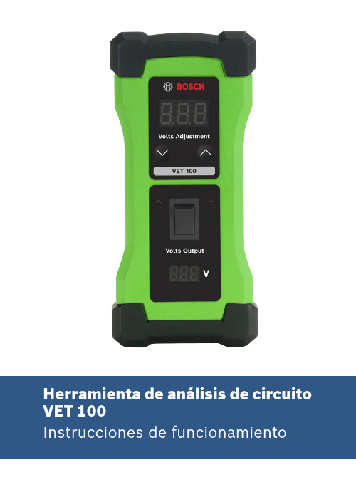
21699501321 | REV. A | Mayo 2019Índice1 Introducción22Advertencias de seguridad 23Componentes de la herramienta 44Pruebas en los sensores defectuosos 55 Pruebas en los sensores con cableado oECM defectuosos 66Teoría del sensor de análisis de circuito 67Consejos técnicos 78 Términos y condiciones de la garantía 81 IntroducciónLa Herramienta de análisis de circuito VET 100 se usa junto a una herramienta de escaneo para diagnóstico a bordo (OBD), como Bosch ADS 625, para identificar los sensores del motor oconjuntos de cables que están defectuosos y los problemas con el módulo de control del motor (ECM).31699501321 | REV. A | Mayo 20192 Advertencias de seguridadExplicación de las palabras de señalización de seguridad Las palabras de señalización de seguridad indican el nivel dePELIGRO: indica una situación de peligro inminente que, si no se evita, podría causar la muerte o lesiones graves.ADVERTENCIA: indica una situación potencialmente peligrosa que, si no se evita, podría causar la muerte o lesiones graves.PRECAUCIÓN: indica una situación potencialmente peligrosa que, si no se evita, podría causar lesiones leves o moderadas.PRECAUCIÓN: si se emplea sin el símbolo de alerta, indica una situación potencialmente peligrosa que, si no se evita, podría causar daños al equipo.PELIGRO: Para evitar lesiones personales graves o la muerte:} Cuando haya un motor en funcionamiento, mantenga la zona de servicio bien ventilada o instale un sistema de extracción de escape en el sistema de escape del motor. Esto evitará la acumulación e inhalación de monóxido de carbono, un gas venenoso inodoro, lo que puede producir lesiones personales graves o la muerte.41699501321 | REV. A | Mayo 2019ADVERTENCIA: Para evitar lesiones personales y/o daños a equipos,} Estudie, asegúrese de comprender y respete todas las precauciones e instrucciones de funcionamiento antes de usar la Herramienta de análisis de circuito VET 100. Si el operador no puede leer estas instrucciones, las precauciones de seguridad y las instrucciones de funcionamiento se deben leer y comentar en el idioma nativo del operador.} No realice conexiones a tierra o de puente entre los cables del sensor y otros circuitos eléctricos del vehículo, a menos que se indique en el manual de servicio del vehículo.} Antes del mantenimiento, asegúrese de que (1) el vehículo se encuentre en estacionamiento (transmisión automática) o neutro (transmisión manual), (2) el freno de emergencia está enganchado y (3) las ruedas están bloqueadas.} Después del mantenimiento del vehículo, reinicie la memoria de códigos por medio de la herramienta de escaneo para OBD.} Mantenga su cuerpo lejos de las correas de transmisión, cables a enchufes de alto voltaje y superficies calientes ubicadas bajo el capó del vehículo.} Use protección ocular que cumpla con las normas ANSI Z87.1, CE EN166, AS/NZS 1337 y OSHA.} Use equipo de protección personal que cumpla con lasnormas ANSI/ISEA y OSHA.51699501321 | REV. A | Mayo 2019} Use la Herramienta de análisis de circuito VET 100 solo en vehículos con sistema de control del motor computarizado.} No use la Herramienta de análisis de circuito VET 100 para ningún otro propósito que no sea su objetivo previsto.} No altere esta herramienta.} Inspeccione el estado de la Herramienta de análisis de circuito VET 100 antes de cada uso; no la utilice si está dañada, alterada o en malas condiciones.} Reemplace una Herramienta de análisis de circuito VET 100 dañada usando solo los componentes de repuesto que aparecen en la sección 3 de las instrucciones de funcionamiento.} Consulte el manual de servicio del vehículo al que se le harán trabajos de servicio. Siga todos los procedimientos diagnósticos y las precauciones. De lo contrario, podrían producirse lesiones personales o reparaciones innecesarias.61699501321 | REV. A | Mayo 20193Componentes de la herramienta12345671699501321 | REV. A | Mayo 20194Pruebas en los sensores defectuosos 1.Apague el encendido del vehículo antes de desconectar cualquiera de los sensores del motor.2. Conecte la Herramienta de análisis de circuito VET 100 a la batería del vehículo usando las pinzas positiva y negativa. Consulte la figura 1. NOTA: El voltaje de la batería aparece en la parte inferior de la Herramienta de análisis de circuito VET 100.3. Consulte los diagramas de cableado eléctrico del vehículo para determinar qué cable de señal del sensor sondeará con voltaje. Consulte el manual de servicio del vehículo para conocer el voltaje de operación correcto del sensor que está probando.4. Configure el voltaje de la Herramienta de análisis de circuitode 0,5 V a 7 V y se puede ajustar en incrementos de 0,5 V.5. Aplique voltaje al cable de señal del sensor que corresponda al tocar la sonda de prueba positiva (roja) y presionar el interruptor de encendido en la Herramienta de análisis de circuito VET 100.6.Lea la herramienta de escaneo para OBD (no incluida con la Herramienta de análisis de circuito VET 100) para ver si la lectura muestra el mismo voltaje que aplicó la Herramienta de análisis de circuito VET 100. Si la lectura de voltaje es inferior a lo que se aplicó, el conjunto de cables o ECM tiene una posible pérdida de voltaje y podría requerir reparación o reemplazo. Si el voltaje es igual al que se aplicó, el sensor está defectuoso y se debe reemplazar. NOTA: La señal de voltaje puede traducirse a una lectura de presión o temperatura.81699501321 | REV. A | Mayo 2019Figura 15 Pruebas en los sensores con cableadoo ECM defectuosos1. Si realizó los pasos de la sección 4, “Pruebas en los sensoresdefectuosos”, vuelva a conectar todos los sensores al motor antes de encender el vehículo.2. Conecte la Herramienta de análisis de circuito VET 100 a labatería del vehículo usando las pinzas positiva y negativa.Consulte la figura 1. NOTA: El voltaje de la batería aparece en la parte inferior de la Herramienta de análisis de circuito VET 100.3. Consulte los diagramas de cableado eléctrico del vehículopara determinar qué cable de señal del sensor sondearácon voltaje. Consulte el manual de servicio del vehículo para conocer el voltaje de operación correcto para el cable deseñal del sensor que está probando.4. Configure el voltaje de la Herramienta de análisis de circuitode circuito VET 100 es de 0,5 V a 7 V y se puede ajustar enincrementos de 0,5 V.91699501321 | REV. A | Mayo 20195. Aplique voltaje a la aguja de ECM del cable de señal del sensor que corresponda al tocar la sonda de prueba positiva (roja) directo en la aguja y presionar el interruptor de encendido en la Herramienta de análisis de circuito VET 100.6.Lea la herramienta de escaneo para OBD (no incluida con la Herramienta de análisis de circuito VET 100) para ver si la lectura muestra el mismo voltaje que aplicó la Herramienta de análisis de circuito VET 100. Si la lectura de voltaje es igual a lo que se aplicó, el conjunto de cables está defectuoso. Si la lectura de voltaje es inferior a lo que se aplicó, el ECM no está procesando adecuadamente la señal de voltaje y podría requerir reemplazo. NOTA: La señal de voltaje puede traducirse a una lectura de presión o temperatura.6 Teoría del sensor de análisis de circuitoSensores controlados por computadora:Los sensores están diseñados para monitorear diversas condiciones que podrían afectar el desempeño de un vehículo. El ECM utiliza estas señales para controlar la mezcla de combustible, tiempo de encendido, velocidad de ralentí, válvula de recirculación de gases de escape (EGR), válvula de purga y otras funciones relacionadas con las emisiones. La falla de cualquiera de los sensores del ECM puede producir una serie de problemas en la capacidad de conducción, incluyendo sin limitación: arranque difícil, ralentí irregular, falla intermitente, detención, velocidad de ralentí excesiva, emisiones excesivas del tubo de escape o cambio de marcha incorrecto. La Herramienta de análisis de circuito VET 100 puede aplicar voltaje tanto a los sensores como al ECM, lo que permite al usuario determinar si los sensores están funcionando adecuadamente y si el ECM recibe correctamente la señal del sensor.Los sensores controlados por computadora se dividen en dos categorías. Consulte la página siguiente.101699501321 | REV. A | Mayo 20191. Sensores de resistencia variable Estos tipos de sensores también se denominan sensores “de dos cables”. Normalmente tienen dos cables que se conectan al ECM, un cable de suministro de voltaje y un cable de retorno de señal. Estos sensores incluyen: sensores de temperatura del refrigerante, sensores de temperatura del aire del colector y sensores de temperatura del aire exterior. Consulte la figura 2.2. Sensores de voltaje variable Estos tipos de sensores también se denominan sensores “de tres cables”. Normalmente tienen tres cables que se conectan al ECM, un cable de suministro de voltaje, un cable de retorno de señal y un cable de conexión a tierra. Estos sensores incluyen: sensores de posición del acelerador, sensor de presión absoluta del colector (MAP), sensor de presión barométrica y algunos sensores de masa de flujo de aire. Consulte la Figura3.Figura 2Figura 3 Motor SensorsalidaEntrada de datosComputadoraSalida de señal(voltaje variable)111699501321 | REV. A | Mayo 20197 Consejos técnicos} El voltaje máximo de la Herramienta de análisis de circuito es de 7 V y se diseñó para ajustarse en forma segura al rango operativo de la mayoría de los ECM.} Para calcular la resistencia del voltaje, use la Ley de Ohm (R = V/I), donde la resistencia (R) en ohms es equivalente al voltaje (V) en voltios divido por la corriente (I) en amperes. Si el voltaje back-end recibido por el ECM es inferior al voltaje front-end emitido por la Herramienta de análisis de circuito, hay una caída de voltaje. Esta caída de voltaje indica que existe corrosión en el sensor o en el conjunto de cables, lo que provoca que llegue un voltaje inferior a lo normal al ECM.} Consulte el diagrama de cableado para confirmar el voltaje correcto en los sensores.} Conecte la Herramienta de análisis de circuito solo a sistemas de batería de 12 o 24 V. Si el voltaje de la batería es bajo, aparecerá una luz roja parpadeando en la interfaz de usuario.} Use esta herramienta en conjunto con una herramienta de escaneo para OBD con el propósito de identificar la causa del código de falla y reparar los problemas que generan códigos de falla en los componentes del vehículo, incluyendo sin limitación: voltaje del pedal del acelerador hasta 5 V, voltaje de señal EGR hasta 5 V, válvula reguladora de diésel, conjuntos de acelerador, sensores del árbol de levas, sensores del cigüeñal, sensores de masa de flujo de aire (MAF), sensores de MAP, sensores de estacionamiento, sensores de temperatura, sensores de presión de aceite y componentes basados en transductores.121699501321 | REV. A | Mayo 20198 Términos y condiciones de la garantía Esta garantía se limita expresamente a los compradores minoristas originales de herramientas de diagnóstico electrónicas Bosch nuevas o reacondicionadas (“unidades”).• Las unidades Bosch nuevas tienen garantía por defectos en los materiales y en la fabricación durante un año (12 meses) a partir de la fecha de entrega.• Los cables y accesorios tienen garantía por defectos en los materiales y en la fabricación durante 90 días (3 meses) a partir de la fecha de entrega.Esta garantía no cubre ninguna unidad que haya sido maltratada, alterada, usada con un fin distinto al previsto o usada de una manera no coherente con las instrucciones de funcionamiento. La única y exclusiva compensación por cualquier unidad que se determine como defectuosa es la reparación o el reemplazo, a criterio de Bosch. En ningún caso Bosch será responsable por daños directos, indirectos, especiales, imprevistos o emergentes (incluyendo la pérdida de ingresos), ya sea por garantía, contrato, agravio o cualquier otra base legal. La existencia de un defecto será determinada por Bosch de acuerdo con procedimientos establecidos por Bosch. Nadie tiene autorización para hacer ningún enunciado o declaración que altere los términos de esta garantía.Exención de responsabilidad La garantía anterior reemplaza a cualquier otra garantía, expresa o implícita, incluyendo garantías de comerciabilidad o adecuación para un propósito específico.Servicio técnico Si tiene preguntas sobre el funcionamiento del producto, llame al 855-267-2483 o visite .Bosch Automotive Service Solutions Inc. 655 Eisenhower Drive • Owatonna, MN 55060 USA。
- 1、下载文档前请自行甄别文档内容的完整性,平台不提供额外的编辑、内容补充、找答案等附加服务。
- 2、"仅部分预览"的文档,不可在线预览部分如存在完整性等问题,可反馈申请退款(可完整预览的文档不适用该条件!)。
- 3、如文档侵犯您的权益,请联系客服反馈,我们会尽快为您处理(人工客服工作时间:9:00-18:30)。
上海远景数字信息技术有限公司
精确时间测试仪 ePT-100
目录
1. 基本信息 ............................................................................................................... 3 1.1. 简介 ......................................................................................................... 3 1.2. 特征 ......................................................................................................... 5 1.2.1. 时间基准 .......................................................................................... 5 1.2.2. 测量和测试功能 ............................................................................... 6 1.2.3. 时间信号输入................................................................................... 9 1.2.4. 数据分析显示................................................................................. 10 1.2.5. PTP 功能......................................................................................... 11 1.2.6. NTP 功能........................................................................................ 12 1.2.7. IEC61850 SMV 模拟输出功能....................................................... 12 1.2.8. IEC61850 GOOSE 模拟输出功能 .................................................. 12 1.2.9. IEC61850 GOOSE 订阅功能.......................................................... 12 1.2.10. 串行 TOD 模拟输出功能 ........................................................ 12 1.2.11. 以太网报文捕捉和分析功能................................................... 13 1.2.12. 时间信号输出 .......................................................................... 13 1.2.13. 设置和操作配置 ...................................................................... 14 1.2.14. 数字示波器功能 ...................................................................... 14 1.2.15. NAND flash 或 USB 盘存储.................................................... 15
-2-
上海远景数字信息技术有限公司
1.
1.1. 简介
精确时间测试仪 ePT-100
基本信息
ePT-100 精确时间测试仪(以下简称 ePT-100 测试仪)是一款便携式时间测试 仪,专门用来测试各类时间信号及时间系统。其主要特点包括时间信号/时间报 文的模拟输出,信号输入测量,测试结果分析统计。ePT-100 是专门用来帮助时 间同步技术的开发,特别是 IEEE1588 及 IEC61850 设备和系统。
ePT-100 测试仪支持高精度测量基准时钟,可以与 GPS、Galileo、BD-Star 等绝 对时钟系统同步,也可以通过外部扩展接口与本地时钟源(外部 GPS、IRIG-B 等 信号)同步。这一设计使 ePT-100 测试仪用来测试绝对时间(绝对时间的基准) 或相对时间(相对时间的基准)。
ePT-100 测试仪能够监测、捕获、存储、分析时钟脉冲。可以根据基准时钟测试 多路 PPS(秒脉冲数)、PPM(分钟脉冲数),并能根据高精度的基准时钟测量 输入误差。
ePT-100 精确时间测试仪
说明书
eCon Technologies Inc 版权所有 R3.50
上海远景数字信息技术有限公司 上海市浦东新区新金桥路 1295 号 2 号楼 5楼 电话:+86-21-6162-9201 传真:+86-21-6162-6213 E-mail:dgmarket@
-1-
Байду номын сангаас
上海远景数字信息技术有限公司
精确时间测试仪 ePT-100
2.17. 外部同步接口描述 ................................................................................ 23
2.18. OCXO.................................................................................................... 23 2.19. 铷原子钟 ............................................................................................... 24 2.20. 彩色触摸屏 ........................................................................................... 24 2.21. 维护口 ................................................................................................... 24 2.22. 电源 ....................................................................................................... 25 2.23. 环境 ....................................................................................................... 25 表格索引.................................................................................................................... 26
ePT-100 测试仪能够用来测量、捕获、存储、分析时钟信息。这些时钟信息包括 PTP、NTP、IRIG-B、串行(EIA-232 或 EIA-422)时钟信息、NTP 及 PTP。其中 PTP 测试,可以测试 OC、BC、TC 的测试,NTP 支持 NTP Server 和 Client 功 能。
2. 系统参数及接口说明 .......................................................................................... 16 2.1. 测量参数说明内存描述 ........................................................................ 16 2.2. 测量内存描述........................................................................................ 16 2.3. 信号输入接口描述 ................................................................................ 17 2.4. 数字示波器参数描述 ............................................................................ 18 2.5. 以太网 ................................................................................................... 19 2.6. 数据存储描述........................................................................................ 19 2.7. 内部同步时间源描述 ............................................................................ 19 2.8. PTP 协议............................................................................................... 20 2.9. NTP 协议 .............................................................................................. 20