USB系列规格书
USB摄像头需求规格书0.2

广电云-IP智能机顶盒配件USB摄像头需求规格书
1.产品规格
2.应用场景
2.1USB摄像头配件通过USB口与机顶盒连接:
机顶盒正常开机后,配件通过USB口与机顶盒连接,机顶盒通过USB口与配件通信并进行供电,要求即插即用,能够自动连接,提供视频和语音服务,见图2.1,具体实现方式请配件厂商提供一份概要设计方案以供讨论。
此方案中,机顶盒安装apk后,显示对端手机(或机顶盒)的语音和图像,USB摄像头采集本地语音和图像输入,和对端的手机(或机顶盒)进行视频通话。
图1组合模式
2.2 USB摄像头通过WIFI与机顶盒连接:
机顶盒正常开机后,配件距离机顶盒较远位置时,则配件自行配置电源适配器供电运行,USB摄像头作为一个WIFI终端设备,与机顶盒连接,提供视频和语音服务,见图具体实现
方式请配件厂商提供一份概要设计方案以供讨论。
此方案中,
监控模式:机顶盒安装apk后,显示usb摄像头采集的语音和图像,对摄像头区域进行监控。
图2监控模式
独立模式:独立使用USB 摄像头和远程手机(或机顶盒)进行通话或监控,机顶盒只提供网络接入功能。
图3独立模式。
32AWG USB 3.1 线材规格书资料
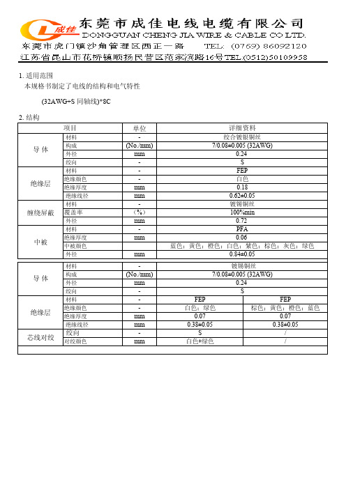
1. 适用范围本规格书制定了电线的结构和电气特性(32AWG+S 同轴线)*8C2. 结构单位-(No./mm)mm ---mm mm -(%)mm -mm mm -(No./mm)mm ---mm mm -mm中被颜色蓝色;黄色;橙色;白色;紫色;棕色;灰色;绿色FEP FEP0.070.38±0.05白色*绿色S //绞向对绞颜色芯线对绞绝缘层材料绝缘颜色绝缘厚度 绝缘线径导 体材料 镀锡铜丝构成7/0.08±0.005 (32AWG)外径0.24 绞向S缠绕屏蔽 外径0.84±0.05覆盖率外径0.06材料PFA 中被绝缘厚度绝缘层材料绝缘厚度 绝缘线径绝缘颜色0.62±0.05镀锡铜丝100%min 0.72白色;绿色0.070.38±0.05棕色;黄色;橙色;蓝色S FEP 0.18 材料白色项目详细资料材料导 体构成 绞向 外径绞合镀银铜丝7/0.08±0.005 (32AWG)0.24单位Ω/km M Ω·km V/ 1 Min ΩΩ ps/m4. 电线截面图示如下:颜色代码1.蓝色;2.黄色;3.橙色;4.白色;5.紫色;6.棕色;7.灰色;8.绿色9.棕色;10.黄色;11.橙色;12.蓝色13.白色;14.绿色;15.红色SKEW≥10绝缘电阻 耐压强度项目导体电阻详细资料32AWG:613(Max.) 24AWG:94100(Min.)1000 特性阻抗45±3差分阻抗90±3761813109543215141211。
SL2.2S规格书,usb HUB大全,替换FE1.1S,GL850,GL852,PL2586
USB2.0 HUB控制器集成电路USB 2.0 HIGH SPEED 4-PORT HUB CONTROLLERSL2.2s数据手册Data Sheet内容目录第一章管脚分配 (3)1.1 SL2.2S管脚图 (3)1.2 SL2.2S管脚定义 (3)第二章 功能叙述 (5)2.1综述 (5)2.2指示灯 (5)2.2.1单灯方案 (5)2.2.2多灯方案 (6)2.2.3 LED指示定义 (6)2.3过流保护 (6)2.4充电支持 (6)2.5I2C接口 (7)2.6EEPROM设置 (7)第三章电气特性 (8)3.1极限工作条件 (8)3.2工作范围 (8)3.3直流电特性 (8)3.4HS/FS/LS电气特性 (8)3.5ESD特性 (8)附录一封装 (9)表格目录表格1: 端口LED定义 (6)表格 2 : ACTIVE LED定义 (6)表格3:EEPROM数据结构定义 (7)表格4: 最大额定值 (8)表格5: 工作范围 (8)表格6: 直流电特性 (8)插图目录图1:SSOP28 管脚图 (3)图2:单灯方案配置 (5)图3: 5灯方案配置 ............................................................................... (6)图 4:附录 封装图 ................................................................................... .9第一章管脚分配1.1SL2.2s管脚图图1:SSOP28 管脚图1.2SL2.2s管脚定义管脚名称28Die IO类型定义Pin#VSS 1 P 芯片地XOUT 2 O晶振PAD XIN 3 IDM4 4 B下行口4的USB信号DP4 5 BDM3 6 B下行口3的USB信号DP3 7 BDM2 8 B下行口2的USB信号DP2 9 BDM1 10 B下行口1的USB信号DP1 11 BVDD18 12 P 模拟1.8vVDD33 13 P 模拟3.3v - 14 NCUDM 15 B上行口的USB信号UDP 16 BRESET_N 17 I,Pu 芯片外部复位输入- 18 NCPSELF 19 I,Pu 高为自供电,低为总线供电VDD5 20 P 5v输入VDD33 21 P 3.3v输出DRV 22 B,Pu 点灯驱动信号LED1 23 B,Pu 点灯驱动信号LED2 24 B,Pu 点灯驱动信号PWRN 25 B,Pu 下行口电源输出控制,低有效OVCRN/SDA 26 B,PuI2C SDA数据线,内部上拉;芯片初始化完成后作为过流保护输入脚,低有效SCL 27 B,Pu I2C SCL时钟输出VDD18 28 P 数字1.8v注释:O,输出;I 输入;B 双向;P 电源/接地;Pu 上拉;Pd 下拉;NC 悬空;第二章 功能叙述2.1综述SL2.2s 是一颗高集成度,高性能,低功耗的USB2.0集线器主控芯片;该芯片采用STT 技术,单电源供电方式,芯片供电电压为5v , 内部集成5V 转3.3V,只需在外部电源添加滤波电容;芯片自带复位电路,低功耗技术让他更加出众。
MICRO_USB_母座规格书

目录表承认书封面目录表产品图面(第1页)产品包装规范(第2页)产品规格书(第3~7页)产品检验报告(第8页)群组测试报告(第9~11页)电镀及盐雾测试报告(第12~14页) 黃卡(第15页)材质证明(第16~20页)SGS报告(第21~23页)承认书封底科宇塑胶五金有限公司ѻ ẔFIRST ARTICLE INSPECTION REPORT科宇塑胶五金有限公司PAGE 1/3Keyu Plastic Hardware CO.,LTDFILE NAME: QUALIFICATION TEST REPORTPART NAME:MICRO USB CONNECTORPART NOMBER:C-1105-2100-21272/C-1105-2101-21272DATE:2007-06-041. INTRODUCTION1.1. PurposeTesting was performed on the MICRO USB connector to determine its conformance tothe requirements of Product Specification SPEC-0001 Rev A01.2. ScopeThis report covers the electrical, mechanical, and environmental performance ofMICRO USB manufactured by the Assembly Division.1.3. ConclusionMICRO USB connector meets the electrical, mechanical, and environmentalperformance requirements of Product Specification SPEC-0001 Rev A0.1.4. Product Description see specification1.5. Test SamplesThe test samples were randomly selected from normal current production lots, and thefollowing part numbers were used for test:Test Group Quantity Description1, 2,3,4,5, 5 pcs MICRO USB1.6 QUALIFICATION TEST SEQUENCE SEE SPECIFICATION SPEC-0001PAGE 2/3 1.7 TEST DATADATA NO.TEST SPEC. UNIT Mean Ӻ Max. Min. AppearanceNo Damage 5 conn OK OK OK Contact ResistanceMax 30m Ө 25 cont. 24.52 5.20 26.20 21.00 Connector Mating ForceMax 35N 5 conn 13.04 1.30 13.90 12.60 Connector Unmating Force8̚20N 5 conn. 18.80 2.30 19.00 16.70 Durability10000 Cycles 5 conn OK OK OK Connector Mating ForceMax 35N 5 conn 9.34 1.5 10.00 8.50 Connector Unmating Force8̚20N 5 conn 10.56 0.8 11.20 10.60 Contact ResistanceMax: 40m Ө 25 cont. 27.34 7.06 32.06 25.00 1 AppearanceNo Damage 5 conn. OK - OK OK AppearanceNo Damage 5 conn OK OK OK Contact ResistanceMax 30m Ө 25 cont. 24.23 4.52 26.82 22.30 Connector Mating ForceMax 35N 5 conn 12.82 0.70 13.20 12.50 Connector Unmating Force8̚20N 5 conn. 16.64 0.6 17.00 16.40 Random Vibration1 µ s Max 5 conn OK - OK OK Physical Shock1 µ s Max 5 conn OK OK OK Connector Mating ForceMax 35N 5 conn 12.76 0.36 13.00 12.64 Connector Unmating Force8̚20N 5 conn 16.52 0.27 16.90 16.36 Contact ResistanceMax: 40m Ө 25 cont. 27.84 6.90 31.50 24.60 2 AppearanceNo Damage 5 conn. OK - OK OK AppearanceNo Damage 25 cont.. OK - OK OK Insulation ResistanceMin:100Ө 25 cont. OK - OK OK Dielectric Withstanding Voltage100 VAC 1 minute 25 cont. OK - OK OK Thermal Shock-55к~85к 5cycles 5 conn. OK - OK OK Humidity25к~65к95%RH 7cycles(168Hour) 5 conn. OK - OK OK Insulation ResistanceMin:100Ө 25 cont. OK - OK OK 3 Dielectric Withstanding Voltage 100 VAC 1 minute 25 cont. OK - OK OK科宇塑胶五金有限公司Keyu Plastic Hardware CO.,LTDPAGE 3/31.8. TEST RESULTPASS科宇塑胶五金有限公司Keyu Plastic Hardware CO.,LTD˖1L &X )H 0,&5286%%7<(5(&(3$&/(6+(//⏅ ⡍㊒ Ϯ 䰤 ␀䞣䤡 1L &X )HⳈ ˖ ;㎮䔌 ˖ℷ 䭧 ⾦ ␀䞣 䭧 ⾦ 㿜ㅫ ⊩ 䴲 ԡ㛑䞣㆘ 1L &X㍅㿜䞣 䊛1L>0,@ &X>0,@㿜5῭⑪³³12 1L 0, &X 0,12 1L 0, &X 0,12 1L 0, &X 0,12 1L 0, &X 0,12 1L 0, &X 0,⊼˖ XP 0,Ḍ ˖䰜⼹ҩ ⌟䆩 ˖ 䴭㒘㓪 ˖ ˖ ˖Q $X ͳ 1L ͳQ $X ͳ 1L ͳQ $X ͳ 1L ͳQ $X ͳ 1L ͳQ $X ͳ 1L ͳ;5$< ;8/0㒘㓪 ˖ 㒘㒧 ˖ ˖ ѻ ˖ $X 1L &X=Q䴦䪰˄ ͳ˅䅶䋻 ˖$X 1L;ˊ ˖ ͳ ͳ ⌟䞣 䯈 V6 ͳ ͳ& 2 9 > @ 9䇏 䞣 '㣗 5 ͳ ͳԢ䇏 ͳ ͳ催䇏 ͳ ͳ㒘㓪 ˖ ˖ ˖Q 6Q ͳQ 6Q ͳQ 6Q ͳQ 6Q ͳQ 6Q ͳ;5$< ;8/0㒘㓪 ˖ 㒘㒧 ˖ ˖ ѻ ˖ 6Q 1L &X=Q䴦䪰䫵 ℷ˖≵ Փ⫼ ⠛6Q;ˊ ˖ ͳ⌟䞣 䯈 ˖ V6 ˖ ͳ& 2 9 > @ 9 ˖䇏 䞣 Q ˖㣗 5 ˖ ͳԢ䇏 ˖ ͳ催䇏 ˖ ͳⲤ ∈ 䳒 䆩 偠 䆄 㸼 ˖2007.05.27 䖯 ˖ 䆩偠 ⷕ: 䆩偠 䯈 25 16 㟇 26 16 䅵 241ˊ∃ 䩴 䋼㒃 䞣99.9% 2ˊ㪌佣∈ 䋼㒃 ∈ 1-2 MI/80F K 5±1% 3ˊ 䳒䞛 ˖3.1 䳒䞣3.2 䲚⒊⎆ ⏽ⱘ↨䞡 ⌧3.3PH6.7~7.2 䆺㾕 4ˊ䆩ḋ˖4.1 ⾡㉏4.2 ⢊4.34.4 Ⳃḋ5set 5ˊ 㓽ぎ⇨1Kgf/c 6ˊ䆩偠 Ⳍ 7ˊ䆩偠 ⏽3 ćf ć 8ˊ Ṋ⏽47ćf ć 9ˊⲤ∈Ṋ⏽3 ćf ć10ˊ˖1.ձ ˖8H12H 16H 24H 48HĜ2ˊձ ⊩ ˖8H12H 16H 24H 48H 㒜 ˖ ҹ 䌋 䆩偠 ˖ 㢅科宇塑胶五金有限公司Keyu Plastic Hardware CO.,LTDCONTENS1. General physical properties of VECTRA® E130i NOTES TO USERS• All property values shown in this brochure are the typical values obtained under varying conditions prescribed by applicable standards and test method.• This brochure has been prepared based on our own experiences and laboratry test data, and therefore all data shown here are not always applicable to parts used under different conditions. We do not guarantee that these data are directly applicable to the application conditions of users and we ask each user to make his own decision on the application.• It is the users' responsibility to investigate patent rights, service life and potentiality of applications introduced in this brochure. Materials we supply are not intended for the implant applications in the medical and dental fields, and therefore are not recommended for such uses.• For all works done properly, it is advised to refer to the appropriate “Technical Catalog” for specific material processing.• For safe handling of materials we supply, it is advised to refer to the Material Safety Data Sheet “MSDS” of the proper material.• This brochure is edited based on reference literatures, information and data currently available to us. So the contents of this brochure are subject to change without notice due to new data.• Please contact our office for any questions about products we supply, descriptive literatures or any description in this brochure.*“VECTRA®”is a registered trademark of Polyplastics in Japan.“Vectra®”,“Celcon®”,“Celanex®”and“Celanese®”are registered trademarks of U.S. company Ticona LLC in the U.S. and other countriesDensity Tensile strength*Tensile elongation*Flexural strength Flexural modulus Flexural strain Charpy impact strength DTUL@1.8MPa Mold shrinkage ratio 80 mm sq ×1mmt Volume resistivity Surface resistivity Dielectric constant 1KHz 1MHz 10GHz Dielectric dissipation factor 1KHz 1MHz 10GHz Dielectric breakdown strength (1mm) (3mm)Tracking resistance Arc resistance Item Testing method E130ig/cm 3MPa %MPa MPa %kJ/m 2˚C %%Injection Pressure Ω • cm Ω(1Mhz)10×-3(1Mhz)MV/m (1Mhz)v s ISO1183ASTM D638ASTM D638ISO178ISO178ISO178ISO179/1eA ISO75-1,2Flow TD MPa IEC60093IEC60093IEC60250IEC60250IEC243-1IEC60112– 1.611752.022015,0002.3352800.020.54591.0×10161.0×10164.33.83.60.0170.0320.0074424125144Unit •All figures in this table are typical values and not minimum values of the material specifications.Note: Refer to the Y ellow Card (File No.E106764)published by UL(Underwriters Laboratories Inc.)for certified values.* The ISO 527-1, 2 test method for tensile properties is not suitable for liquid crystal polymers, so the ASTM method is adopted instead.Table General physical properties of VECTRA ® E130i1. General physical properties of VECTRA ® E130i。
手机USB充电器产品规格书
手机USB充电器产品规格书手机USB充电器产品规格书一、前言本规格书描述手机USB充电器的电气特性及使用环境要求等方面的规格说明。
二、产品特点1、本USB充电器连接手机后可对手机电池进行充电;2、恒压小电流充电模式,电池电压充满自动关断,将提高电池的使用寿命;3、全电压输入,全球适用。
三、电气参数1、输入:90-250V AC, 50/60Hz 80mA;2、输出:5VDC 500MA,最大2A;3、空载功耗:0. 2W MAX;4、充电满载功耗:5W MAX;5、电池充饱率:?90%。
四、环境条件1、使用环境:温度:0-40?湿度:?95,:2、存储环境:温度:-25, +60?湿度:?85,;3、匸作时本体温度:充电时壳体表面温度?50?,电池表面温度?45?o五、安全规格符合安全标准。
六、可靠性能参数1.输入特性 ........................................................................ ..31.1额定输入电压 ........................................................................ ......................................... 3 1.2输入电压范围 ........................................................................ ......................................... 3 1.3输入频率 ........................................................................ ........................................................ 3 1. 4输入频率范围 ........................................................................ ......................................... 3 1. AC输入电流 ........................................................................ .................................................. 3 1.6峰值输入电流 ........................................................................ ......................................... 3 1.7 效率 ........................................................................ ........................................................................................................... 32.输出特性 ........................................................................ .32.1输出额定电压 ........................................................................ ......................................... 3 2.2输出电压 ........................................................................ ........................................................ 3 2. 3额定输出电流 ................................................................................................................. 4 2. 4额定功率 ........................................................................ ........................................................ 4 2.5 LED指示功能) ...................................................................... ................................... 4 2.6充电器输出电压/电流特性图 ..........................2.7输出纹波、噪 (4)........... 4 2. 8输出电流纹波、噪音.2. 9启动延时 ........................................................................ ........................................................ 4 2. 10关断时延 ........................................................................ ......................................................4 2. 11 id冲 ........................................................................ ....................................................................... 4 2. 12电流倒灌 ........................................................................ ......................................................4 2. 13 保护 ........................................................................ ....................................................................... 4 2. 13. 1过压保护 ........................................................................................................................ 4 2. 13.2过流保护 ........................................................................ ................................................ 4 2.13.3短路保护 ........................................................................ ................................................ 4 3.信赖性项目 (4)3.1静电 ........................................................................ .......................................................................... 4 3.2高压测试 ........................................................................ ........................................................... 4 3. 3绝缘电阻 ........................................................................ ........................................................... 4 3. 4泄漏电流 ........................................................................ ........................................................... 4 3. 5 温升 ........................................................................ .......................................................................... 4 3.6连续工作时间 ........................................................................ ........................................ 5 3.7平均无故障时间 ........................................................................ .................................. 5 3. 8 EMI 标准 ........................................................................ ....................................................... 5. 4.环境要求 (5)4.1工作温度 ........................................................................ .......................................................... 5 4.2储藏温度 ........................................................................ .......................................................... 5 4.3工作湿度 ........................................................................ .......................................................... 5 4.4储藏湿度 ........................................................................ .......................................................... 5 5.机械要求 (5)5.1尺寸 ........................................................................ ........................................................................... 5 5. 2 重量 ........................................................................ ........................................................................... 5 5. 3USB 接口类型 ........................................................................ ...................................... 5 5.4跌落试验 ........................................................................ .......................................................... 5 5. 5振动试验 ........................................................................ .......................................................... 5 5. 6插拔实验 .................................................................................................................................. 5 6.机械性能 (6)6.1外观 ........................................................................ ......................................................................... 5 6. 2夕卜壳材质 ........................................................................ . (6)7.环境性能 (5)7. 1低温工作实验 ........................................................................ ........................................ 5 7.2高温工作实验 ........................................................................ ........................................ 6 7. 3低温存储 ........................................................................ ......................................................... 67.4高温存储 ........................................................................ ......................................................... 67.5恒温恒湿工作) ...................................................................... .. (6)1.输入特性1.1额定输入电压额定输入交流100厂240V。
PW1503,PW1502规格书,USB限流开关IC,短路防烧保护

2.5V-15V 1A-4.6A(可调) 5V / 6V /14V 可选
PW2601(24V 输入过压保护 4V – 6.5V
5.1V
0.5A -1A(可调) 6.8V
PW2606(40V 输入过压保护 3V-20V
3V-20V
最大 2A,不可调 5V / 6V /14V 可选
引脚分配/说明
PW1503,PW1502
4. 输入和输出电容器应靠近 IC 并连接到接地层减少噪声耦合。 5. 陶瓷旁路电容器应尽可能靠近 PW1503,PW1502 的 VIN 引脚和 VOUT 引脚。
PCB 布局建议
PW1503,PW1502
特性表:
(VIN = 5V, COUT=10µF, TA = 25°C, 除非另有说明.)
参数
RL=10Ω,COUT=1µF
典型 0.1
最大 6
0.8 1 2.3
单位 V V V µA V V
2
2.5 A
3.5 A
130
µs
关闭时间
热关闭温度 热关闭滞后 静态电流 静态电流
MOS 内阻
tOFF
TSD TSD_HYS ISHDN IQ
RDS(ON)
RL=10Ω,COUT=1µF
EN 拉低时 EN 接 VIN 时
PW1503,PW1502
USB 口 0.4A∽3A 可调限流保护芯片,带短路保护
一般说明
PW1503,PW1502 是超低 RDS(ON)开关,具有可编程的电流限制,以保护电源源于过电流 和短路保护。它具有超温保护以及反向闭锁功能。 PW1503,PW1502 采用薄型(1 毫米)5 针薄型 SOT23-5 封装,提供可调版本。
USB3.1线材详细规格说明书之十二
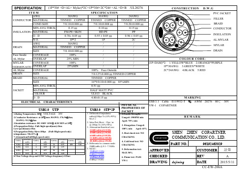
APPROVED CHECKED DRAWING dujiming
CUSTOMER 詮榮
REV
A
DATE
2015/5/11
CC-EW-206A
Unaged: 1500PSI min
Aged: 70% min
MARKING
USB 3.1 Cable E119932-T
AWM 20276 80℃ 30V
VW-1 COPARTNER
REMARK
2. Elongation: Unaged: 100% min Aged: 65%
3. Heat shock test: NO CRACKING
5.80
0.256
0.11
4
0.39
48
1.35
0.512
0.13
8
0.57
96
1.90
0.772
0.15
12
0.76
200
3.20
8.Vbus Voltage drop and GND Voltage drop(max):125mv
USB3.0 STP*2P
1. Differential Impedance: cable@200ps Tr (10%-90%) 90±5Ω
COLOUR CODE: (1P+DAM)*2: 1.YELLOW*BLUE 2.ORANGE*PURPLE
1P*30AWG: 3.GREEN*WHITE 2C*24AWG: 4.BLACK 5.RED
BRAID
MATERIAL SIZE
TINNED COPPER 16*9/0.100.008 ㎜ 85%MIN
SPECIFICATION: (1P*30# +D+AL+ Mylar)*2C+1P*30#+2C*24# +AL +D+B /UL20276
USB3.0 系列产品规格书

Product Specification---------------------xu dong bin11-08-124.2Electrical Performance:Item Test Description Test Methods Requirement4.2.1Low Level ContactResistance EIA364-23B(or MIL-STD-1344A,Method3002.1,Test Condition B)Subject mated contacts assembled inhousing to20mV maximum open circuitat100mA maximumThe object of this test is to detail astandard method to measure theelectrical resistance across a pair ofmated contacts such that the insulatingfilms,if present will not be broken orasperity melting will not occur.1)30mӨMaximum.Initial for VBUSand GND contacts.50mӨMaximum.Initial for all other contacts2)..After test:10mӨMaximumChange4.2.2Insulation Resistance EIA364-21(or MIL-STD-202F,Method302,Test Condition B)Test between adjacent contacts ofmated and unmated connectorassemblies.The object of this test procedure is todetail a standard method to assessthe insulation resistance of USB AF3.0connectors.This test procedure isused to determine the resistanceoffered by insulation connector to a DCpotential current through or on thesurface of the members.1).Initial:1000MӨMinimum2).Aftertest:1000MӨMinimumProduct Specification---------------------xu dong bin11-08-12 4.2Electrical Performance:(Continued)Item Test Description Test Methods Requirement4.2.3DielectricWithstanding Voltage EIA364-20(or MIL-STD-202F,Method301,Test Condition B)Test between adjacent contacts of matedand unmated connector assemblies.The object of this test procedure is to detaila test method to prove that a USB AF3.0connector can operate safely at its ratedvoltage and withstand momentary overpotentials due to switching,surges and/orother similar phenomena.500VACforoneminuteatsealevel1).No flashover or insulationbreakdown2).Leakage current:0.5mA Maximum.4.3Mechanical Performance:(Continued)Item Test Description Test Methods Requirement4.3.1Durability EIA364-09Mate and unmate Connectorassemblies for1500-5000cycles atmaximum rated of200cycles per hour.(standard Durability Class1500cyclesmini,High Durability Class5000cyclesmini)The object of this test procedure isto detail a uniform test method fordetermining the effects caused bysubjecting a USB AF3.0connector tothe conditioning action of inserting andextraction,simulating the expected lifeof the connectors.Durability cycling witha gauge is intended only to producemechanical stress.Durability performedwith mating components is intended toproduce both mechanical and wearstress.1).Shall meet visual requirement,show no physical damage.2).Shall meet requirements of additional tests as specified in TEST SEQUENCE in Section5Product Specification---------------------xu dong bin11-08-124.3.2Mechanical Shock EIA-364-27BSubject mated connector to30G’shalf-sine shock pulses of11msecduration.Three shocks in each directionapplied along three mutuallperpendicular planed for a total of18shocks No discontinuities of1microsecond or long duration.See note4.3.3Vibration EIA-364-28DSubject mated connectors to10~55~10Hz traversed in1minute at1.52mm amplitude2hours each of3mutually perpendicular planes.No discontinuities of1microsecond or long duration.See note4.3.4Connector MatingForceEIA364-13Shall be measured with TENSIONGAUGE or TENSION TESTER.Measure force necessary to mateassemblies at maximum rate of12.5mm(or0.492”)per minute.The object of this test is to detail astandard method for determining themechanical forces required for insertinga USB AF3.0connector.1).Initial:35Newtons(or3.57Kgf)Maximum2).After test:35Newtons(or3.57Kgf)MaximumProduct Specification---------------------xu dong bin11-08-124.3.5Connector UnmatingForce EIA364-13Shall be measured with TENSIONGAUGE or TENSION TESTER.Measure force necessary to mateassemblies at maximum rate of12.5mm(or0.492”)per minute.The object of this test is to detail astandard method for determining themechanical forces required forextracting a USB AF3.0connector.1).Initial:10Newtons(or1.02Kgf)Minimum2).After test:8Newtons(or0.82Kgf)Minimum4.3.6Contact RetentionForce EIA364-35Shall be measured with TENSIONGAUGE or TENSION TESTER in samedirection.1).Initial:0.4Kgf minimum2).After test:0.4Kgf minimumProduct Specification---------------------xu dong bin11-08-12 4.4Environmental Performance:Item Test Description Test Methods Requirement4.4.1Thermal Shock EIA364-32,Test Condition I,(orMIL-202F,Method107G Condition A.)Subject mated connectors to tencycles between–55кto+85к.The object of this test is to determinethe resistance of a USB AF3.0connector to exposure at extremes ofhigh and low temperatures and to theshock of alternate exposures to theseextremes,simulating the wrost caseconditions for storage,transportationand application.1).Shall meet visual requirement,show no physical damage.2).Shall meet requirements of additional tests as specified in TEST SEQUENCE in Section54.4.2Humidity EIA364-31,Test Condition A MethodIII,(or MIL-202F,Method103B TestCondition B.)Subject mated connectors to168Hours(seven complete cycles)The object of this test procedure is todetail a standard method for theevaluation of the properties of materialsused in USB AF3.0connectors asthese influenced by the effects of highhumidity and heat.1).Shall meet visual requirement,show no physical damage.2).Shall meet requirements of additional tests as specified in TEST SEQUENCE in Section54.4.3Salt Spray MIL-STD-202F,Method101D,TestCondition BSubject mated connectors to8hours at35кwith5%-Salt-solutionconcentration.1).Shall meet visual requirement,show no physical damage.2).Shall meet requirements of additional tests as specified in TEST SEQUENCE in Section54.4.4Temperature Life EIA364-17Test Condition3MethodA,Subject mated connectors totemperature life at105кfor120hours 1).Shall meet visual requirement,show no physical damage.2).Shall meet requirements of additional tests as specified in TEST SEQUENCE in Section5xu dong binProduct Specification---------------------11-08-12 5.0Test Sequence:Test Group(a)Sample GroupsTest Item Test Description A B C D E F G H I J K L 4.1.1Examination of product1,131,51,81,3131,513164.2.1Low Level Contact Resistance ,102,42,4254.2.2Insulation Resistance , 2,64.2.3Dielectric Withstanding Voltage4,123,74.3.1Durability74.32Mechanical Shock34.33Vibration44.3.4Connector Mating Force ,84.3.5Contact Unmating Force6,94.3.6Catact Retention Force24.4.1Thermal Shock54.4.2Humidity44.4.3Salt Spray34.4.4Temperature Life(see note c)34.4.5Solderability24.4.6Resistance to Soldering Heat2Number of Test Samples(Minimum)55555555。
- 1、下载文档前请自行甄别文档内容的完整性,平台不提供额外的编辑、内容补充、找答案等附加服务。
- 2、"仅部分预览"的文档,不可在线预览部分如存在完整性等问题,可反馈申请退款(可完整预览的文档不适用该条件!)。
- 3、如文档侵犯您的权益,请联系客服反馈,我们会尽快为您处理(人工客服工作时间:9:00-18:30)。
1.一般事项
General requirements
1.1 适用范围Scope of Application
本插座适用于打印机、彩色液晶电视接收机、电脑以及网络等电子设备
外接数字信号装置之用。
This socket is used by color TV, component stereo, video disc players,
computers and equivalent electronic equipment to connect with external
audio and video device.
1.2 标准状态Standard State
除另规定外,测量应在以下状态进行:
The test should be tested in the following state unless otherwise specified 温度: 15℃~ 35℃
Temperature: 15℃~ 35℃
相对湿度: 45% ~ 70%
Relative Humidity: 45% ~ 70%
气压: 86K pa ~ 106 K pa
Air Pressure: 86K pa ~ 106 K pa
1.3 使用温度范围:-25℃~ +70℃
Operating Temperature Range:-25℃~ +70℃
1.4 环保要求:符合欧盟RoHS 指令的环保要求。
Environmental Requirement:Comply with the EU environmental
requirements ofRoHS directive
2. 额定规格
Rated voltage and current
a.额定电压为:(AC、DC、34 V)
Rated voltage: AC, DC, 34V
b.额定电流为:2.0 A
Rated current: 2.0 A
3. 测试要求
Test Requirements
3.1 外观、机械性能
Appearance & Mechanical Performance:
3.2 电气性能
按中国部标:GB5095.6 的试验11α规定的方法进行试验
插座应能承受温度为-10~+70℃
暴露时间为t =30 分
5 次温度循环作用
The socket shall withstand –10~+700C temperature, exposed time t1=30min, 5 times of temperature cycling, as described in Test 11a GB5095.6
Endurance performance
Attentions:
5.1 装有产品的纸箱或木箱允许用任何方法运输,唯需避免雨雪直接淋袭和机械撞击。
The products packaged in cartons or wooden cases are allowed to move or transport in
anyway, yet shall prevent any exposure in rainfall, snowfall and prevent any echanical
damage.
5.2 产品应存放在环境温度为-10~+40℃,相对湿度不大于80%,周围空气不应有酸
、碱、硫化物、臭氧、氨气及其它对产品有害气体的仓库存。
The products shall be stored in the warehouse where temperature is within –10~400C, relative humidity below 80%, and there are no acidic, alkalescent, sulfide, ozone,
alkaline air or any other corrosive gas in ambient environment,。