德国KOBOLD流量计流量开关PSRPSE
德国科宝KOBOLD压力开关 SCH

德国科宝KOBOLD压力开关SCH
德国科宝KOBOLD Messring GmbH是一家世界领先的工业自动化控制仪表生产企业,公司自1980年由Mr.Klaus J.Kobold先生创立,科宝集团下辖KOBOLD, HEINRICHS等子品牌,以精密的德国制造技术生产的测量仪表迅速赢得了市场,年增长率超过10%。
目前,公司在阿根廷、比利时、德国、中国、英国、法国、意大利、加拿大、荷兰、瑞士、新加坡、奥地利、美国和委内瑞拉设有独资分公司。
在60多个国家通过代理商进行销售。
产品主要在德国、美国、西班牙和匈牙利生产。
科宝集团的核心经营理念是质量第一、客户至上。
科宝公司在数十年的仪表生产和销售过程中,不仅积累了大量的产品及应用经验,也积累了雄厚的产品开发能力,这使得科宝公司不断通过技术创新而壮大。
参数
开关范围:
-1 ... +0,1 bar
-250 ... +100 mbar
1 ... 16 mbar ... 16 ... 63 bar
连接: G ½", G ¼"
Material: copper, 铜, 不锈钢, NBR
介质最高温度: 70 °C
过压、真空压力和差压。
欧柏仪表流量开关不同知识的介绍
欧柏仪表液体流量开关用于感应流经管道的液体流量变化,例如水、乙烯、乙二醇或其它非危害性液体。
当液体流量超过或低于设定的流速时,其单刀双掷开关触点(SPDT)可使一个回路导通,而同时切断另外一个回路。
该流量开关通常使用在需要连锁作用或“断流”保护场所。
特点:1-液体压力可高达1034kPa,使用范围宽2-不锈钢叶片有三节,用于直径25mm~75mm的管线3-可根据需要拆卸叶片的节数,及修整叶片长度4-F61MB附加6英吋叶片,可用于100mm~150mm的管线5-定点可调整,用户可根据系统的需要进行选择。
数字流量开关使用注意事项1、设计、选型①请使用规定的电源电压使用规定以外的电压,是引起开关误动作、损坏、触电和火灾的原因②绝对不要使用超过开关最大负荷的负载③请不要使用会产生浪涌电压的负载开关的输出部分,因为没有浪涌保护装置,所以反向电压会使开关损坏。
当直接驱动继电器、电磁阀等会产生浪涌电压的负载时,要使用内置浪涌吸收元件型号的产品。
④必须注意测定流量、最高使用压力⑤使用超过规定范围流量、会使流量开关损坏。
另外,如果超过最高使用压力使用时,也会使开关损坏。
特别是不要超过规定压力的水冲击点。
降低水冲击的方法:1.使用水冲击缓冲阀,减慢阀的关闭速度。
2.使用橡胶软管等弹性配管、蓄能器,来吸收水冲击压力。
3.尽可能缩短配管长度。
⑥设定时,通常应使被检测管道充满水。
特别是在安装用在水从下向上流动的管道时。
⑤在规定流量范围的量程中,使用本开关。
在测定流量范围之外使用时,不能产生卡曼漩涡,也就不能正常计量。
⑥要注意开关的内部压降。
在规定电压以下使用开关时,会出现,即使流量开关工作正常,但负载不动作的现象。
负载工作电压的确认,应满足下式:电源电压—开关内部电压〉负载工作电压开关的数据,电源断后不消失。
流量开关主要是在水、气、油等介质管路中在线或者插入式安装起到在流量高于或者低于某一个值的时候触发开关输出报警信号 系统获取信号后即可作出相应的执行单元动作。
Honsberg流量开关

解决方案
使用直列活塞式设计的流量开关 HD1K、HR1MV, 使用流量 进行准确监测。 可选多种外型的现场指示表盘。 使用旋钮或滑块就能轻松完成开关点设置,适用于液压润滑 行业。 直列活塞式 HD1K
直列活塞式 HD1K、HRIMV
为客户定制非标型号 , 满足更多要求 可选防爆型号 特别耐脏 , 适用于恶劣环境 Pn 最高达 500bar,温度最高 120℃ 可配智能集成系统 (omni, Flex, EFFI 等) , 现场数字显示, 输出模拟信号、开关量信号。
齿轮流量计 VHZ-...GA...
精确测量高粘度液体 PN200,-25...80℃ 任意安装 无磁性部件 可选铝或不锈钢外壳 模拟信号输出 , 显示 , 开关点 , 适配其他 的变送系列 ( 如 omni, Flex, EFFI…) VHZ 系列齿轮流量计
案例客户名单
上海外高桥电厂 盘山电厂 OMNI 系列集成系统磨煤机润滑
客户困扰
润滑油粘度大。如何精确测量 ? 流量计信号需要连入 DCS 系统 , 需要标准电流 信号。如何解决? 现场工人需要查看实时流量大小。如何解决?
解决方案
选择容积测量来计算流量的齿轮式流量计可以 精确测量润滑油 , 忽视粘度的影响。 可选配集成系统 Omni,满足客户更多使用要 求。可变送输出标准电流信号、现场数字显示、 还可设置 2 个开关点。
PN 25 25 25 25 25 16 16 16 16 16
开关值 l/min H2O 固定开关选择范围 1-10 1-10 4-20 10-40 20-60 30-100 50-150 100-200 180-330 300-600
L mm 150 150 150 150 150 156 156 156 156 156
Kobold ZDM正压流量计说明书
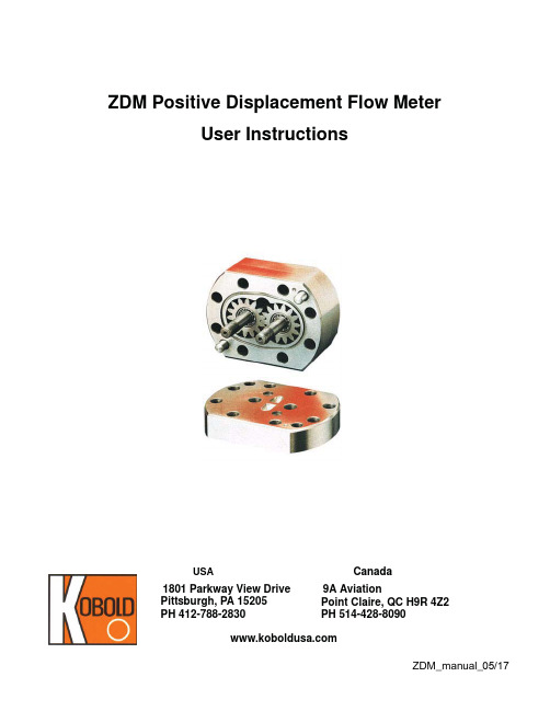
User InstructionsUSA 1801 Parkway View Drive Pittsburgh, PA 15205PH 412-788-2830Canada9A AviationPoint Claire, QC H9R 4Z2PH 514-428-8090ZDM Positive Displacement Flow MeterTable of ContentsTopic Page1.0General . . . . . . . . . . . . . . . . . . . . . . . . . . . . . . . . . . . . . . . . . . . . . . . . . . . . . . . 12.0Description. . . . . . . . . . . . . . . . . . . . . . . . . . . . . . . . . . . . . . . . . . . . . . . . . . . . . 22.1Principle of Operation. . . . . . . . . . . . . . . . . . . . . . . . . . . . . . . . . . . . . . . 22.2Specifications. . . . . . . . . . . . . . . . . . . . . . . . . . . . . . . . . . . . . . . . . . . . . 22.2.1Mechanical Data. . . . . . . . . . . . . . . . . . . . . . . . . . . . . . . . . . . . . 2Filtration Requirements. . . . . . . . . . . . . . . . . . . . . . . . 3Electrical Data. . . . . . . . . . . . . . . . . . . . . . . . . . . . . . . . . . . . . . . 32.2.3Accuracy. . . . . . . . . . . . . . . . . . . . . . . . . . . . . . . . . . . . . . . . . . . 32.2.2Pressure Loss. . . . . . . . . . . . . . . . . . . . . . . . . . . . . . . . . . . . . . . 43.0Installation Instructions. . . . . . . . . . . . . . . . . . . . . . . . . . . . . . . . . . . . . . . . . . . . 43.1Mechanical Installation. . . . . . . . . . . . . . . . . . . . . . . . . . . . . . . . . . . . . . 43.1.1Installing the Mounting Plate. . . . . . . . . . . . . . . . . . . . . . . . . . . . 43.1.2Attaching the Flow Sensor to the Mounting Plate. . . . . . . . . . . . 43.1.3Bolt Torque Specifications . . . . . . . . . . . . . . . . . . . . . . . . . . . . . 43.1.4Connecting Piping to the Sensor . . . . . . . . . . . . . . . . . . . . . . . . 53.2Electrical Connections . . . . . . . . . . . . . . . . . . . . . . . . . . . . . . . . . . . . . . 54.0Operating Instructions . . . . . . . . . . . . . . . . . . . . . . . . . . . . . . . . . . . . . . . . . . . . 64.1Turning the Unit On . . . . . . . . . . . . . . . . . . . . . . . . . . . . . . . . . . . . . . . . 64.2Flow Measurement. . . . . . . . . . . . . . . . . . . . . . . . . . . . . . . . . . . . . . . . . 64.3Turning the Unit Off . . . . . . . . . . . . . . . . . . . . . . . . . . . . . . . . . . . . . . . . 75.0Arrival of Damaged Equipment . . . . . . . . . . . . . . . . . . . . . . . . . . . . . . . . . . . . . 76.0Maintenance. . . . . . . . . . . . . . . . . . . . . . . . . . . . . . . . . . . . . . . . . . . . . . . . . . . . 77.0Need Help with your ZDM Sensor? . . . . . . . . . . . . . . . . . . . . . . . . . . . . . . . . . . 7Appendix A: Pressure Loss vs. Flow Rate at Various Viscosities . . . . . . . . . . . 9List of DiagramsDiagram 3.2.1ZDM Wiring Schematic. . . . . . . . . . . . . . . . . . . . . . . . . . . . . . . . 5 Diagram 4.2.1ZDM Frequency Output Waveform. . . . . . . . . . . . . . . . . . . . . . . 6List of TablesTable 1:ZDM Wetted Parts . . . . . . . . . . . . . . . . . . . . . . . . . . . . . . . . . . . 2 Table 2:Volume per Pulse for Various ZDM Ranges. . . . . . . . . . . . . . . . 7ZDM KOBOLD ZDM POSITIVE DISPLACEMENT FLOWMETERUser InstructionsCAUTION:For safety reasons, please read the cautionary information located at the end of this manual, before attempting installation.1.0GeneralCongratulations on your purchase of a Kobold ZDM Positive Displacement flowmeter.The ZDM is one of the most precise and reliable low volume, liquid flow measuringproducts available today.The ZDM operates on the viscosity and density independent volumetric principle. Twogears are brought into counter-rotation by the force of liquid moving past the gears along the meter’s housing. Engagement of the gear teeth with the housing walls entraps adefined volume in the cavity between the gear teeth. A detector counts the gear teeth as the cavities empty into the exit port. The precision of the meter is defined by the gearcavity volume. The ZDM can meter volumes as low as 0.02 CC (cubic centimeters.) This ultra-high precision is coupled with bi-directional flow capability,viscosity compatibility to 100,000cSt and a mechanical robustness capable of pressures to 6500PSIG (450 BAR).The ZDM is the ideal choice for difficult clean liquid applications involving media withlubricating properties ranging from very slight, to extensive.ZDM 22.0Description2.1Principle of Operation The ZDM operates on the volumetric displacement principle. The meter moves pockets of liquid from the inlet port to the exit port in discrete segments of known volume. These pockets are defined by the space between adjacent gear teeth and the internal housing wall.As liquid enters the meter, the inlet cavity fills. The liquid pressure forces the meter’sgears to rotate from the gear mesh-point inwards.The gear teeth cavities fill with liquid in the inlet side of the meter and remain filled as the teeth come into near-contact with the meter’s interior walls. The gear teeth then drag the liquid to the exit cavity at the opposite side of the meter. This process causes the exit cavity to fill since the liquid is squeezed out of the spaces between the teeth at the gear mesh point. The liquid then flows out the exit port of the meter.A proximity sensor in the housing senses the passage of individual gear teeth. Since the passage of a tooth signals the passage of its trailing space (filled with liquid), the system as a whole signals with an electrical pulse every time a displaced amount is emptied into the exit port. The resolution of the ZDM is, therefore, determined by the volume between the gear teeth.This entire procedure is completely independent of the properties of the liquid, making the system applicable to a wide variety of media (even liquids with dynamically changingcharacteristics.) The only limitations to the system are mechanical ones. Since metal to metal contact is involved, the liquid must have some lubricating properties in order to prevent excessive wear of the gear teeth. If the gear teeth wear down, liquid will leak past them excessively. This excess leakage will degrade the meter’s accuracy. The required Another limitation is caused by the relatively high pressure loss inherent to positivedisplacement technology. The pressure loss through the ZDM becomes unacceptable if the media viscosity exceeds 100,000 cSt.2.2Specifications2.2.1Mechanical DataTable 1: ZDM Wetted PartsWettedComponentNominal Construction MaterialCast Iron (ZDM-X1XX) Stainless Steel (ZDM-X 2XX)Sealsamount of media lubricity is very slight.HousingCast Iron SS GearsSS SS Bearings SS SS).0).03ZDM Filtration RequirementsZDM-XX02, -XX04, -XX07:10P M (1600 mesh)ZDM-XX08, -XX09:20P M (750 mesh)ZDM-XX10, -XX20, -XX40:50P M (250 mesh)Maximum Pressure Rating:Cast Iron: 4500 PSIGSt. Steel: 6500 PSIG Maximum Temperature RatingStandard:-40 to 248°FAccuracy:±0.3% of reading (Ranges: 02-40)±0.5% of reading (Range:50)(viscosity >20 cSt)Repeatability:±0.05% of readingElectrical DataSensor Type:Qty. 2 Push-Pull Outputs (Channels A & B)A &B Signals are 90° out of phase.Phase difference can be used to determineflow direction using suitable receiving equipment.Power RequirementsVoltage (V cc):10-28 VDCCurrent:80mA max. @ 24 VDCPower: 1.92 W max. @ 24 VDCOutput SignalType:DC voltage pulseForm:Square waveAmplitude:Low = GND, High = V cc - 1.0 VDCZDM42.2.2Pressure LossPressure loss is a function of the viscosity of the liquid being metered, andits rate of flow. Detailed pressure loss information may be found inAppendix A of this manual.3.0Installation InstructionsCAUTION:For safety reasons, please read the cautionary information located at the end of this manual, before attempting installation.3.1Mechanical InstallationThe ZDM is shipped from the factory in two pieces (not counting the electricalconnecting cable or the sensor-mounting plate fastening bolts)consisting of themounting plate and the sensor body. We recommend that you install the mountingplate first, then attach the sensor and finally connect the piping.3.1.1Installing the Mounting PlateThe sensor may be rigidly held in place on your installation through use ofthe four threaded holes in the base of the mounting plate. These holes aremetric and sized as follows:ZDM-XX02 to ZDM-XX08:M6 (6 mm metric)ZDM-XX09 to ZDM-XX40:M8 (8 mm metric)3.1.2Attaching the Flow Sensor to the Mounting PlateThe sensor comes supplied with a set of four steel bolts and O-rings forfastening the sensor to the mounting plate.3.1.2.1Install the O-rings into the grooves in the body of the sensor.3.1.2.2Position the sensor on the mounting plate so that the bolt holes inthe sensor line up with the bolt holes in the mounting plate.3.1.2.3Insert the bolts into the bolt holes and thread into mounting plateuntil they are finger tight.3.1.2.4With an appropriately sized wrench, tighten the bolts to the speci-fied torque in a diagonal bolt tightening pattern.3.1.3Bolt Torque SpecificationsThe following are the nominal torque specifications for all ZDM bolts.Meter Model Torque (N-m)Torque (lb.-ft.)ZDM-XX02to ZDM-XX08:1511.1ZDM-XX09 to ZDM-XX20: 3525.8ZDM-XX40:12088.55ZDM3.1.4Connecting Piping to the SensorThe procedure for attaching piping to the sensor depends on the type ofthread that was ordered with the sensor. The most common thread inNorth America is NPT (series ZDM-3XXX and ZDM-4XXX sensors.)Occasionally, the European pipe thread (BSP) is ordered because of itssuperior leak resistance. Series ZDM-1XXX and ZDM-2XXX sensors allhave BSP threaded fittings.If the fittings on your ZDM are incorrect for your application,you cancorrect the situation by purchasing a different mounting plate.3.1.4.1If you have NPT threads, coat the threads with a paste type pipesealant before threading into the mounting plate.We recommend that PTFE tape NOT be used since pieces of itmay find their way into the sensor, possibly causing the gears tobind. Should you have no alternative to PTFE tape,make sure thatit is properly trimmed and does not extend beyond the first threadon your pipe fittings.3.1.4.2If you have BSP threads, place the sealing gaskets over the endsof your pipe fittings and thread fittings into the mounting plate.3.2Electrical ConnectionsThe standard ZDM operates on a power supply of: 10-28 VDC.Diagram 3.2.1:ZDM Wiring SchematicZDM64.0Operating Instructions4.1Turning the Unit OnSupply power.4.2Flow MeasurementThe ZDM transmits a frequency based electronic signal in response to flowthrough its mechanism. This signal takes the form of a square wave, theamplitude of which is the supply voltage(V cc) minus 1.0 VDC. A representation ofthe waveform is given in Diagram 4.2.1, "ZDM Frequency Output Waveform", onpage6. Each pulse in the transmitted signal represents a fixed quantity of liquidpassing through the meter. The exact amount of liquid represented by each pulseis a function of the range of the meter. To determine the sensitivity of your meter,consult Table 2, "Volume per Pulse for Various ZDM Ranges", on page 7.Diagram 4.2.1:ZDM Frequency Output WaveformTable 2: Volume per Pulse for Various ZDM RangesZDM Model Number Range (GPM)Frequency(Hz)Pulses per GallonZDM-XX020.0005 - 0.53 1.577-1671.90189,272ZDM-XX040.0011 - 1.06 1.735-1671.9094,636ZDM-XX070.0026- 2.64 1.640-1665.5937,854.4ZDM-XX080.0053 - 4.76 1.672-1501.5618,927.2ZDM-XX090.0079 - 10.57 1.246-1667.179,463.6ZDM-XX100.0132 - 21.130.833-1333.113,785.44ZDM-XX200.0264 - 31.700.833-1000.001,892.72ZDM-XX400.2642 - 66.00 4.167-1041.00946.364.3Turning the Unit OffRemove power.5.0Arrival of Damaged EquipmentYour instrument was inspected prior to shipment and found to be defect-free. If damage is visible on the unit, we advise that you carefully inspect the packing in which it wasdelivered. If damage is visible, notify your local carrier at once.The carrier is liable for a replacement under these circumstances.If your claim is refused, please contactKOBOLD Instruments.6.0MaintenanceThe ZDM is continuously lubricated by the medium flowing through its internalcomponents,so no extra lubrication is required.Please note the following typical filtration requirements:ZDM-XX02 to ZDM-XX07:10 umZDM-XX08 to ZDM-XX09:25 umZDM-XX10 to ZDM-XX40:50 umMake sure that the filter is kept in proper functioning condition. The frequency of filterreplacement and maintenance will depend on the level on cleanliness of the meteredliquid.The only wear component in the ZDM are the gear teeth. The gear teeth will wear withtime. The rate of wear depends on the time of operation and the abrasion/lubricationproperties of your measured liquid. We recommend that users perform a periodic (every six months is suggested) check of the meter calibration. The most effective way to do this is to use a calibrated container, a timer and accurate weight scale.7.0Need Help with your ZDM Sensor?Call one of our friendly engineers at 412-788-2830.Appendix A: Pressure Loss vs. Flow Rate at Various ViscositiesZDM1011ZDMZDM12ZDM-0010 Pressure LossCAUTIONPLEASE READ THE FOLLOWING WARNINGS BEFORE ATTEMPTING INSTALLATION OF YOUR NEW DEVICE. FAILURE TO HEED THE INFORMATION HEREIN MAY RESULT IN EQUIPMENT FAILURE AND POSSIBLE SUBSEQUENT PERSONAL INJURY.ZDM16•User's Responsibility for Safety: KOBOLD manufactures a wide range of process sensors and technologies. While each of these technologies aredesigned to operate in a wide variety of applications, it is the user'sresponsibility to select a technology that is appropriate for the application,to install it per these installation instructions, to perform tests of theinstalled system, and to maintain all components. The failure to do so couldresult in property damage or serious injury.•Proper Installation and Handling: Use a proper sealant with allinstallations. Never overtighten fittings. Always check for leaks prior tosystem startup.•Wiring and Electrical: A supply voltage of: 10-28 VDC is used to power the ZDM. The sensor systems should never exceed this rating. Electricalwiring of the sensor should be performed in accordance with all applicablenational, state, and local codes.•Temperature and Pressure: The ZDM is designed for use in mediatemperatures from -40 to 248°F, and for use at pressures up to 6500 PSIG,depending on model. Operation outside these limitations will causedamage to the unit and possible personal injury.•Material Compatibility:Check your model number with the wettedmaterials specifications of this manual. Make sure that the model whichyou have selected is chemically compatible with the application liquids.While the electronics housing is liquid resistant when installed properly, it isnot designed to be immersed. It should be mounted in such a way that itdoes not normally come into contact with fluid.•Flammable, Explosive and Hazardous Applications: The ZDM with option Ex or EXA are intrinsically safe and are the only units which are tobe used in hazardous locations. Other ZDM models should not be used inareas where an explosion proof design is required.•Make a Fail-Safe System: Design a fail-safe system that accommodates the possibility of switch or power failure as well as operator error. In criticalapplications, KOBOLD recommends the use of redundant backup systemsand alarms in addition to the primary system.。
德国kobold科宝指针式挡板流量开关 DWU, DWN

德国kobold科宝指针式挡板流量开关DWU, DWN
KOBOLD新型流量监视器DWU/DWN是基于靶式流量计的原理工作的。
流动的介质作用在弹簧上,使得挡板在流动方向上发生偏移。
不锈钢风箱系统将介质与测量单元分开。
挡板的偏移转移到测量单元。
在测量单元,一旦达到或者不足设定好的开关点时,微动开关和指示灯开始工作。
因此,通过开关点指示灯,流量的变化会明确的被显示出来。
同时,设计成3孔的转换开关出发。
从挡板到测量单元传输的动作,即位移偏离技术是最安全的系统。
如果T片被石灰、异物或污物堵塞,系统会用“no flow”来回应。
当系统实际上没有流动时,系统就几乎不可能挂在一个位置上。
参数
开关范围: 1 - 25 l/min ... 300 - 3600 m³/h 水
连接: G ⅜... 2, ⅜... 2" NPT, 法兰DN10 ... DN50,
ANSI ⅜... 2", weld-on 法兰DN40 ... DN500
材质:
铜, 不锈钢(DWU)
铜, 不锈钢, PVC (DWN)
耐压: PN 16
介质最高温度: 100°C
精度: ±3 ... ±5 % 满量程
适用于液体介质·污染介质。
德国kobold科宝带定量控制器的数显流量计DF-DL

德国kobold科宝带定量控制器的数显流量计DF-DL
DF-DL 流量计电子装置将旋转叶片产生的频率信号转换为显示在LCD 显示屏上部的数字流量读数、底行显示的总体积流量和可扩展的模拟量输出信号。
包括两个带SPDT 开关的继电器,可用于各种功能。
可根据需要为每个继电器设置可自由调节的开关点、滞后、窗口点和开启/关闭延迟。
一个继电器(S1) 可用于执行流量监控、总体积流量监控和定量体积流量或泵控制。
第二个继电器(S2) 通常用于配料控制,一旦达到所需的配料量就会打开。
定量控制过程也可以立即中断,然后使用面板上的Start/Stop键快速恢复。
参数
测量范围
0.08 - 0.5 l/min ... 40 - 160 l/min 水
机械连接
G ⅛... G 1½, 法兰DN15 ... DN50
耐压
6 / 10 / 16 / 100 bar
耐温
80 ℃
接液材质
镀镍黄铜、SS、聚砜、PVDF、FKM、NBR 精度
±2.5% 满量程
适用介质
液体
特点
速率、总量显示和定量控制
LED显示屏
减法和加法计数器
1个定量控制继电器
1 个可自由编程的继电器
输出0(4)-20 mA, 0-10 VDC
货期短,交货快。
德国kobold科宝螺杆式流量计 OMG, OMH, OMS

德国kobold科宝螺杆式流量计OMG, OMH, OMS
基于容积式流量计原理的KOBOLD的螺纹式体积流量计是为了响应测量和控制粘性介质的需要而开发的。
它专门用来测量无摩擦的粘性介质的。
在1-5000 mm 2 /s之间的粘度变化对测量结果的精度没有影响。
螺纹式体积流量计满足了对更高精度、可靠性和经济效率的严格要求。
两个具有圆形轮廓的锭子构成了螺纹式容积流量计的基础。
高精度制造的锭子,每一端都有滚珠轴承支撑。
轴向强迫测量介质使锭子匀速转动。
旋转运动被感应接近传感器或霍尔效应传感器拾取,并转换成一个频率信号。
通过容积测量的测量腔,获得了对所传递流量的精准测量。
与计算单元相结合,KOBOLD螺纹式体积流量计成为适用于粘性介质的灵活的测量单元和控制系统。
参数
测量范围:
0.1 - 10 l/min ... 50 - 5000 l/min 液体
1 - 1000000 mm²/s 粘度
精度: ±0.1 % 量程(1:100), ±0.3 % 量程(1:150)连接: G ½...6 内螺纹, 法兰DN15 (100)
工作条件
耐压: 420 bar
介质最高温度: 200°C
输出: 1x 脉冲
电气连接: 聚四氟乙烯-线缆直角插头
电缆箱/ 1 m 聚四氟乙烯线缆,pvc线缆
供电: 10 ... 30 VDC
材质: 耐酸硅钢, 不锈钢
无脉动的测量原理,高粘度,
自洁式测量,选择性安装。
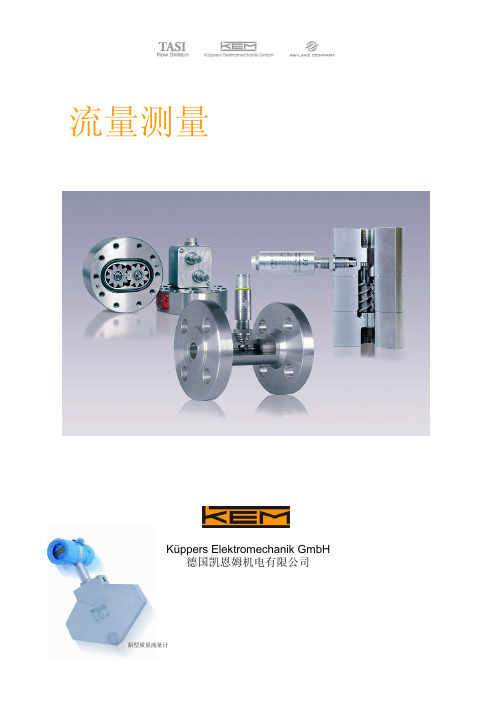
德国KEM流量计样本
2
Hermle 5轴加工中心
另外,工厂还开发建造了许多流量计标定设备。1993 年在卡尔斯菲尔德建造了一个 DKD(德国标定服务 中心)附属的流量标定实验室,并且得到了 PTB(物理 技术委员会)的认证。
KEM在2007年的销售额为910万欧元,其中出口占到 60%。全球的市场覆盖了许多不同的领域,像汽车行 业,聚氨酯行业,钢铁,化工,石化和制药等行业。 KEM流量计应用在测试台,填装线,批量灌装,喷 漆等系统。
涡轮流量计
◄ 高压应用 直到 4000 bar
涡轮流量计用于水流切割,海上平台和化工等应用 场合。根据流量条件还可提供特殊的高压法兰和螺 纹连接。
高温应用 ► 直到 +350 °C
例如温度控制系统中的涡轮流量计
◄ 消耗量测量 例如化工溶剂,去离子水
带内部信号拾取和 ATEX 防爆的涡轮流量计。
5
螺杆流量计/齿轮流量计/气体质量计/浊度计
从 2005 年 12 月份开始,KEM 成为美国 TASI 集团 的一员。和我们在美国长期的合作伙伴 AW 公司和 米尔沃基的 LAKE Monitors 公司共同成立 TASI 的 “流量家族”。
各种液体和大密度的气体 科里奥力质量流量计
选型指南
涡轮流量计
低粘度液体
微小流量计
第4页
齿轮流量计
第5页
分离型
4
LFM微小流量计
涡轮流量计 间接式体积流量测量
用于燃料油,轻质燃料油,化学溶剂,自来水,去离子水,制 药液体,液化气等 • 测量范围: 0.03...48,000 l/min • 粘度: 0.1...150 mm²/s • 线性: ±0.15% 测量值 • 压力: 最大 630bar • 温度: –273°C...+350°C
- 1、下载文档前请自行甄别文档内容的完整性,平台不提供额外的编辑、内容补充、找答案等附加服务。
- 2、"仅部分预览"的文档,不可在线预览部分如存在完整性等问题,可反馈申请退款(可完整预览的文档不适用该条件!)。
- 3、如文档侵犯您的权益,请联系客服反馈,我们会尽快为您处理(人工客服工作时间:9:00-18:30)。
德国KOBOLD流量计/流量开关PSR/PSE
德国KOBOLD Messring GmbH 是一家在测量和控制技术领域内国际知名的企业。
她是由德国著名工程师KLAUS J.KOBOLD于1980年创建并发展壮大起来的.公司总部在德国,工厂在德国和美国, 并在比利时、英国、法国、荷兰、美国、加拿大、奥地利、瑞士、阿根廷和中国设有独资公司。
德国KOBOLD公司致力于开发、生产和销售流量、压力、温度、物位等物理参数的测控仪器仪表。
产品以其品种多、技术更新快的特点, 广泛应用于工业各个领域。
德国KOBOLD公司强大的生命力在于其产品种类的不断扩充并针对用户需求提供优质经济的仪器仪表。
小流量转子流量计/流量开关;转子流量计/流量开关;挡板式流量计/流量开关;带旋转部件的流量计;无活动部件的流量计;流量镜;
压力表;压力传感器;压力开关;液位开关/物位开关;液位计;温度开关/恒温器;温度计/温度传感器;ph计,ORP 计,电导率计;湿度计;
浊度计;用于食品测量和控制仪表.
快速提供德国KOBOLD系列产品
小流量转子流量计/流量开关
小流量转子流量计KSV
塑料转子流量计和流量开关KSK
小流量转子流量计KFR
带观察窗的流阿量开关SVN/KSR
玻璃转子流量计KDF/ KDG
转子流量计和流量开关SWK
全金属转子流量计和流量开关KMI
塑料转子流量计和流量开关KDK
转子流量计/流量开关
粘度补偿型转子流量计VKP
塑料转子流量计和流量开关KSM
金属转子流量计和流量开关DSV
玻璃转子流量计和流量开关KhN
全金属转子流量计和流量开关SMN
全金属转子流量计和流量开关SMO/SMW
粘度补偿型全金属转子流量计和流量开关VKG
粘度补偿型全金属转子流量计和流量开关VKM
并联油路分流阀BVB
高精度全金属转子流量计和流量开关KDM
挡板式流量计/流量开关
挡板式流量开关PSR/PSE
挡板式流量开关PPS
挡板式流量开关FPS
挡板式流量计和流量开关DPT
挡板式流量开关DWN
挡板式流量计和流量开关DWU
挡板式流量计DWD
挡板式流量计和流量开关DPR
挡板式流量开关LPS
小流量旋叶式流量计DPL
小流量旋叶式流量计DPM
涡轮流量计DRS
带旋转部件的流量计
小流量旋叶式流量计DTK
小流量涡轮流量计SFL
小流量旋叶式流量计KFF
活塞式流量计LFM
旋叶式流量计DRh
旋叶式流量计DRG
涡轮流量计DPE
涡轮流量计DRB
带累积的旋叶式流量计DF
旋叶式流量计DFT
带累积和批处理的旋叶式流量计DFB
带累积的涡轮流量计EDM =
高精度涡轮流量计PEL
涡轮流量计TUV
塑料涡轮流量计TUR
活塞式流量计DRZ
椭圆齿轮式流量计OVZ
螺杆式流量计OME
铝壳齿轮流量计KZA
螺杆式流量计OM..
齿轮流量计DZR
通用数字显示表ADI
面板安装数显表DAG
通用批量控制器ADI-Z
带批处理和累积的面板安装数显表DAG-AXI 频率转换仪FMU
无活动部件的流量计
热式流量开关KAL-D
热式流量开关KAL
热式流量计流量开关KAL-K
气体热式流量开关KAL-L
热式气体质量流量计MFC
气体质量流量计WFM
质量流量计和流量积算仪PMS
插入式电磁流量计PME
电磁流量计,流量监视器,流量积算仪DMI 电磁流量计和流量积算仪PMG/PMH
振荡式流量计DOG
小流量涡街流量计和流量开关DVZ
涡街流量计KUV
涡街流量计PWL
流量镜
带自清洁功能的旋叶式流量视镜DAA
旋叶式流量视镜DAh
旋叶式流量视镜DAF
旋叶式流量视镜DIh
挡板式流量视镜DAK
带刻度的挡板式流量视镜DAZ
浮球式流量视镜DAB
浮球式流量视镜DKB
压力表
全不锈钢压力表MAN-R
带模拟输出的全不锈钢压力表MAN-Z
差压表MAN-D
数字压力表MAN-S
膜片式压力表MAN-P
波登管式压力表MAN-R
压力传感器
电子式压力开关PDD 、
带数字显示的压力变送器PDA
带前置膜片的薄膜式压力传感器SEN-33
带内置膜片的薄膜式压力传感器SEN-33
陶瓷式压力传感器SEN-8
带前置膜片的压阻式压力传感器SEN-32
带内置膜片的压阻式压力传感器SEN-32
精密压力传感器SEN-33
面板安装数显表DAG
可插拔式数字显示表AUF
压力开关
用于蒸汽的压力开关SCh-DWA
差压开关SCh-DDCM
用于中性气体的压力开关/差压开关SCh-hCD, SCh-DPS 用于腐蚀性气体/液体的压力开关SCh-DNM
通用型压力开关SCh-DCM
带不锈钢感压元件的压力开关SCh-DNS
用于气体的压力开关SCh-DGM, SCh-DWR
电子式压力开关PDD
液位开关/物位开关
旁路式液位开关NBA, NBE
叶轮式物位开关ND
音叉液位计NWS
微波液位开关LNM
电容式液位开关LNZ
电容式液位开关NTS
电导液位开关NEh
电导式液位开关(WhG) NEW
电导式液位开关NEK
电导式液位开关NES
电导式液位计用继电器NE
塑料浮子式液位开关NKP
隔膜式液位开关NMF
浮球式液位开关N
侧装浮球式液位开关NS
金属浮子式液位开关NV
光电液位开关OPT
无线电液位开关NhF
浮球液位开关NSP, NST, NSE
超声波液位开关(夹持式) NDW
超声波液位开关NQ
振动式物位开关NVI
浮球式液位开关NGS
适用于液体
液位计
液位传感器NM
磁致伸缩式液位计NMT
微型旁路式液位计NBK-M
低成本的旁路式液位计NBK-01 超声波液位计NUS
深井探头NTB
膜片式液位计NPF
控制和显示设备DFA, DFM, DST 温度开关/恒温器
电子温度开关TDD
温度开关TWR
温度开关TRS
防冻毛细管恒温器TEA-F, -K
室内用恒温器TEA-R,-A
杆式恒温器TEA-L, -S
工业用恒温器TER
温度计/温度传感器
贴面式热电阻TWA
双金属温度计(1级) TBI
双金属温度计(2级) TBI
数字式温度计DTM
手持数字温度计TD
专业级手持数字温度计S. TD
面板安装数显表DAG
插入式温度传感器TMA
螺纹安装热电偶TTE
插入式热电阻TWE
插入式热电偶TTE
数字式温度传感器TDA
插入式热电阻TWE
毛细管温度计TNF
手持式红外温度计TIR-h
红外温度计TIR-S
铠装热电偶TTM
铠装热电阻TWM
玻璃温度计TGL
顶部安装变送器TUM-K
机架安装的温度变送器TUM-S
可插拔式数字显示表AUF
充氮温度计TNS
柴油机用充氮温度计TND
温包套管TSh
温度传感器TSA
卡口固定热电偶TTE
热电偶(DIN标准) TTD
热电阻(DIN标准) TWD
卡口固定热电阻TWM
无测量死区的管道式温度传感器TWP ph计,ORP计,电导率计
充液式ph电极APS-X2Q
凝胶式ph电极APS-X1Q
凝胶式ph电极APS-Z
凝胶式ORP电极ARS-Z
电导式电导率探头ACS-X
电导式电导率探头ACS-Z
ph和ORP变送器APM-X
ph变送器APM-Z
ORP变送器
电导率变送器ACM-X
电导率变送器ACM-Z
塑壳ORP电极ARS-X5K
湿度计
温度/湿度变送器(吸附式) AFh-G
温度/湿度变送器(电容式) AFK-E
恒湿器AFS-G3
恒湿器AFS-G1
室内用恒湿器AFS-G2
浊度计
浊度计LAT-N1
浊度计LAT-N2
浊度计LAT-N3
浊度计ATA-K
浊度计ATS-K
用于食品测量和控制仪表
小流量旋叶式流量计DPL
热式流量开关KAL-K
超声波流量开关LDU
超声波原理
电磁流量计,流量监视器,流量积算仪DMI
全不锈钢带膜片密封器的压力表MAN-R
Digital Pressure Gauge with Diaphragm Seal MAN-S 带膜片密封器的压力传感器SEN
电导式液位开关LNK-K
电导式液位开关LNK
音叉液位计NWS
微波液位开关LNM
电容式液位开关LNZ
液位计LNP
静压式液位计LPC
静压式液位计用液位显示器LPA
充氮温度计TNS
毛细管温度计TNF
温包套管TSh
数字式温度计DTM
专业级手持数字温度计S. TD
电阻式温度传感器LTS-NK
电阻式温度传感器LTS
无测量死区的管道式温度传感器TWP
浊度计LAT-N1
浊度计LAT-N2
浊度计LAT-N3
电导率计LAL
电池电源的数字显示表LZA
卫生连接管件LZE
卫生焊接管件LZE-NR
电子式压力开关PDL
真空开关SCh-VCM。