西门子温控阀说明书自动化
西门子2-口和3-口区域阀门产品说明说明书
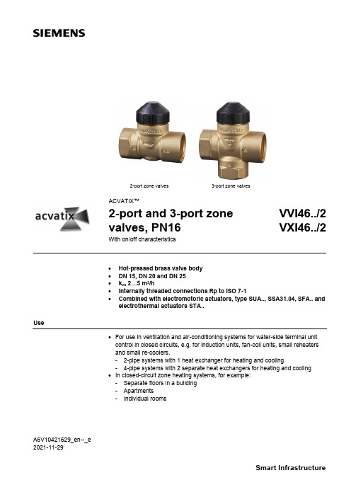
A6V10421629_en--_e 2021-11-292-port zone valves3-port zone valvesACVATIX™2-port and 3-port zone valves, PN16VVI46../2 VXI46../2With on/off characteristics• Hot-pressed brass valve body • DN 15, DN 20 and DN 25 • k vs 2…5 m 3/h• Internally threaded connections Rp to ISO 7-1•Combined with electromotoric actuators, type SUA.., SSA31.04, SFA.. and electrothermal actuators STA..Use• For use in ventilation and air-conditioning systems for water-side terminal unit control in closed circuits, e.g. for induction units, fan-coil units, small reheaters and small re-coolers.- 2-pipe systems with 1 heat exchanger for heating and cooling- 4-pipe systems with 2 separate heat exchangers for heating and cooling • In closed-circuit zone heating systems, for example: - Separate floors in a building - Apartments- Individual rooms2 / 10Type summaryTypeStock numberDNConnections PN classk vsA →AB [m 3/h]VVI46.15/2 S55249-V106 15 Internally threaded Rp162.15VVI46.20/2 S55249-V107 20 3.5 VVI46.25/2 S55249-V108 25 5.0TypeStock numberDNConnections PN classk vs 1) AB →A [m 3/h]k vs 1) AB →B [m 3/h] VXI46.15/2 S55249-V109 15 Internally threaded Rp162.151.5 VXI46.20/2 S55249-V110 20 3.52.5 VXI46.25/2 S55249-V111 25 5.03.5 VXI46.25T/2S55249-V112255.54.51)The k vs values in bypass B of the 3-port valves represent only 70 % of the k vs value in the straight-through control path AB → A. This compensates for the flow resistance of the heat exchanger or radiator, so keeping the overall flow rate100 as constant as possible.k vs = Nominal flow rate of cold water (5…30 °C) through the fully open valve (H 100), by a differentialpressure of 100 kPa (1 bar)OrderingWhen ordering, please specify the quantity, product name and number.The valves and actuators are delivered in separate packaging.The actuator SUA21/3, SSA31.04, SFA.. and STA.. must be ordered separately.The AL50 supporting ring (necessary for combination with SFA.. or SUA..) is included in the delivery of V..I46…See Revision number overview Revision number overview on page 10.ExampleProduct number Stock number Product nameQuantityVXI46.15/2S55249-V1093-port zone valve, PN16 DN15, kvs 2.15 1DeliveryRev. no.3 / 10Equipment combinations∆p max = Maximum permissible differential pressure across the valve’s control path, valid for the entireactuating range of the motorized valve (maximum recommended operating differential pressure) For noiseless operation, the value of 100 kPa should not be exceeded.∆p s = Maximum permissible differential pressure at which the motorized valve will close securelyagainst the pressure (close off pressure)1) ∆pmax(AB-B) is 50 kPa for VXI46.25T/21) SPST = single pole, single throw2)SSA31.04 could not be used with VVI46.25T/24832Z 01Technical design / mechanical design• Disc throttling element• Seat ring embedded in through-port• Seat machined into through-port and bypass• Reservoir for continuous lubrication of sealing rings •Return spring (to open position)Actuator overview4 / 10SizingExample:100 = 0.27 l/s ∆p v 100 = 9 kPak vs value required = 3.5 m 3/h∆p v 100= Differential pressure across the fully open valve and the valve's control path A → AB (2-port valves), AB → A (3-port diverting valves) by a volume flow100100= Volume flow through the fully open valve (H 100)∆p max= Maximum permissible differential pressure across the valve's control path, valid for theentire actuating range of the motorized valve100 kPa =1 bar≈10 mWC 1 m 3/h = 0.278 l/s water at 20 °C5 / 10Engineering notesRefer to Mounting notes and Commissioning notes . It is NOT allowed to put a shut off at the bypass port B.A strainer should be fitted upstream of the valve. This increases reliability.The direction of flow MUST be as indicated by the arrow, from A → AB.The direction of flow MUST be as indicated by the arrow, from AB → A and AB → B (diverting valves).RecommendationWarningWarning6 / 10Mounting notesThe specified direction of flow must be observed in all cases (refer to Engineering notes ).The mounting instructions 74 123 0114 0 B are enclosed with the packaging. The valve and actuator are easily assembled directly on site. There is no need for special tools or calibration.The AL501) supporting ring must be put into position before mounting the actuator SFA.. and SUA.. onto the valve.1) Included in deliveryOrientationAL50 supporting ringSIEMENSkvs5.0XYYMMAA 6V 10421629Z 017 / 10Commissioning notes In the straight-through control path A → AB, respectively AB → A the valve is opened by a return spring.The straight-through path can be closed manually with the manual adjustment button.With 3-port valves, this method can be used to open bypass B to 70 %. (exception: VXI46.25T/2)Maintenance notesV..I46../2 valves require no maintenance.When doing service work on the valve/actuator:• Deactivate the pump and turn off the power supply • Close the shutoff valves• Fully reduce the pressure in the piping system and allow pipes to completelycool downIf necessary, disconnect the electrical wires.Before putting the valve into operation again, make sure the manual knob or the actuator is correctly fitted.The stem sealing gland cannot be exchanged. In the case of leakage, the entire valve must be replaced. Contact your local office or branch.Disposal• Before disposal, the valve must be dismantled and separated into its various constituent materials.• Legislation may demand special handling of certain components, or it may be sensible from an ecological point of view. • Please observe current local legislation.WarrantyThe technical data given for these applications is valid only in conjunction with the Siemens actuators as detailed under Equipment combinations on page 2. Use with third-party actuators invalidates any warranty offered by Siemens Building Technologies HVAC Products.Manual adjustmentCautionStem sealing glandTechnical data8 / 109 / 10Dimensions 2-port valves 3-port valves VVI46../2VXI46../21)For seamless, round copper tubes according to DIN EN 1057Spare partsMultipack of 40 piecesRevision number overviewIssued by:Siemens Switzerland Ltd.Smart InfrastructureGlobal Headquarters Theilerstrasse 1aCH-6300 ZugSwitzerlandTel. +41 58-724 24 24/buildingtechnologies@ Siemens Switzerland Inc, 2014-2021 Delivery and technical specifications subject to change10 / 10。
西门子Acvatix调节阀与执行器产品概览说明书
iF product design award 2012:SAX and SAL产品概览Acvatix 阀门执行器─经济高效的HVAC 系统的决定性组成部件以多年的实践经验、广泛的专业知识和先进的技术为依托,西门子推出了AcvatixTM系列阀门和执行器产品,为暖通水力系统提供理想的解决方案。
这些阀门执行器主要应用于暖通系统中的冷热源、能源分配及末端控制,并可用于区域供热。
因此,Acvatix能够满足HVAC领域以及制冷和工业应用的各种需要。
无论是单户住宅还是公寓,无论是现代办公大楼里复杂的空调还是流量非常大的设备,Acvatix阀门执行器都以高质量和长寿命著称。
他们不仅让您感到舒适、安宁,还可以在能源优化使用、项目改造中助您一臂之力。
适用于各种应用的阀门执行器产品只有机组内每个设备都能可靠、精确的运转时,HVAC 和制冷系统才能正常的工作。
来自西门子的Acvatix 产品线根据您的需要、介质类型和应用类型,总能为您提供合适的阀门执行器:- 用于小型、中型和大型HVAC 和制冷系统的阀门执行器- 用于房间、区域等末端控制的阀门执行器- 两通和三通座阀、蝶阀- 法兰、螺纹和焊接连接- 用于高精度、复杂控制系统的电磁调节阀- 带调节功能和3位或开/关控制信号的执行器地板采暖,辐射采暖TEVA 产品线,见第16页利用散热器控制区域温度TEVA 产品线,见第15和16页生活热水混合系统反应迅速的电磁调节阀, 见第5页法兰和螺纹连接的阀, 见第7-10页生活热水存储罐反应迅速的电磁调节阀,见第5页法兰和螺纹连接的阀, 见第7-10页法兰和螺纹连接的阀, 见第7-10页关闭功能蝶阀,见第13页区域供热分站法兰和螺纹连接的阀, 见第7-10页关闭冷却水塔见第13页控制风机盘管装置TEVA 产品线,见第16页冷吊顶TEVA 产品线,见第16页控制终端装置TEVA 产品线,见第16页用于空气调节设备的制冷盘管反应迅速的电磁调节阀,见第5页法兰和螺纹连接的阀,见第7-12页用于空气调节设备的供暖盘管法兰和螺纹连接的阀,见第7-12页冷冻水环路反应迅速的电磁调节阀,见第5页法兰和螺纹连接的阀,见第7-13页冷却水环路反应迅速的电磁调节阀,见第5页法兰和螺纹的阀,见第7-13页■ 实现能源优化■产品种类多样,适合于各种应用■ 便捷选择阀门执行器■高效配送- 工作电压为AC / DC 24 V 或AC 110 / 230 V 的执行器- 大量专利技术应用于各阀门或执行器,优化系统控制便捷选型西门子为您提供了各种阀门执行器的选型工具,阀门选型尺,技术资料和在线工具。
西门子RDD810触屏式室内温控器说明书
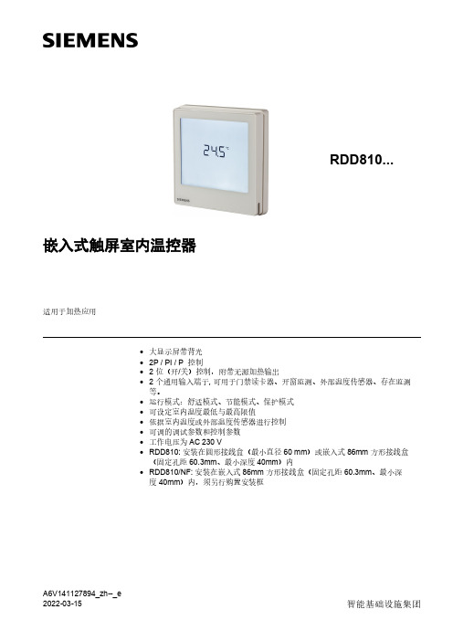
嵌入式触屏室内温控器适用于加热应用•大显示屏带背光•2P / PI / P 控制• 2 位(开/关)控制,附带无源加热输出• 2 个通用输入端子, 可用于门禁读卡器、开窗监测、外部温度传感器、存在监测等。
•运行模式:舒适模式、节能模式、保护模式•可设定室内温度最低与最高限值•依据室内温度或外部温度传感器进行控制•可调的调试参数和控制参数•工作电压为 AC 230 V•RDD810: 安装在圆形接线盒(最小直径 60 mm)或嵌入式 86mm 方形接线盒(固定孔距 60.3mm、最小深度 40mm)内•RDD810/NF: 安装在嵌入式 86mm 方形接线盒(固定孔距 60.3mm、最小深度 40mm)内,须另行购置安装框A6V141127894_zh--_e用途加热系统中的室温控制:典型应用:•公寓•商业建筑•学校下列设备的控制:•电热阀或区域阀•燃气或燃油锅炉•泵•地板采暖功能•通过内置温度传感器或室外温度传感器控制室温•触屏选择运行模式•舒适模式延时扩展•显示当前室内温度或室内温度设定值(︒C / ︒F)•室内温度的最低与最高设定限值•按键锁定功能:解锁、全部锁定和设定值• 2 个多功能输入端子,可选连接以下设备:−外部温度/回风温度传感器−开窗监测−故障输入−监测温度传感器或开关状态的输入−存在监测•地板采暖的供热温度限值•出厂设置重新加载功能可恢复因调试而更改的控制参数•通过 HMI 的向导功能简化调试配置注意:温控器的功能描述请参见用户手册 P3174。
应用温控器支持加热应用:•热循环地板采暖•散热器•壁挂式锅炉2 / 18室内温控器控制散热器阀门室内温控器控制地板采暖阀门室内温控器直接控制燃气壁挂式锅炉室内温控器直接控制燃气落地式锅炉室内温控器直接控制热泵(手动混合阀预控制)室内温控器直接控制热循环地板采暖系统F1 热复位限温温控器F2 安全限值温控器M1 循环泵N1 室内温控器V1 二通阀V2 通过手动调节混合三通阀V3 电磁阀3 / 182)不包括安装框(ARG800.1),须另行订购,参见“附件”3)无需安装框订购•订购时,请指明产品型号、库存编号及产品名称。
西门子SIPART PS100型号阀门控制说明书

/sipartps100Positioners are essential to the smooth and reliable operation of your process.They play a vital role in ensuring the best possible performance throughout your plant. A great example is our new electropneumatic positioner, the SIPART PS100. Its ease and speed of initialization make it a winner for valve manufacturers, the chemical industry, the energy sector, and many other fields. Special benefits of the SIPART PS100 includerobust construction and ease of operation. »Device automatically adjusts to the connected valveAnimated video on user-friendliness»Maximum performance for every applicationReady for tough process conditions »Completely enclosed design »Two enclosure versions–Aluminum – resistant to mechanical influences –Polycarbonate – with a clear view of the screenNon-corrosive sound absorber»PcAiPublished by Siemens AGDigital Industries Process AutomationÖstliche Rheinbrückenstr. 50 76187 Karlsruhe, GermanyFor the U.S. published by Siemens Industry Inc.100 Technology Drive Alpharetta, GA 30005 United StatesArticle No.: DIPA-B10208-00-7600 Dispo 27900 WS 04210.0 © Siemens 2021Subject to changes and errors. The information provided in this brochure contains descriptions or performance characteristics which, in case of actual use, do not always apply as described or which may change as a result of further development of the products. The desired performance characteristics are only binding if expressly agreed in the contract. Availability and technical specifications are subject to change without notice.All product designations may be trademarks or product names of Siemens AG or supplier companies, the use of which by third parties for their own purposes may violate the rights of the owners.https:///sipartps100https:///mobileiqSITRANS mobile IQ app Smart app that establishes a connection to Bluetooth® enabled SIPART PS100。
西门子 风机盘管温控器 说明书
背
光
间/间 程周程 序末序
时
式度 自传 动感 转器
间
换输
程
入
序
电源
RAA10
●
●
2P
●
AC24..250V
RAA20
●
●
2P
RAA30
●
●
2P
RAA40
●
2P ●
RAA40.2
● 2P ●
RDD10 ●
2P
●
●
RDD10.1 ●
2P
●
●
●
AC24..250V
●
AC24..250V
●
AC24..250V
●
●
●
●1)
●
●1)
●
●
●
●
●
●
●
●
●
●
●
●
●
●
●
●
●
●
●
●
●
●
●
●
●
AC24…250V AC24…250V AC24…250V AC24…250V AC24…250V AC24…250V AC24…250V
RCC10
●●●●
2P
●
●
●
●
●
● ● ● AC230V
RCC20
●
●●
2P
●
●
●
●
●
● ● ● AC230V
◆ 流量
◆ 空气质量
◆ P或PI控制 ◆ 各种辅助控制功能可选
RWD68
◆ 多样输入可选(有源/无源)
◆ 操作简单且有大型清晰的LCD显示,易于控制
西门子能源与自动化SIPART PS2控制阀位置器安装说明说明书

KIT INSTALLATION INSTRUCTION SiemensEnergy & AutomationKIT PN - TGX:16152-540 15900-734Rev 1July 2006MOUNTING THE SIPART PS2 VALVE POSITIONER ON ACOPES 60-160, 0.75 STEM, VALVE ACTUATORThis publication provides installation instructions to mount a Siemens SIPART ® PS2 valvepositioner to an above Copes valve actuator and to install the mechanical feedback linkage. Atypical installation is shown below.15900-734PARTS, KIT TGX:16152-540Description QuantityMounting Bracket 1Stem Block 1Spacer 1J-Bracket 15/16-18 x 3/4" Hex Head Screw 25/16-18 x 2.00" Hex Head Screw 25/16" Split Lockwasher65/16" Flat Washer 63/8-16 X 2.75" Socket Head Screw 2M8 x 16 Hex Head DIN933-A2 23/8" Split Lockwasher 2Other Kits: Linear Feedback Kit, part number 6DR4004-8VLINSTALLATIONRefer to the following procedure and to the positioner and actuator installation instructions while performing the installation. The current revision of the positioner instruction is available at theSiemens Internet site. See Contact Information later in this Instruction for the URL.Before beginning the installation, note the following cautions.Do not apply supply pressure to the actuator or the valve positioner during the installation process. Applying supply pressure before the equipment is properly mounted couldcause unexpected movement that could lead to personalinjury or equipment damage.Do not exceed the maximum actuator and valve positionerair pressures stated in the manufacturer’s literature. Exceeding these ratings could cause personal injury or equipment damage.1. From the TGX:16152-540 kit, get the stem block and two 3/8-16 x2.75" socket head screwsand two 3/8 lockwashers. Refer to the figure on page 1 and remove from the stem couplingtwo 3/8" screws in the locations shown for installation of the stem block. Fasten the stemblock to the actuator stem coupling using the 2.75" socket head screws from the kit.2. From the same kit, get the J-bracket and two 5/16-18 x 3/4" hex head screws and 5/16 flatwashers and lockwashers. Fasten the J-bracket to the stem block.3. From the 6DR4004-8VL kit, get two M6 hex head screws and lockwashers, two V-blocks,and the U-channel. Assemble to the J-bracket as shown on page 1.4. From the same kit, get the feedback arm, feedback pin, and a nut and lockwasher to mountthe pin. Fasten the feedback pin to the feedback arm. Tighten the hardware just enough tohold the pin in place.5. Fasten the feedback arm to the PS2 input shaft as shown. Position the pin such that itsdistance from the PS2 shaft is approximately 70%-100% of the stroke (60-90 degreesrotation). Set the PS2’s gear switch to the “90” position.15900-734 6. From the TGX:16152-540 kit, get the mounting plate, spacer, two 5/16-18 x 2.00" hex headscrews and 5/16 washers and lockwashers. Fasten the mounting bracket and spacer to theactuator frame using the 5/16hardware.7. From the same kit, get two M8 screws and 5/16 flat washers and split lockwashers.8. Read the “Important” note below and then fasten the PS2 to the mounting bracket using theabove M8 and 5/16 hardware, while engaging the feedback pin in the U-channel. Slide themounting bracket along its slotted holes until the feedback arm is approximatelyperpendicular to the valve stem at the 50% stroke position. The feedback pin must movefreely inside the U-channel throughout the actuator stroke.IMPORTANTWhile attaching the positioner to the mounting bracket, be sure thefeedback pin is inserted into the U-channel. The spring in the feedback pinshould be compressed approximately 3/16" to 1/4" (4.5mm to 6.5mm).9. Tighten all hardware.10. Read the “Cautions” on page 2 and then apply the appropriate air pressures to fully strokethe valve. Exercise the positioner/actuator assembly to ensure that:•The feedback linkage does not prevent the valve from fully stroking.•The locator pin moves freely within the U-channel for the entire valve stroke. Adjustthe pin and U-channel positions as necessary.•All linkage hardware is secure.11. Once the feedback arm moves freely for the entire stroke, make electrical and pneumaticconnections and proceed to the PS2 setup instruction found within the PS2 manual.CONTACT INFORMATIONFor Product Support in the U.S.A.Technical SupportTelephone +1 800 569 2132, option 2 for Siemens and Moore Products Co. brandinstrumentsFax +1 215 646 3547E-mail **********************.comHours of Operation 8 a.m. to 4:45 p.m. eastern time, Monday through Friday (except holidays)TechnicalPublicationsin PDF /ia; under Customer Support Process Instrumentation, click on Documentation & Support LinksPublic Internet Site /iaRepair Service +1 215 646 7400 extension 3187For Product Support Outside of the U.S.A.Visit the Siemens public Internet site (see the above table for the URL), locate “Customer Support Process Instrumentation,” and click on the Contact Tech Support link to access the Global Support link. SIPART is a trademark of Siemens Energy & Automation, Inc. Other trademarks are the property of their respective owners. All product designations may be trademarks or product names of Siemens Energy & Automation, Inc. or other supplier companies whose use by third parties for their own purposes could violate the rights of the owners.Siemens Energy & Automation, Inc. assumes no liability for errors or omissions in this document or for the application and use of information in this document. The information herein is subject to change without notice.Procedures in this document have been reviewed for compliance with applicable approval agency requirements and are considered sound practice. Neither Siemens Energy & Automation, Inc. nor these agencies are responsible for repairs made by the user.。
加温控器西门子控制器说明书

华特牌高性能二氧化氯控制器利用说明书山大华特科技股分有限公司环保分公司目录概述 (2)注意事项 (2)原理框图 (3)性能指标 (4)前面板显示 (5)电气接线 (8)功能说明 (8)异样现象及其处置 (9)概述PLC控制器是专为华特牌二氧化氯发生器自动控制而开发的高新技术产品。
作为控制其核心的PLC是一种新型的通用自动控制装置,功能壮大。
显示系统为外观精美的工业人机界面,可通过按键灵活实现各类操作。
各收集点温度控制自动进行,从PT100铂热电阻输入的温度信号进入温度控制器,经模拟量输入通道收集,与温度设定值进行比较,运算(PID方式,模糊计算),来控制加热输出(智能调压模块)。
通过对计量泵频率的控制实现整个余氯控制进程。
从余氯传感器输入的4~20mA的测量信号,经模拟量输入通道收集,与余氯设定值进行比较,运算(PID方式,模糊计算),(或通过余氯、流量信号复合环)来控制频率输出。
温度控制、余氯控制具有测量精准,抗干扰能力强,靠得住性高等特点。
本产品同时具有缺料报警保护、欠水压报警保护、缺水报警保护、温度传感器短路、断路保护及超温保护等功能。
控制器具有标准通信接口,符合多种通信规约。
该产品将传统的继电器控制技术、运算机技术和通信技术融为一体,自动化程度高,运行更靠得住,动作迅速,显示更直观、生动。
注意事项本产品为电子产品请务必注意以下事项:✧仪表供电为避免仪表损坏或失效,请利用额定电压供电。
为避免触电,所有接线工作完成后方能接通电源。
✧禁止在易燃气体周围利用为防火、防爆或仪表损坏,禁止在易燃、易爆气体,排放蒸汽的场所利用。
✧严禁触及仪表内部为避免触电或事故,严禁触及仪表内部,发生质量问题请与山东华特公司联系。
只有华特公司服务人员能够检查内部线路或改换部件。
✧接地请利用至少2mm2(AWG14)作为接地线,注意接地线不可与电源回路零线相连。
保养断电后方可清洗仪表面板,而且严禁直接用水清洗。
清除显示器上污渍请用软布或棉纸,禁止用硬物擦拭、触及或操作,不然会损坏或划伤界面。
温控阀使用手册

工达科技
产品使用手册
济南工达捷能科技发展有限公司
(二零一一年第八版) ( 提示:请妥善保管本手册,以备急需,遗失不补!)
前言
尊敬的客户: 您好,感谢您选用济南工达捷能科技发展有限公司为您提供的温控阀系列产品。 我公司经德国SIEMENS楼宇科技公司正式授权代理,并被SIEMENS公司评为优秀
3、 工达公司不可能强调到所有潜在危险的情形。因而,用户在使用时,除严格遵守 本《手册》要求外,务请参考国内相关或近似标准的要求使用,不同标准之间有 冲突时,请参考较高级要求之标准。
4、 本《使用手册》中所提及产品及使用说明是专门针对于暖通空调设备而言的,若 用于其它工况,建议由专业人员根据工艺要求进行控制逻辑分析,或与我公司经 销商联系,我们的工程技术人员一定会竭尽全力给您满意的答复和建议。
! 警告:切不可先拧紧背死 4. 旋转执行器手动旋钮(SQX、SKD系列)或手动摇柄(SKB、SKC系列)将执行器连
接凹槽与阀杆顶部凹槽对正(注意:SKB、SKC系列要先将执行器下部连接内螺 纹活节拆下,并将连接活节套于阀杆上。) 5. SQX、SKD执行器连接: 用内六方紧固连接螺丝,直至执行器与阀杆紧密连接。 ! 注意:①两侧螺丝均匀用力拧紧,不可拧偏,否则将产生扭力,可能导致阀
第 10 页
执行器与阀体的安装步骤(以SKB/C系列的执行器与阀体的连接举例): 步骤一:
步骤二:
步骤三:
! 警告:①整个安装过程中切勿碰伤阀杆 ②SKB、SKC执行器与阀杆连接时 ,连接内螺纹连母一定要与执行器丝同 步相扣,若错位,将导致滑丝,且不可修复。
! 注意:①一定要将手动操作恢复至自动。否则,执行器通电后不动作或造成损坏。 ②系统若进行打压试验之前,一定要将执行器装于阀体上。并使阀体处于手 动开启状态,待试验完毕,务必将阀杆提起,恢复至自动状态。 第 11 页
- 1、下载文档前请自行甄别文档内容的完整性,平台不提供额外的编辑、内容补充、找答案等附加服务。
- 2、"仅部分预览"的文档,不可在线预览部分如存在完整性等问题,可反馈申请退款(可完整预览的文档不适用该条件!)。
- 3、如文档侵犯您的权益,请联系客服反馈,我们会尽快为您处理(人工客服工作时间:9:00-18:30)。
西门子自动化有限公司(内部使用,随机资料)
电
动
阀
门
安
装
使
用
说
明
书
JXWK-01
目录
1、产品介绍 (02)
2、产品特点 (02)
3、阀门技术参数 (02)
4、注意事项 (02)
5、故障排除 (03)
6、现场安装示意及说明 (04)
7、阀门安装 (06)
8、阀门外形尺寸 (06)
9、阀门与执行器连接
(1)SKD62 (07)
(2)SKB/SKC62 (08)
10、控制箱的安装 (10)
11、传感器的安装 (11)
12、内部跳线图 (12)
13、接线图
(1)RWD68温度控制 (13)
(2)RWD62温度控制 (14)
(3)RWD68/62压力、压差控制 (15)
(4)超温切断控制 (16)
14、调试说明 (17)
15、售后服务 (18)
16、质量反馈卡 (19)
- 1 -
一、产品介绍
根据现场情况的不同,选用电动两通阀,能够满足空调制冷、换热供暖、通风等控制系统的需要,达到调节温度、压力、湿度及流量的目的。
也广泛适用于石油、化工、冶金、纺织、印染等工业现场的自动控制。
二、产品特点
电动两通阀采用进口执行器、控制器、传感器,阀门采用平衡式单阀座结构,能够抵消阀门内部高压降产生的推力,有效解决高压现场关断力的问题,降低了执行器的负荷,延长了机器寿命。
电动执行器标准配置采用西门子公司产品,并根据国内蒸汽现场的实际情况作了传热隔离措施,更加适应国内现场使用条件。
三、两通阀门技术参数
四、注意事项
◆杂物(焊渣等)进入温控阀,将造成机器不能正常工作,引起出口
温度升高,并会造成严重损坏。
◆推荐在温控阀前加装过滤器,在安装前就冲洗好管道。
◆旁路系统中的阀门必须严密,否则旁通的漏气将造成温度升高,并
严重损坏温控器。
- 2 -
◆开式系统:所有形式的温控阀,无论是进口还是国产,都不能够做
到完全密封,有一定的泄漏量,所以不推荐使用到24小时直供开式生活水系统,例如不循环的桑拿浴现场等。
如果在该类现场使用,务必增加蓄水缓冲,将系统改为循环,保护切断等措施(参看接线图4)。
◆近年来一些新产品的使用现场,目前国家、行业均没有规范,设计
时请考虑:在有PPR、地温采暖或类似产品使用现场中,推荐增加保护措施,主要是管路高温切断(参看接线图4)。
五、故障排除
系统部分:
1.检查旁通是否关闭:如果旁通没有关闭,则应关闭旁通。
2.检查疏水装置是否故障;
3.传感器插入位置是否避开死水区,或插入位置太少;
设备部分:
1、检查线路,确定接线无误,信号输入输出、供电正常;
2、检查控制器曲线、设定、显示是否正常;
3、检查执行器、连接杆均良好固定(注意受力时的表现),并确定执
行器的工作状态是否在自动状态(SKD SKB SKC)如果执行器的红色状态标志露在外面,则是手动状态, 应停电后手拧返回自动状态(第6页图2)
4、排除以上原因后,阀门仍然有泄漏现象,可在厂家的指导下拆开
阀门检查是否有管路异物(特别是新管路)
5、控制器不显示:检查(接线图)24VAC前后端的电压,判断是否是
变压器故障。
六、现场安装示意及说明
- 3 -
- 4 -
说明:1、此图为安装示意图,换热器可以是板式、容积式、双纹管式、浮动盘管等。
2、电动调节阀一般安装在一次热媒管道上,高温水热
媒现场可以安装在回水管路上。
3、传感器有效期长度为110mm,应垂直插入水流通畅
且流速平稳的出水直管段上,如果出水直管段直径
不够,就安装在离换热器较近的出水弯管处,详情
见上图
4、图中过滤器、截止阀及旁通原则上要求安装。
5、控制箱就近挂在墙壁上,且防雨防潮;接入电源为
220V。
- 5 -
七、阀门安装
阀门与执行器可在现场方便地安装,无需特殊工具及其调整
安装方向
流向安装阀门时请注意阀体上方向
使用安装前应该吹尽管路中的杂物,并在阀门前安装过滤器,以免杂物引起故障。
八、两通阀门参数表PN16(mm)
DN A D D1 螺栓(n-m)
25 160 115 85 4 M12
32 180 135 100 4 M16
40 200 145 110 4 M16
50 230 160 125 4 M16
65 290 180 145 4 M16
80 310 195 160 8 M16
100 350 215 180 8 M16
125 400 245 210 8 M16
150 480 280 240 8 M20
200 500 335 295 12 M20
250 620 405 355 12 M22
- 6 -
九、与执行器的连接方法
1.SKD62执行器
SKD32… AC230V ±15%
SKD62… AC 24V ±20%
50HZ 60HZ
IP54 ICE529
图 1
图2
- 7 -
2.SKC62/SKB62执行器
SKD32… AC230V ±15%
SKD62… AC 24V ±20%
50HZ 60HZ
IP54 ICE529
- 8 -
- 9 -
- 10 -
十、控制箱安装 (mm )
1.安装场所
本控制器为电子控制装置,要充分考虑其设置环境。
1.1避免安装在高温、多湿、阳光直射和灰尘、金属粉尘较多的场所。
1.2适用环境温度范围:-10~+50℃;
1.3适用环境湿度范围:90%以下(无水珠凝结); 1.4请安装在没有震动的地方。
1.5无电磁干扰源。
2.注意事项
2.1清楚接线图后进行配线:输入电源如误接到其他端子,设备不能正常运行,并可能烧毁设备; 2.2控制信号要注意下列各项: 2.2.1控制继电器要使用微小电流型。
2.2.2远距离控制回路的配线尽量采用屏蔽绞线,并注意与交流电源
线、大功率用电设备拉开距离。
产品规格:355×253×71 输入电源:AC220V ±5%
50/60HZ
输入信号:N i 1000 输出信号:DC 0-10V 执行标准:GB7251.1-1997
防护等级:IP45
2.2.3注意用电安装符合GB7251-1997规范;
2.2.4用电安全:壳体接地。
十一、传感器安装
十二、内部跳线图
1.现场安装时可现将套筒取
下,将套筒固定在管路上,
保证套筒大部分浸入出水
中。
2.将传感器插入套筒中,保
证卡箍卡紧套筒。
3.接线时注意传感器有极性
(B、M)勿使与控制箱内
接线相反。
- 11 -
- 12 -
十三、接线图:
(接线图一)
- 13 -
(接线图二)
- 14 -
(接线图三)
- 15 -
(接线图四)
- 16 -
十四、调试说明
1、检查控制箱、执行器、传感器接线是否有误(对照接线图进行正确
连接);
2、检查执行器一定位于自动控制位置;
3、通电5秒钟后,机器显示正常。
按动加键,依次为实时温度、设定
温度;
4、设定界面介绍:同时按动加减号5秒钟后,开始进入。
需要修改,
只需要进入相应界面,按动“SEL”键,需要设定的数值开始闪动,修改即可。
修改完毕后,按动“SEL”键确认。
十五.售后服务
1、本控制装置保修期为购买后的12个月
由于以下原因引发的故障,即使在保修期内,亦是属于有偿修理:
●不正确的操作或未经允许自行修理及改造所引起问题;
●超出规范使用要求造成的问题;.
●购买后跌损或野蛮装运造成的损坏。
●因在不符合本使用技术手册要求的环境下使用所引起的器件或故
障。
●由于地震、火灾、风水灾害、雷击、异常电压或其他自然灾害或与
灾害相伴的原因所引起的故障。
2、关于用户使用须知
对于违背本使用说明使用本公司的电控设备而产生的诱发的责任本公司不能承担。
对于本公司的电控设备故障所致贵方受到的损失或波及性、继发性损害,本公司不负责赔偿。
3、售后服务
根据现场情况,请按照以下内容尽可能的告知我们。
我们将最快的、最好的服务来回报用户。
- 18 -
- 19 -
设备质量反馈卡
尊敬的顾客:
感谢您选用我公司的产品。
我公司本着以质量卓越为最终目标,为了更好的为您服务,
满足您的需要,我们真诚地希望您能把该设备在使用过程中出现的问题以及您的要求或意见告诉我们。
请填写好背面的质量反馈卡,按下面的联系方式传真我公司。
谢谢合作!
西门子自动化有限公司
沿
线
裁
下。