DELl 390台式机用户手册
戴尔电脑说明书.pdf_1700484210.7766528
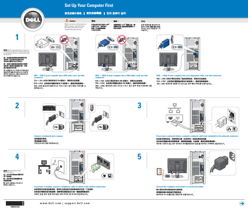
If you have a network device, connect a network cable (not included) to the network connector.
5
Connect the computer and monitor to electrical outlets.
May 2005
Connect other devices according to their documentation.
front/back USB 2.0 connectors
integrated sound optional sound card
Support and educational tools are available on the Dell Support website at .
For additional information about your computer, click the Start button and click Help and Support.
headphone connector
ห้องสมุดไป่ตู้
optional floppy drive or optional Media Card Reader
Help and Support
See your Owner's Manual for additional setup instructions, including how to connect a printer.
VGA → VGA: If your computer has a VGA video card, use that connector.
VGA → VGA: If your computer has only integrated video, use that connector.
戴尔电脑产品用户手册说明书

291st Revised Page 1CANCELS 290th Revised Page 1(This page filed under Transmittal No. 311 ) ACCESS SERVICERATES, RULES AND CHARGESTitle Page and Pages 1 to 22-45, inclusive of this tariff are effective as of the date shown. Original and revised pages as named below and Supplement No. 7 contains all changes from the original tariff that are in effect on the date hereof.CHECK SHEETNumber of Number of Revision Revision Except as Except asPageIndicated Page IndicatedTitle 4th 22.3 6th 1 291st*22.4 7th 1.1 26th 23O riginal 1.2 122nd* 24 O riginal 1.2.1 2nd 25 1st 1.3 11th 26 1st 1.4 37th 27O riginal 1.5 70th*28 1st 1.5.1 15th 29 1st 1.6 28th 30 2nd 1.7 12th 31 1st 1.7.1 3rd 1-1O riginal 1.8 18th 1-2 3rd 1.9 62nd 2-1 2nd 1.10 17th 2-2 2nd 1.11 26th 2-3 3rd 1.12 36th 2-4 5th 1.13 22nd 2-5 3rd 1.14 15th 2-5.1 1st 1.15 4th 2-6 1st 1.16 1st 2-7Original 2 4th 2-8Original 3 2nd 2-9Original 4 3rd 2-10Original 5 2nd 2-11Original 6 3rd 2-12 1st 7 4th 2-13Original 8 3rd 2-14 6th 9 1st 2-15 5th 10 7th 2-15.1 4th 11 2nd 2-16Original 12 1st 2-17 4th 13 2nd 2-18Original 14 1st 2-19Original 15 3rd 2-20Original 16 5th 2-21Original 17 6th 2-22Original 18 2nd 2-23Original 19 5th 2-24Original 20 2nd 2-25Original 21 6th 2-26 1st 22 7th 2-27Original 22.1 2nd 2-28Original 22.2 44th 2-29O riginal* New or Revised PageIssuing Officer: Kristen E. Shore, Assistant Vice President - RegulatoryRATES, RULES AND CHARGESCHECK SHEET (Cont’d)Number of Number ofRevision RevisionExcept as Except asPage Indicated Page Indicated3-13 2nd 5-11.2Original3-14 2nd 5-11.3Original3-15 2nd 5-12 1st3-16 1st 5-13 4th3-17 1st 5-14 4th3-18 1st 5-14.1Original3-19 Original 5-15 7th3-20 Original 5-16 3rd3-21 1st 5-17 11th3-22 1st 5-17.1 8th3-23 1st 5-17.1.1 6th3-24 2nd 5-17.2 7th3-25 1st 5-18 6th3-26 2nd 5-19 6th3-27 2nd 5-19.15th3-28 1st 5-19.2 4th3-29 2nd 5-19.3 4th3-30 1st 5-19.4 4th4-1 2nd 5-19.54th4-2 2nd 5-19.6 4th4-3 Original 5-19.74th4-4 4th 5-20 6th4-5 2nd 5-21Original4-6 1st 5-22Original4-7 1st 5-23Original4-8 2nd 5-24Original4th 5-25Original 4-8.14-9 67th*5-26 1st4-10 29th*5-27Original4-10.1 7th5-28Original4-11 72nd*6-1 3rd5-1 5th 6-2 1st5-2 2nd 6-31st5-3 7th 6-4 1st5-3.1 6th 6-5Original5-3.2 3rd 6-6Original5-3.3 3rd 6-7Original5-3.4 7th 6-8Original5-4 1st 6-9 1st5-5 1st 6-10 1st3rd 6-11Original 5-62nd 6-12Original 5-75-8 Original 6-13Original1st 6-14Original 5-93rd 6-15Original 5-105-11 2nd 6-16Original5-11.11st* New or Revised Page(This page filed under Transmittal No. 311 )ACCESS SERVICERATES, RULES AND CHARGESCHECK SHEET (Cont’d)Number of Revision Number of Revision Page Except as Indicated Page Except as Indicated7-26 Original 7-812nd 7-27 3rd 7-81.15th7-28 1st 7-81.24th7-29 Original 7-81.32nd 7-30 Original 7-81.49th 7-31 Original 7-81.56th7-32 Original 7-81.64th 7-33 3rd 7-81.6.1Original7-33.1 2nd 7-81.75th7-34 1st 7-81.8Original7-35 Original 7-8227th 7-36 Original 7-8311th 7-37 Original 7-8419th 7-38 Original 7-84.19th* 7-39 1st 7-852nd7-40 Original 7-85.11st 7-41 2nd 7-85.24th7-42 2nd 7-865th7-43 Original 7-875th 7-44 1st 7-87.15th7-45 Original 7-87.25th7-46 Original 7-87.34th 7-47 Original 7-87.44th 7-48 Original 7-882nd 7-49 2nd 7-892nd7-50 Original 7-903rd 7-51 Original 7-913rd 7-52 1st 7-91.15th7-53 1st 7-91.25th7-54 Original 7-91.2.12nd7-55 Original 7-91.32nd 7-56 10th 7-91.42nd7-57 Original 7-91.52nd 7-58 1st 7-91.62nd7-59 Original 7-91.72nd 7-60 Original 7-91.82nd 7-61 2nd 7-91.92nd7-62 3rd 7-91.102nd7-63 1st 7-926th7-64 3rd 7-935th7-65 1st 7-93.13rd7-66 5th 7-94Original7-66.1 2nd 8-13rd7-67 1st 8-24th7-68 Original 8-35th 7-69 3rd 8-3.13rd7-69.1 2nd 8-43rd7-69.2 2nd 8-53rd7-70 Original 8-62nd 7-71 Original 8-74th 7-72 Original 8-84th 7-73 10th 8-94th7-74 Original 8-104th 7-75 1st 8-114th7-76 Original 8-122nd 7-77 1st 8-132nd7-78 1st 8-142nd7-78.1 Original 8-155th 7-79 6th 8-163rd7-79.1 Original 8-175th 7-80 4th 8-184th8-193rd* New or Revised(This page filed under Transmittal No. 311 ) ACCESS SERVICE4. End User Access Service (Cont’d)4.6 Rate Regulations (Cont’d) 4.6.1 End User Common Line Rate Elements (Cont’d) (H) Federal Universal Service Fund (FUSF) Surcharge (Cont’d)(3) Other Non-recurring FUSF SurchargesIn addition to the applicable charges above, when a customer is assessed interstate end user chargesidentified in the table below, a FUSF Surcharge will also apply as set forth in Section 4.7(I) following. For example, customers assessed the PIC changecharge as specified in Section 13.3.3.(b)(5)(e)(ii) will also be assessed the PIC change FUSF Surcharge as set forth in Section 4.7(I) following.To the extent an IC is assessed a PIC Change Charge, the Non-recurring FUSF Surcharge will also apply to the IC.(4) Other FUSF SurchargesA percentage surcharge factor is assessed monthly on billed recurring and non-recurring charges of end user services other than surcharges described in Section 4.FUSF Surcharge factor: 0.201Tariff Reference Rate Element13.3.3(A)PIC Change Charge(I)(This page filed under Transmittal No. 311 ) ACCESS SERVICE4. End User Access Service (Cont’d)4.7 Rates and ChargesThe rates for End User Access are:(A) End User Common Line (EUCL) - Primary Residence SubscriberUSOC Rates Per Month - Individual lineor trunk, each 9ZEU1 $4.72(B) End User Common Line (EUCL) Non-Primary Residence Subscriber USOC Rates Per Month - Individual lineor trunk, each 9ZEU2 $4.72- BRI ISDN Facility, each wire pair 9ZEU5 4.72(C) End User Common Line (EUCL) -Single Line BusinessUSOC Rates Per Month - Individual lineor trunk, each 9ZEU3 $4.72(D) End User Common Line (EUCL) - Multiline Business SubscriberUSOC Rates Per Month - Individual lineor trunk, each 9ZEU4 $4.72- Public Telephone Access line, each 9ZEU4 4.72 - PRI ISDN Facility, each 9ZEU6 23.60(E) End User Common Line (EUCL) - Centrex CO and CO-like (Installedor on order prior to July 28, 1983)USOC Rates Per Month- Individual lineor trunk, each 9ZEU4 4.72(R) (R) (R) (R) (R) (R) (R) (R)ACCESS SERVICE4. End User Access Service (Cont’d)4.7 Rates and Charges (Cont’d)(G) Presubscribed Interexchange Carrier ChargesUSOC Rate Per Month(A) Multi-Line Business 9PCC4 0.00(B)ISDN-PRI-per service 9PCC6 0.00(C) Centrex CO andCentrexCO-Like-Nine or more lines, per line 9PCC7 0.00-Eight or less lines, per service 9PCC9 0.00(H) End User Port Charge USOC Rate Per Month(1) BRI ISDN Port- Per Port 9SDN1 $3.90(2) PRI ISDN Port- Per Port 9SDN2 $36.29(I)Basic FUSF Surcharge:USOC Rate Per Month(1) Residential 9PZRS $ 0.94(2) Single-Line Business 9PZBU $ 0.94(3) ISDN BRI 9PZL1 $ 1.73(4) Multiline Business 9PZLM $ 2.34(5) PRI ISDN 9PZP1 $18.99(6) PBX 9PZPX $ 2.34(7) Centrex CO and CO-Like 9PZCX $ 0.26(8) Other FUSF Surcharges USOC Rate Per Occurrence PIC Change Charge(a) Per Manual Change 9PZGM $ 0.78(b) Per Mechanized Change 9PZGE $ 0.32 (I) (I) (I) (I) (I) (I) (I) (I) (I)(This page filed under Transmittal No. 311 )(This page filed under Transmittal No. 311 ) ACCESS SERVICE7. Special Access Service (Cont'd)7.11 High Capacity Service 7.11.5 Rates and Charges General Description (Cont'd) 7.11.5.3 Rates and Charges (Cont'd)(F) DS1 Term Payment PlanRates and Charges for the DS1 Term Payment Plan (1)(1)Channel Termination - Per Point of TerminationUSOC1 Year2 Year3 Year 5 Year 7 Year TMECS $122.50 $120.00 $115.00 $104.00(R) $98.50(2) Channel Mileage- Channel Mileage Termination (per termination)- Channel Mileage Facility (per mile)USOC 1 Year 2 Year 3 Year 5 Year 7 Year 1L5XX$ 9.00$ 9.00$ 8.70$ 8.40$ 8.25(3) Central Office Multiplexing DS1 to DS0 voice/digital-Per arrangementUSOC1 Year2 Year3 Year 5 Year 7 Year MQ1, MQ1++,QMU, QMUA1, QMU++$180.00 $170.00 $170.00 $ 160.00 $150.00(4) Collocation Transport-Channel Mileage - FixedUSOC 1 Year 2 Year 3 Year 5 Year 7 Year 1H48S$ 51.00 $ 45.00 $ 40.00 $ 35.00 $ 32.50– Per Mile USOC 1 Year2 Year3 Year 5 Year 7 Year 1H48S$ 9.25$ 9.00$ 8.75$ 8.50$ 8.25(5) Nonrecurring Charges-One Time Charges- Per point of channel termination USOC DESCRIPTION RATE TMECS Channel Termination NonrecurringCharge$ 900.001H48S Collocation Transport NonrecurringChargeNOTE: Channel Termination Nonrecurring Charges and Collocation Transport Nonrecurring Chargesare waived on new installations of DS1 High Capacity Service with a 2, 3, 5, or 7 year DS1 TPP.(1) Effective on September 13, 2017, DS1 TPP 5- and 7-year Payment Plans are no longer available,including for any otherwise available conversions. Circuits already subject to a DS1 TPP 5- or 7-year Payment Plan, as of September 13, 2017, will continue to be provided under the then-current DS1 TPP 5- and 7-year Payment Plan term for the remainder of that term.USOC 1 Year 2 Year 3 Year 5 Year 7 Year 1L5XX$ 51.00$ 45.00$ 40.00$ 35.00$ 32.50。
戴尔 OptiPlex 390 技术指南说明书

DELLTM390TABLE OF CONTENTSOVERVIEWMini Tower Computer (MT) View 3-4 Desktop Computer (DT) View 5-6 Small Form Factor Computer (SFF) View 7-8Operating System, Chipset 9 Processor 10 Memory 11 Hard Drives, Removable Storage, System Expansion Slots 12 Graphics/Video Controller, External Ports/Connectors 13 Communications—Network Adapter (NIC), Wireless 14 Audio and Speakers, Keyboard and Mouse 14 Security, Software, Environmental, All-in-One Stands & Mounts, Service and Support 15System Dimensions (Physical) 16 System Expansion Slots 16 System Level Environmental and Operating Conditions 17 Power 18-19 Audio 20 Communications 20-25 Graphics/Video Controller 26-27 Hard Drives 28-31 Optical Drive 32-33 Media Card Reader 34 BIOS Defaults 35 Chassis Enclosure and Ventilation Requirements 36 Environmental Attributes 37 Acoustic Noise Emission Information 38-40MINI TOWER COMPUTER (MT) VIEW23 456 789110 11 12131415 161 2 3 456789MT System Board ComponentsDESKTOP COMPUTER (DT) VIEW1 2 3 4 5 6 7 8 9 10 1112 13 14 151 2 3 45678 9DT System Board ComponentsSMALL FORM FACTOR COMPUTER (SFF) VIEW12 34 5 67 8 9 10 11 14 1512 135 6 7 31824SFF System Board ComponentsMARKETING SYSTEM CONFIGURATIONSNO TE: O f fe rin gs ma y v a ry by c ou ntry.Fo r mo r e i nf o rma ti o n re ga rdi ng t he c onfi gu ra ti o n o f y ou r c om pu ter,c lic k Sta r t>H elp a nd Su ppo r t a nd s elec t th e o p ti on to v i ew i n fo rma ti on a bou t you r c o mpu t er.OPERATING SYSTEMCHIPSETPROCESSORNOTE: Global Standard Products (GSP) are a subset of Dell’s relationship products that are managed for availability and sync hro-nized transitions on a worldwide basis. They ensure the same platform is available for purchase globally. This allows customers to reduce the number of configurations managed on a worldwide basis, thereby reducing their costs. They also enable companies to implement global IT standards by locking in specific product configurations worldwide. The following GSP processors identi-fied below will be made available to Dell customers.NOTE: Processor numbers are not a measure of performance. Processor availability subject to change and may vary by region/ country.MEMORYNOTE: Memory modules should be installed in pairs of matched memory size, speed, and technology. If the memory modules are not installed in matched pairs, the computer will continue to operate, but with a slight reduction in performance. The entire 8GB memory range is available to 64-bit operating systems.1 The total amount of available memory will be less than 4GB. The amount less depends on the actual system configuration. To fully utilize 4GB or more of memory requires a 64-bit enabled processor and 64-bit operating system.HARD DRIVESREMOVABLE STORAGENOTE: Dell 19 in 1 Media Card Reader (MCR) is supported via a F5 to F3 bay converter on the MT and DT and may require a slim1 For hard drives, GB means 1 billion bytes; actual capacity varies with preloaded material and operating environment and will be less.2 Discs burned with this drive may not be compatible with some existing drives and players; using DVD+R media provides maximum compatibility.3 DVD-ROM drives may have write-capable hardware that has been disabled via firmware modifications.SYSTEM EXPANSION SLOTSNOTE: See Detailed Engineering Specifications for maximum card dimensions.NOTE: Add in card location and priority: PCIe x16: GFX, USB 3.0, Serial, Parallel/Serial, NIC, Wireless; PCIe x1: USB 3.0, Serial,GRAPHICS/VIDEO CONTR OLLERNOTE: MT supports full height (FH) cards and DT and SFF supports low profile (LP) cards.EXTERNAL PORTS/CONNE CTORSNOTE: MT supports full height (FH) cards and DT and SFF supports low profile (LP) cards. See chassis diagrams section for port/ connector locations1This term does not connote an actual operating speed of 1 Gb/sec. For high speed transmission, connection to a Gigabit Ethernet server and network infrastructure is required.COMMUNICATIONS – WIRELESSNOTE: MT supports full height (FH) cards and DT and SFF supports low profile (LP) cards.AUDIO AND SPEAKERSCOMMUNICATIONS - NETWORK ADAPTER (NIC)NOTE: MT supports full height (FH) cards and DT and SFF supports low profile (LP) cards.SECURITYSOFTWAREENVIRONMENTALNOT E:Fo r mo r e d eta i l s o n D el l En vi r o n men ta l fea t ur es, pl ea s e to go to En vi r o n men ta l A t tr i b utes s ec ti o n.See yo ur s pec i fi c r egi o n fo r a v a i l a bi l i ty.ALL-IN-ONE STANDS AN D MOUNTSSERVICE AND SUPPORTNOT E: Fo r mo r e de ta i l s o n D el l Ser vi c e Pl a n s pl ea s e to go to:w w w.del l.c o m/s er vi c e/s er vi c e_pl a n s1 For a copy of our guarantees or limited warranties, please write Dell USA L.P., Attn: Warranties, One Dell Way, Round Rock, TX 78682. For more information, visit /warranty.2 Service may be provided by third-party. Technician will be dispatched if necessary following phone-based troubleshooting. Subject to parts availability, geographical restrictions and terms of service contract. Service timing dependent upon time of day call placed to Dell. U.S. only.DETAILED ENGINEERING SPECIFICATIONSSYSTEM DIMENSIONS (P HYSICAL)NOTE: System Weight and Shipping Weight is based on a typical configuration and may vary based on PC configuration. A typical configuration includes: integrated graphics, one hard drive, one optical drive.SYSTEM EXPANSION SLOTSSYSTEM LEVEL ENVIRONMENTAL AND OPERATING CONDITIONSPOWERNOTE: These form factors utilize a more efficient Active Power Factor Correction (APFC) power supply. Dell recommends only Universal Power Supplies (UPS) based on Sine Wave output for APFC PSUs, not an approximation of a Sine Wave, Square Wave, or quasi-Square Wave. If you have questions, please contact the manufacture to confirm the output type.POWERNOTE: These form factors utilize a more efficient Active Power Factor Correction (APFC) power supply. Dell recommends only Universal Power Supplies (UPS) based on Sine Wave output for APFC PSUs, not an approximation of a Sine Wave, Square Wave, or quasi-Square Wave. If you have questions, please contact the manufacture to confirm the output type.AUDIOCOMMUNICATIONS - NETWORK ADAPTER (NIC)NOTE: MT supports full height (FH) cards and DT and SFF supports low profile (LP) cards.COMMUNICATIONS - NETWORK ADAPTER (NIC) (CONT.)1 This term does not connote an actual operating speed of 1 Gb/sec. For high speed transmission, connection to a Gigabit Ethernet server and network infrastructure is required.COMMUNICATIONS – INTEGRATED LANNOTE: MT supports full height (FH) cards and DT and SFF supports low profile (LP) cards.1 This term does not connote an actual operating speed of 1 Gb/sec. For high speed transmission, connection to a Gigabit Ethernet server and network infrastructure is required.COMMUNICATIONS – INTEGRATED LAN (CONT.)1This term does not connote an actual operating speed of 1 Gb/sec. For high speed transmission, connection to a Gigabit Ethernet server andCOMMUNICATIONS – WIRELESSCOMMUNICATIONS – USB 3.0 ADD-IN CARDNOT E: M T s u p po r ts ful l h e i gh t (FH) c a rds a n d D T a n d S FF s u ppo r ts l o w pr o fi l e (L P) c a r ds.COMMUNICATIONS – SERIAL / PARALLEL PORT PCIE ADD-IN CARD NOT E: M T s u p po r ts ful l h e i gh t (FH) c a r d.COMMUNICATIONS—PS2/SERIAL ADD IN DONGLENOT E: M T s u p po r ts ful l h e i gh t (FH) don gl e a n d D T a n d S FF s u ppo r ts l o w pr o fi l e (L P) do n gl e.GRAPHICS/VIDEO CONTR OLLERNOT E: M T s u p po r ts ful l h e i gh t (FH) c a r ds a n d D T a n d S FF s u ppo r ts l o w pr o fi l e (L P) c a r ds.1 Up to 1.7 GB of system memory may be allocated to support integrated graphics, depending on operating system, system memory size and other factors.2 DVI and VGA can be used concurrently for multi-monitor display in DOS. The DisplayPort controller does not support multi-monitor display inDOSHARD DRIVES11 For hard drives, GB means 1 billion bytes ; actual capacity varies with preloaded material and operating environment and will be less.1For hard drives, GB means 1 billion bytes ; actual capacity varies with preloaded material and operating environment and will be less.1 For hard drives, GB means 1 billion bytes ; actual capacity varies with preloaded material and operating environment and will be less.HARD DRIVES1(CONT.)1 For hard drives, GB means 1 billion bytes ; actual capacity varies with preloaded material and operating environment and will be less.OPTICAL DRIVES1 Discs burned with this drive may not be compatible with some existing drives and players; using DVD+R media provides maximum compatibility.OPTICAL DRIVES (CONT.)MEDIA CARD READER (MCR)NOTE: Dell 19 in 1 Media Card Reader (MCR) is supported via a F5 to F3 bay converter on the MT and DT and may require a slim line optical drive depending on selectable configuration. MCR is not available on the SFF and USFF chassis.BIOS DEFAULTSCHASSIS ENCLOSURE & VENTILATION REQUIREM ENTSENCLOSURE VENTILATIONIf your enclosure has doors, they need to be of a type that allows at least 30% airflow through theenclosure (front and back).ENCLOSURE MINIMUM CLEARANCELeave a 10.2 cm (4 in.) minimum clearance on all vented sides of the computer to permit the airflowrequired for proper ventilation.RECOMMENDED ENCLOSUREDo not install your computer in an enclosure that does not allow airflow. This restricts the airflowand impacts your computer’s performance, possibly causing it to overheat.OPEN DESK MINIMUM CLEARANCEIf your computer is installed in a corner, on a desk, or under a desk, leave at least 5.1 cm (2 in.) clearancefrom the back of the computer to the wall to permit the airflow required for proper ventilation.REGULATORY COMPLIANCE AND ENVIRONMENTALProduct related conformity assessment and regulatory authorizations including Product Safety, Electromagnetic Compatibility (EMC), Ergonomics, and Communication Devices relevant to this product may be viewed at /regulatory_compliance. The Regulatory Datasheet for this product is located at /regulatory_compliance. Details of Dell's environmental stewardship program to conserve product energy consumption, reduce or eliminate materials for disposal, prolong product life span and provide effective and convenient equipment recovery solutions may be viewed at/environment. Product related conformity assessment, regulatory authorizations, and information encompassing Environmental, Energy Consumption, Noise Emissions, Product Materials Information, Packaging, Batteries, and Recycling relevant to this product may be viewed by clicking the Design for Environment link on the webpage.OPTIPLEX 390 MTThe Declared Noise Emission in accordance with ISO 9296 for the Dell OptiPlex 390 MT is as follows:(all values L WAd expressed in bels; 1 bel=10 decibels, re 10-12 Watts)The Declared A-weighted Sound Pressure Level in decibels (re 2x10⁻⁵Pa), at Operator, Bystander, and Desk Side Positions are measured in accordance with ISO 7779 7.6.1, 7.6.2, and C.15.2 and declared in accordance with ISO 9296 for this product is as follows1:1 All tests are conducted according to ISO 7779 and declared according to ISO 9296 except 90% CPU. For this mode, the system CPU was stressed at 90% utilization with no other peripheral device actively seeking. This test mode is not specified in ISO 7779, but was measured using the same microphone distances and measurement techniques defined for the other reported operating modes.OPTIPLEX 390 DTThe Declared Noise Emission in accordance with ISO 9296 for the Dell OptiPlex 390 DT is as follows:(all values L WAd expressed in bels; 1 bel=10 decibels, re 10-12 Watts)The Declared A-weighted Sound Pressure Level in decibels (re 2x10⁻⁵Pa), at Operator, Bystander, and Desk Side Positions are measured in accordance with ISO 7779 7.6.1, 7.6.2, and C.15.2 and declared in accordance with ISO 9296 for this product is as follows1:1 All tests are conducted according to ISO 7779 and declared according to ISO 9296 except 90% CPU. For this mode, the system CPU was stressed at 90% utilization with no other peripheral device actively seeking. This test mode is not specified in ISO 7779, but was measured using the same microphone distances and measurement techniques defined for the other reported operating modes.ACOUSTIC NOISE EMISSION INFORMATIONOPTIPLEX 390 SFFThe Declared Noise Emission in accordance with ISO 9296 for the Dell OptiPlex 390 SFF is as follows:(all values L WAd expressed in bels; 1 bel=10 decibels, re 10-12 Watts)The Declared A-weighted Sound Pressure Level in decibels (re 2x10⁻⁵Pa), at Operator, Bystander, and Desk Side Positions are measured in accordance with ISO 7779 7.6.1, 7.6.2, and C.15.2 and declared in accordance with ISO 9296 for this product is as1 All tests are conducted according to ISO 7779 and declared according to ISO 9296 except 90% CPU. For this mode, the system CPU was stressed at 90% utilization with no other peripheral device actively seeking. This test mode is not specified in ISO 7779, but was measured using the same microphone distances and measurement techniques defined for the other reported operating modes.。
Dell电脑raid设置

Dell 电脑raid 设置高级功能Dell P recision 390工作站用户指南LegacySelect技术控制LegacySelect 技术控制可以基于通用平台、硬盘驱动器映像和帮助桌面程序提供完全使用、 使用传统功能的解决方案。
管理员可以通过系统设置程序、 Dell Op enManage IT Assistant 部分使用或不或Dell 工厂集成服务进行控制。
LegacySelect 使管理员可以通过电子方式激活或取消激活连接器和介质设备(包括串行和并行连接器、软盘驱动器、PCI 插槽和PS/2鼠标)。
取消激活连接器和介质设备后,便可以使用资源。
您必须重新启动计算机才能使更改生效。
USB 连接器、可管理性警报标准格式ASF 是一种DMTF 管理标准,用于规定预操作系统”或无操作系统”的警报技术。
此标准可以在操作系统 处于睡眠状态或系统关机时生成有关潜在安全问题和故障状态的警报。
ASF 是专为替代先前的无操作系统警报技术而设计的。
您的计算机支持以下 ASF 警报:有关D e l l的A S F实现的详细信息,请参阅D e l l支持W e b站点上的A S F用户指南和A S F管理员指南。
Dell OpenMan age IT Assista ntIT Assistant可以配置、管理和监测公司网络上的计算机及其它设备,并可以为配备行业标准管理软件的计算机管理资产、配置、事件(警报)和安全保护。
它支持符合SNMP和CIM行业标准的工具。
Dell OpenManage Client Instrumentation 基于CIM,可用于您的计算机。
有关IT Assistant 的信息,请参阅Dell支持Web 站点上的Dell OpenManage IT Assistant 用户指南。
Dell OpenMan age Clie nt In strume ntati onDell OpenManage Client Instrumentation 软件可以使远程管理程序(例如 IT Assistant )执行以下操作:按下箭头键移至 “ System Security ”(系统安全保护) 选项。
戴尔 Precision Workstation 390 快速参考指南说明书

Dell Precision™ Workstation 390 Quick Reference GuideModel DCTAw w w.d e l l.c o m|s u p p o r t.d e l l.c o mNotes, Notices, and CautionsNOTE: A NOTE indicates important information that helps you make better use of your computer.NOTICE: A NOTICE indicates either potential damage to hardware or loss of data and tells you how to avoidthe problem.CAUTION: A CAUTION indicates a potential for property damage, personal injury, or death. Abbreviations and AcronymsFor a complete list of abbreviations and acronyms, see Glossary in your User’s Guide.If you purchased a Dell™ n Series computer, any references in this document to Microsoft® Windows®operating systems are not applicable.____________________Information in this document is subject to change without notice.©2006Dell Inc.All rights reserved.Reproduction in any manner whatsoever without the written permission of Dell Inc.is strictly forbidden.Trademarks used in this text: Dell and the DELL logo are trademarks of Dell Inc.; Red Hat is a registered trademark of Red Hat Corporation. Other trademarks and trade names may be used in this document to refer to either the entities claiming the marks and names or their products. Dell Inc. disclaims any proprietary interest in trademarks and trade names other than its own.Model DCTAMay 2006P/N GH464Rev. A00ContentsFinding Information (5)Setting Up Your Computer (Tower Orientation) (9)Setting Up Your Computer (Desktop Orientation) (14)About Your Computer (19)Front View (Tower Orientation) (19)Back View (Tower Orientation) (21)Front View (Desktop Orientation) (22)Back View (Desktop Orientation) (24)Back-Panel Connectors (25)Inside View (27)System Board Components (28)Locating Your User’s Guide (29)Removing the Computer Cover (30)Caring for Your Computer (31)Solving Problems (32)Troubleshooting Tips (32)Resolving Software and Hardware Incompatibilities (32)Using Microsoft Windows XP System Restore (32)Using the Last Known Good Configuration (34)Dell Diagnostics (34)Before You Start Testing (36)Beep Codes (36)Error Messages (37)Diagnostic Lights (37)Frequently Asked Questions (42)Index (45)Contents34ContentsFinding InformationNOTE: Some features may not be available for your computer or in certain countries.NOTE: Additional information may ship with your computer.What Are You Looking For?Find It Here•A diagnostic program for my computer •Drivers for my computer•My computer documentation•My device documentation •Desktop System Software (DSS)Drivers and Utilities CD (also known as ResourceCD) Documentation and drivers are already installed on your computer. Y ou can use the CD to reinstall drivers, run the"Dell Diagnostics" on page34, or access your documentation.Readme files may beincluded on your CDto provide last-minuteupdates about technicalchanges to yourcomputer or advancedtechnical-referencematerial for techniciansor experienced users. NOTE: Drivers and documentation updates can be found at .NOTE: The Drivers and Utilities CD is optional and may not ship with your computer.•How to set up my computer •How to care for my computer •Basic troubleshooting information •How to run the Dell Diagnostics •Error codes and diagnostic lights •How to remove and install parts •How to open my computer coverQuick Reference GuideNOTE: The Quick Reference Guide is optional and may not ship with your computer.NOTE: This document is available as a PDF at .Quick Reference Guide5•Warranty information•Terms and Conditions (U.S. only)•Safety instructions•Regulatory information•Ergonomics information•End User License AgreementDell™ Product Information Guide•How to remove and replace parts •Specifications•How to configure system settings •How to troubleshoot and solve problems User’s GuideMicrosoft® Windows® XP Help and Support Center1Click the Start button and click Help and Support.2Click User’s and system guides and click User’s guides. The User’s Guide is also available on the optional Drivers and Utilities CD.•Service Tag and Express Service Code •Microsoft Windows License Label Service Tag and Microsoft Windows License These labels are located on your computer.•Use the Service Tagto identify yourcomputer when youuse or contact technicalsupport.•Enter the ExpressService Code to direct your call when contacting technical support.What Are You Looking For?Find It Here6Quick Reference Guide•Solutions — Troubleshooting hints and tips, articles from technicians, online courses, frequently asked questions•Community — Online discussion with other Dell customers•Upgrades — Upgrade information for components, such as memory, the hard drive, and the operating system•Customer Care — Contact information, service call and order status, warranty, and repair information •Service and support — Service call status and support history, service contract, online discussions with technical support•Reference — Computer documentation, details on my computer configuration, product specifications, and white papers•Downloads — Certified drivers, patches, and software updates•Desktop System Software (DSS) — If you reinstall the operating system for your computer, you should also reinstall the DSS utility. DSS provides critical updates for your operating system and support for Dell™ 3.5-inch USB floppy drives, Intel®Pentium®M processors, optical drives, and USB devices. DSS is necessary for correct operation of your Dell computer. The software automatically detects your computer and operating system and installs the updates appropriate for your configuration.Dell Support Website — NOTE: Select your region to view the appropriate support site.NOTE: Corporate, government, and education customers can also use the customized Dell Premier Support website at . The website may not be available in all regions.•How to use Windows XP •Documentation for my computer •Documentation for devices (such as a modem)Windows Help and Support Center1Click the Start button and click Help and Support. 2T ype a word or phrase that describes your problem and click the arrow icon.3Click the topic that describes your problem.4Follow the instructions on the screen.What Are You Looking For?Find It HereQuick Reference Guide7•How to reinstall my operating system Operating System CDThe operating system is already installed on yourcomputer. To reinstall your operating system, use theOperating System CD. See your User’s Guide forinstructions.After you reinstall youroperating system, usethe optional Drivers andUtilities CD to reinstalldrivers for the devicesthat came with yourcomputer.Y our operating systemproduct key label islocated on yourcomputer.NOTE: The color of your CD varies based on the operatingsystem you ordered.NOTE: The Operating System CD is optional and maynot ship with your computer.•How to use Linux•E-mail discussions with users of Dell Precision™ products and the Linux operating system •Additional information regarding Linuxand my Dell Precision computer Dell Supported Linux Sites••/mailman/listinfo/linux-precision •/docs/software/oslinux/What Are You Looking For?Find It Here8Quick Reference GuideQuick Reference Guide 9Setting Up Your Computer (Tower Orientation)CAUTION: Before you begin any of the procedures in this section, follow the safety instructions located in the Product Information Guide.Y ou must complete all steps to properly set up your computer.1Connect the keyboard and the mouse.2Connect the modem or the network cable.NOTICE:Do not connect a modem cable to the network adapter. Voltage from telephonecommunications can damage the network adapter.NOTE: If your computer has a network card installed, connect the network cable to the card.10Quick Reference Guide3Connect the monitor.Depending on your graphics card, you can connect your monitor in various ways.NOTE: You may need to use the provided adapter or cable to connect your monitor to the computer.The dual-monitor cable is color coded; the blue connector is for the primary monitor, and the blackconnector is for the secondary monitor. To enable dual-monitor support, both monitors must be attached to the computer when it starts.For single- and dual-monitor capable cards with a single connector One VGA AdapterUse the VGA adapter when you have a single-monitor graphics card and you want to connect your computer to a VGA monitor.Dual VGA Y Cable AdapterUse the appropriate Y cable when your graphics card has a single connector and you want to connect your computer to one or two VGA monitors.Dual DVI Y Cable AdapterUse the appropriate Y cable when your graphics card has a single connector and you want to connect your computerto one or two DVI monitors.For dual-monitor capable cards with one DVI connector and one VGA connectorFor dual-monitor capable cards with two DVI connectorsT wo DVI ConnectorsUse the DVI connectors to connectyour computer to one or two DVImonitors.T wo DVI Connectors With One VGAAdapterUse the VGA adapter to connecta VGA monitor to one of the DVIconnectors on your computerT wo DVI Connectors With T wo VGAAdaptersUse two VGA adapters to connecttwo VGA monitors to the DVIconnectors on your computer.4Connect thespeakers.NOTE: If yourcomputer has a soundcard installed, connectthe speakers to thecard.Before you install any devices or software that did not come with your computer, read the documentation that came with the software or device or contact the vendor to verify that the software or device is compatible with your computer and operating system.Congratulations! You have completed the setup for your tower computer.Setting Up Your Computer (Desktop Orientation)CAUTION: Before you begin any of the procedures in this section, follow the safety instructions located in the Product Information Guide.Y ou must complete all steps to properly set up your computer.6Install additional software or devices.1NOTICE: Do not connect a modem cable to the network adapter. Voltage fromtelephone communications can damage the network adapter.2Connect the modemor the network cable.NOTE: If your computerhas a network cardinstalled, connect thenetwork cable to the card.3Connect the monitor.Depending on your graphics card, you can connect your monitor in various ways.NOTE: You may need to use theprovided adapter or cable to connectyour monitor to the computer.The dual-monitor cable is color coded; the blue connector is for the primary monitor, and the blackconnector is for the secondary monitor. To enable dual-monitor support, both monitors must be attached to the computer when it starts.For single- and dual-monitor capable cards with a single connector VGA AdapterUse the VGA adapter when you have a single monitor graphics card and you want to connect your computer to a VGA monitor.Dual VGA Y Cable AdapterUse the appropriate Y cable when your graphics card has a single connector and you want to connect your computer to one or two VGA monitors.Dual DVI Y Cable AdapterUse the appropriate Y cable when your graphics card has a single connector and you want to connect your computerto one or two DVI monitors.For dual-monitor capable cards with one DVI connector and one VGA connectorFor dual-monitor capable cards with two DVI connectors T wo DVI ConnectorsUse the DVI connector(s) to connect your computer to one or two DVI monitors.T wo DVI Connectors With One VGA Adapter Use the VGA adapter to connect aVGA monitor to one of the DVI connectors on your computer.T wo DVI Connectors With T wo VGA AdaptersUse two VGA adapters to connecttwo VGA monitors to the DVI connectors on your computer.NOTE: Before you install any devices or software that did not come with your computer, read the documentation that came with the software or device or contact the vendor to verify that the software or device is compatible with your computer and operating system.Congratulations! You have completed the setup for your desktop computer.45Connect the power cables and turn on the computer and monitor.Y our desktop computer has an optional front IEEE 1394connector. This connector is only available if you purchased an IEEE 1394 card. To purchase a card, contact Dell. Forinstructions on contacting Dell and for more information on the IEEE 1394 card, see your User’s Guide .6Install additional software or devices.About Your Computer Front View (Tower Orientation)1CD- or DVD-drive activity light The CD/DVD-drive activity light is on when the computer reads data from or writes data to the CD/DVD drive. Wait until this light turns off before you remove the CD or DVD from the drive.2CD- or DVD-driveeject buttonPress this button o eject a disc from the CD or DVD drive.3floppy-drive activity light The floppy-drive activity light is on when the computer reads data from or writes data to the optional floppy drive. Wait until this light turns off before you remove the floppy from the drive.4floppy-drive eject button Press this button to eject a floppy disk from the optional floppy drive.5hard-drive activity light The hard-drive activity light is on when the computer reads data from or writesdata to the hard drive. The light might also be on when a device such as your CDplayer is operating.6IEEE 1394 connector (optional)Use the optional IEEE 1394 connectors for high-speed data devices such as digital video cameras and external storage devices.7USB 2.0 connectors (2)Use the USB connectors on the front of your computer for devices that youconnect occasionally, such as flash memory keys or cameras, or for bootable USBdevices (see "System Setup" in your User’s Guide for more information on bootingto a USB device).It is recommended that you use the back USB connectors for devices that typicallyremain connected, such as printers and keyboards.8Dell badge rotation notch To rotate the badge, place your fingers around the outside of the badge, press in, and turn the badge. Y ou can also rotate the badge by using the slot provided near the bottom of the badge.9power button Press this button to turn the computer on.NOTE: The power button can also be used to wake the system or to place it intoa power-saving mode. See "Power Management" in the User’s Guide for moreinformation.NOTICE: To avoid losing data, do not use the power button to turn thecomputer off. Instead, perform an operating system shutdown.10power light The power light illuminates and blinks or remains solid to indicate different states:•No light — The computer is turned off.•Steady green — The computer is in a normal operating state.•Blinking green — The computer is in a power-saving mode.•Blinking or solid amber — See "Power Problems" in the User’s Guide.To exit from a power-saving mode, press the power button or use the keyboard orthe mouse if it is configured as a wake device in the Windows Device Manager. Formore information about sleep modes and exiting from a power-saving mode, see"Power Management" in the User’s Guide.See "Diagnostic Lights" on page37 for a description of light codes that can helpyou troubleshoot problems with your computer.11microphone connector Use the microphone connector to attach a personal computer microphone forvoice or musical input into a sound or telephony program.12headphone connector Use the headphone connector to attach headphones and most kinds of speakers. 13diagnostic lights (4)Use the lights to help you troubleshoot a computer problem based on thediagnostic code. For more information, see "Diagnostic Lights" on page37.14network link light The network light is on when the computer sends or receives data over a networkconnection. The light might also be on when a network device is establishing anetwork connection.Back View (Tower Orientation)1power connector Insert the power cable into this connector.2voltage selection switch See the safety instructions located in the Product Information Guide for moreinformation.3back-panel connectors Plug serial, USB, and other devices into the appropriate connector.4card slots Access connectors for any installed PCI or PCI Express cards.Front View (Desktop Orientation)1floppy-drive activity light The floppy-drive activity light is on when the computer reads data from or writes data to the optional floppy drive. Wait until this light turns off before you remove the floppy from the drive.2CD- or DVD-drive activity light The CD/DVD-drive activity light is on when the computer reads data from or writes data to the CD/DVD drive. Wait until this light turns off before you remove the CD or DVD from the drive.3floppy-drive eject button Press this button to eject a floppy disk from the optional floppy drive.4CD- or DVD-driveeject buttonPress this button to eject a disc from the CD or DVD drive.5hard-drive activity light The hard-drive activity light is on when the computer reads data from or writesdata to the hard drive. The light might also be on when a device such as your CDplayer is operating.6IEEE 1394 connector (optional)Use the optional IEEE 1394 connectors for high-speed data devices such as digital video cameras and external storage devices.7USB 2.0 connectors (2)Use the USB connectors on the front of the computer for devices that you connectoccasionally, such as flash memory keys or cameras, or for bootable USB devices(see "System Setup" in your User’s Guide for more information on booting to a USBdevice).It is recommended that you use the back USB connectors for devices that typicallyremain connected, such as printers and keyboards.8power button Press this button to turn the computer on.NOTE: The power button can also be used to wake the system or to place it into apower-saving mode. See "Power Management" in the User’s Guide" for moreinformation.NOTICE: To avoid losing data, do not use the power button to turn thecomputer off. Instead, perform an operating system shutdown.9power light The power light illuminates and blinks or remains solid to indicate different states:•No light — The computer is turned off.•Steady green — The computer is in a normal operating state.•Blinking green — The computer is in a power-saving mode.•Blinking or solid amber — See "Power Management" in the User’s Guide."To exit from a power-saving mode, press the power button or use the keyboard orthe mouse if it is configured as a wake device in the Windows Device Manager. Formore information about sleep modes and exiting from a power-saving mode, see"Power Management" in the User’s Guide for more information. See "DiagnosticLights" on page37 for a description of light codes that can help you troubleshootproblems with your computer.10diagnostic lights (4)Use the lights to help you troubleshoot a computer problem based on thediagnostic code. For more information See "Diagnostic Lights" on page37.11microphone connector Use the microphone connector to attach a personal computer microphonefor voice or musical input into a sound or telephony program.12headphone connector Use the headphone connector to attach headphones and most kinds of speakers. 13network link light The network light is on when the computer sends or receives data over a networkconnection. The light might also be on when a network device is establishing anetwork connection.Back View (Desktop Orientation)1card slots Access connectors for any installed PCI or PCI Express cards.2power connector Insert the power cable into this connector.3voltage selection switch See the safety instructions located in the Product Information Guide for moreinformation.4back-panel connectors Plug serial, USB, and other devices into the appropriate connector.Back-Panel Connectors1mouse connector Plug a standard mouse into the green mouse connector. T urn off the computerand any attached devices before you connect a mouse to the computer. If you havea USB mouse, plug it into a USB connector.If your computer is running the Microsoft® Windows XP operating system,the necessary mouse drivers have been installed on your hard drive.2parallel connector Connect a parallel device, such as a printer, to the parallel connector. If you havea USB printer, plug it into a USB connector.NOTE: The integrated parallel connector is automatically disabled if the computerdetects an installed card containing a parallel connector configured to the sameaddress. For more information, see "System Setup Options" in the User’s Guide.3link integrity light•Green — A good connection exists between a 10-Mbps network and thecomputer.•Orange — A good connection exists between a 100-Mbps network and thecomputer.•Yellow — A good connection exists between a 1000-Mbps (or 1-Gbps) networkand the computer.•Off — The computer is not detecting a physical connection to the network.4network adapter connector To attach your computer to a network or broadband device, connect one end of a network cable to either a network jack or your network or broadband device. Connect the other end of the network cable to the network adapter connector on your computer. A click indicates that the network cable has been securely attached.NOTE: Do not plug a telephone cable into the network connector.On computers with an additional network connector card, use the connectors on the card and on the back of the computer when setting up multiple network connections (such as a separate intra- and extranet).It is recommended that you use Category 5 wiring and connectors for your network. If you must use Category 3 wiring, force the network speed to 10 Mbps to ensure reliable operation.5network activity light Flashes a yellow light when the computer is transmitting or receiving networkdata. A high volume of network traffic may make this light appear to be in a steady"on" state.6line-in connector Use the blue line-in connector to attach a record/playback device such as a cassetteplayer, CD player, or VCR.On computers with a sound card, use the connector on the card.7line-out connector Use the green line-out connector to attach headphones and most speakerswith integrated amplifiers.On computers with a sound card, use the connector on the card.8USB 2.0 connectors (2)Use the back USB connectors for devices that typically remain connected,such as printers and keyboards.It is recommended that you use the front USB connectors for devices that youconnect occasionally, such as flash memory keys or cameras., or for bootable USBdevices.9USB 2.0 connectors (3)Use the back USB connectors for devices that typically remain connected,such as printers and keyboards.It is recommended that you use the front USB connectors for devices that youconnect occasionally, such as flash memory keys or cameras, or for bootable USBdevices.10serial connector Connect a serial device, such as a handheld device, to the serial port. The defaultdesignations are COM1 for serial connector 1 and COM2 for the optional serialconnector 2.For more information, see "System Setup Options" in the User’s Guide.11keyboard connector If you have a standard keyboard, plug it into the purple keyboard connector.If you have a USB keyboard, plug it into a USB connector.Inside ViewCAUTION: Before you begin any of the procedures in this section, follow the safety instructions located in the Product Information Guide .4processor airflow shroud 10lower 5.25 inch drive bay 5primary hard drive bay 11upper 5.25 inch drive bay 6card fan12drive cageCable ColorsDevice ColorHard drive blue cableFloppy drive black pull tabCD/DVD drive orange pull tab System Board ComponentsLocating Your User’s GuideY our User’s Guide contains additional information about your computer such as:•Technical specifications•Information for changing the orientation of your computer from a desktop to a tower •Front and back views of your computer, including all of the available connectors•Inside views of your computer, including a detailed graphic of the system board and the connectors •Instructions for cleaning your computer•Information on software features, such as LegacySelect Technology control, using a password, and system setup options•Tips and information for using the Microsoft Windows XP operating system•Instructions for removing and installing parts, including memory, cards, drives, the microprocessor, and the battery•Information for troubleshooting various computer problems •Instructions for using the Dell Diagnostics and reinstalling drivers •Information on how to contact DellY ou can access the User’s Guide from your hard drive or the Dell Support website at .1power connector (12VPOWER)13PCI-Express x16 up to 150w card slot 2memory module connectors 14PCI-Express x8 card slot (wired as x4)3battery socket (BATTERY)15PCI card slots (1-3)4memory fan connector (FAN_MEM)16external LED connector (AUX LED)5front panel connector17floppy drive (FLOPPY)6main power connector (POWER)18serial connector (SERIAL2)7IDE drive connector (IDE)19card cage fan (FAN CARD CAGE)8SATA connectors (SATA-1, SATA-3, SATA-0, SATA-2)20internal speaker connector (INT_SPKR)9RTC reset jumper (RTCRST)21processor fan connector (FAN_CPU)10Flexbay connector (FLEXBAY)22processor fan thermal sensor connector (THRM)11chassis intrusion header 23password jumper (PSWD)12PCI-Express x1 card slot24processor connector (CPU)To access the User’s Guide from your hard drive:Click the Start button and click Help and Support.To access your User’s Guide from the Dell Support website:1Go to .2Follow the prompts on the website that ask you for information specific to your computer.3At the Dell Support website home page, click Reference, click User’s Guides, click Systems, and then select your computer.Removing the Computer CoverCAUTION: Before you begin any of the procedures in this section, follow the safety instructions locatedin the Product Information Guide.CAUTION: To guard against electrical shock, always unplug your computer from the electrical outlet before removing the cover.NOTICE: Before touching anything inside your computer, ground yourself by touching an unpainted metal surface, such as the metal at the back of the computer. While you work, periodically touch an unpainted metal surface to dissipate any static electricity that could harm internal components.NOTICE: To avoid losing data, save and close any open files and exit any open programs before you turn off your computer.1Shut down the operating system:a Save and close any open files, exit any open programs, click the Start button, and then click TurnOff Computer.b In the Turn off computer window, click Turn off.The computer turns off after the operating system shutdown process finishes.2Ensure that the computer and any attached devices are turned off. If your computer and attached devices did not automatically turn off when you shut down your operating system, turn them off now. 3If you have installed a security cable, remove it from the security cable slot.NOTICE: Ensure that you are working on a level, protected surface to avoid scratching either the computer or the surface on which it is resting.4Lay your computer on a flat surface with the computer cover facing up.5Pull back the cover latch release.。
戴尔 OptiPlex 390 台式机用户手册说明书

Dell OptiPlex 390 台式机用户手册管制型号 D07D管制类型 D07D001注、警告和严重警告备注: “注”表示可以帮助您更好地使用计算机的重要信息。
小心: “小心”表示如果不遵循说明,就有可能损坏硬件或导致数据丢失。
警告: “严重警告”表示可能会造成财产损失、人身伤害甚至死亡。
本文中的信息如有更改,恕不另行通知。
© 2011 Dell Inc. 版权所有,翻印必究。
未经 Dell Inc. 书面许可,严禁以任何形式复制这些材料。
本文中使用的商标: Dell™、 DELL 徽标、 Dell Precision™、 Precision ON™、ExpressCharge™、 Latitude™、Latitude ON™、 OptiPlex™、 Vostro™和 Wi-Fi Catcher™是 Dell Inc. 的商标。
Intel®、 Pentium®、 Xeon®、Core™、 Atom™、 Centrino®和 Celeron®是 Intel Corporation 在美国和/或其他国家或地区的注册商标。
AMD®是注册商标, AMD Opteron™、 AMD Phenom™、 AMD Sempron™、 AMD Athlon™、 ATI Radeon™和ATI FirePro™是 Advanced Micro Devices, Inc. 的商标。
Microsoft®、 Windows®、 MS-DOS®、Windows Vista®、Windows Vista 开始按钮和 Office Outlook®是 Microsoft Corporation 在美国和/或其他国家或地区的注册商标。
Blu-ray Disc™是 Blu-ray Disc Association (BDA) 拥有的商标,经其许可在磁盘和播放器上使用。
dell optiplex 390 quick start 说明书

9 Battery/Charging Status Indicator Click on this icon to know the status of the battery.
3
Overview
Overview
Your Dell computer is preconfigured with Ubuntu if you opted for it during purchase.
This document describes how to perform basic functions with your computer running Ubuntu operating system and also includes reinstallation steps for Ubuntu operating system.
5
6
7
8 9 1011 12
4 3
2 13
1
5
Getting Started With Your Dell Desktop
1 Launcher The Launcher organizes applications and website bookmarks into categories. To access an application using the Launcher, click on a Category, and then click on the application, or click on a bookmark to view the website in a new tab. You can customize the Launcher to contain the applications and website bookmarks you use most frequently by using the Plus Icons.
戴尔 OptiPlex 380 服务手册 - 台式机说明书

Dell™ OptiPlex™ 380 服务手册 - 台式机注、警告和严重警告如果您购买的是 Dell™ n 系列计算机,则本说明文件中有关 Microsoft ® Windows ® 操作系统的任何参考信息均不适用。
本说明文件中的信息如有更改,恕不另行通知。
© 2010 Dell Inc. 版权所有,翻印必究。
未经 Dell Inc. 书面许可,严禁以任何形式复制本材料。
本文中使用的商标:D e l l 、D E L L 徽标以及 OptiPlex 是 Dell Inc. 的商标;ATI Radeon 是 Advanced Micro Devices, Inc 的商标;I n t e l 、Pentium 、Celeron 和 C o r e 是 Intel Corporation 的商标或注册商标; B l u-ray Disc 是 Blu-ray Disc Association 的商标;Microsoft 、 Windows 、 Windows Vista 和 Windows Vista 开始按钮 是 Microsoft Corporation 在美国和/或其他国家和地区的商标或注册商标。
本说明文件中述及的其他商标和商品名称是指拥有相应标记和名称的公司或其制造的产品。
Dell Inc. 对其他公司的商标和产品名称不拥有任何所有权。
2010 年 1 月 Rev.A00拆装计算机规格卸下和装回部件系统板布局系统设置程序诊断程序注:“注”表示可帮助您更好地使用计算机的重要信息。
警告:“警告”表示如果不遵循说明,就有可能损坏硬件或导致数据丢失。
严重警告:“严重警告”表示可能会导致财产损失、人身伤害甚至死亡。
返回目录页面币形电池Dell™ OptiPlex™ 380 服务手册 - 台式机取出币形电池1.按照“拆装计算机内部组件之前”中的步骤进行操作。
2.将固定夹从币形电池上拉开。
- 1、下载文档前请自行甄别文档内容的完整性,平台不提供额外的编辑、内容补充、找答案等附加服务。
- 2、"仅部分预览"的文档,不可在线预览部分如存在完整性等问题,可反馈申请退款(可完整预览的文档不适用该条件!)。
- 3、如文档侵犯您的权益,请联系客服反馈,我们会尽快为您处理(人工客服工作时间:9:00-18:30)。
Dell OptiPlex 390 台式机用户手册管制型号 D07D管制类型 D07D001注、警告和严重警告备注: “注”表示可以帮助您更好地使用计算机的重要信息。
小心: “小心”表示如果不遵循说明,就有可能损坏硬件或导致数据丢失。
警告: “严重警告”表示可能会造成财产损失、人身伤害甚至死亡。
本文中的信息如有更改,恕不另行通知。
© 2011 Dell Inc. 版权所有,翻印必究。
未经 Dell Inc. 书面许可,严禁以任何形式复制这些材料。
本文中使用的商标: Dell™、 DELL 徽标、 Dell Precision™、 Precision ON™、ExpressCharge™、 Latitude™、Latitude ON™、 OptiPlex™、 Vostro™和 Wi-Fi Catcher™是 Dell Inc. 的商标。
Intel®、 Pentium®、 Xeon®、Core™、 Atom™、 Centrino®和 Celeron®是 Intel Corporation 在美国和/或其他国家或地区的注册商标。
AMD®是注册商标, AMD Opteron™、 AMD Phenom™、 AMD Sempron™、 AMD Athlon™、 ATI Radeon™和ATI FirePro™是 Advanced Micro Devices, Inc. 的商标。
Microsoft®、 Windows®、 MS-DOS®、Windows Vista®、Windows Vista 开始按钮和 Office Outlook®是 Microsoft Corporation 在美国和/或其他国家或地区的注册商标。
Blu-ray Disc™是 Blu-ray Disc Association (BDA) 拥有的商标,经其许可在磁盘和播放器上使用。
Bluetooth®文字标记是 Bluetooth® SIG, Inc. 拥有的注册商标,Dell Inc. 经其许可使用这些标记。
Wi-Fi®是 Wireless Ethernet Compatibility Alliance, Inc. 的注册商标。
本出版物中述及的其他商标和商品名称是指拥有相应标记和名称的公司或其制造的产品。
Dell Inc.对不属于自己的商标和商品名称不拥有任何所有权。
2011 — 07Rev. A00目录注、警告和严重警告 (2)章 1. 拆装计算机 (7)拆装计算机内部组件之前 (7)建议工具 (8)关闭计算机 (8)拆装计算机内部组件之后 (9)章 2. 主机盖 (11)卸下主机盖 (11)安装主机盖 (11)章 3. 前挡板 (13)卸下前挡板 (13)安装前挡板 (13)章 4. 插卡 (15)卸下扩充卡 (15)安装扩充卡 (16)章 5. 光盘驱动器 (19)卸下光盘驱动器 (19)安装光盘驱动器 (20)章 6. 硬盘驱动器 (21)卸下硬盘驱动器 (21)安装硬盘驱动器 (23)章 7. 内存 (25)卸下内存 (25)安装内存 (26)章 8. 机箱防盗开关 (27)卸下机箱防盗开关 (27)安装机箱防盗开关 (28)章 9. 扬声器 (29)卸下扬声器 (29)安装扬声器 (30)章 10. 散热器和处理器 (31)卸下散热器和处理器 (31)安装散热器和处理器 (33)章 11. 币形电池 (35)卸下币形电池 (35)安装币形电池 (36)章 12. 电源开关电缆 (37)卸下电源开关电缆 (37)安装电源开关电缆 (38)章 13. 前面板热感器 (39)卸下前面板热感器 (39)安装前面板热感器 (40)章 14. 系统风扇 (41)卸下系统风扇 (41)安装系统风扇 (42)章 15. Input/Output 面板 (45)卸下 Input/Output 面板 (45)安装 Input/Output 面板 (46)章 16. 电源设备 (47)卸下电源设备 (47)安装电源设备 (49)章 17. 系统板 (51)卸下系统板 (51)安装系统板 (52)章 18. 电源设备装置 (PSU) 热感器 (55)卸下 PSU 热感器 (55)安装 PSU 热感器 (56)章 19. 系统设置程序 (57)系统设置 (57)引导菜单 (57)引导菜单增强功能 (57)定时键顺序 (58)哔声代码和文本错误消息 (58)导航 (59)系统设置程序选项 (59)章 20. 故障排除 (67)诊断 LED (67)哔声代码 (73)错误信息 (76)章 21. 规格 (85)规格 (85)章 22. 与 Dell 联络 (93)与 Dell 联络 (93)61拆装计算机拆装计算机内部组件之前遵循以下安全原则有助于防止您的计算机受到潜在损坏,并有助于确保您的人身安全。
除非另有说明,否则在执行本说明文件中所述的每个步骤前,都要确保满足以下条件:•您已经阅读了计算机附带的安全信息。
•以相反顺序执行拆卸步骤可以更换组件或安装单独购买的组件。
.警告: 拆装计算机内部组件之前,请阅读计算机附带的安全信息。
有关安全最佳实践的其他信息,请参阅 /regulatory_compliance 上的“合规性主页”。
小心: 多数维修只能由经过认证的维修技术人员进行。
您只能根据产品说明文件的授权,或者在联机或电话服务和支持小组指导下,进行故障排除和简单的维修。
未经 Dell 授权的维修所造成的损坏不在保修范围内。
请阅读并遵循产品附带的安全说明。
小心: 为防止静电放电,请使用接地腕带或不时触摸未上漆的金属表面(例如计算机背面的连接器)以导去身上的静电。
小心: 组件和插卡要轻拿轻放。
请勿触摸组件或插卡上的触点。
持拿插卡时,应持拿插卡的边缘或其金属固定支架。
持拿处理器等组件时,请持拿其边缘,而不要持拿插针。
小心: 断开电缆连接时,请握住电缆连接器或其推拉卡舌将其拔出,而不要硬拉电缆。
某些电缆的连接器带有锁定卡舌;如果要断开此类电缆的连接,请先向内按压锁定卡舌,然后再将电缆拔出。
在拔出连接器的过程中,请保持两边对齐以避免弄弯任何连接器插针。
另外,在连接电缆之前,请确保两个连接器均已正确定向并对齐。
备注: 您的计算机及特定组件的颜色可能与本说明文件中所示颜色有所不同。
为避免损坏计算机,请在开始拆装计算机内部组件之前执行以下步骤。
1.确保工作表面平整、整洁,以防止刮伤主机盖。
2.关闭计算机(请参阅“关闭计算机”)。
7小心: 要断开网络电缆的连接,请先从计算机上拔下网络电缆,再将其从网络设备上拔下。
3.断开计算机上所有网络电缆的连接。
4.断开计算机和所有连接的设备与各自电源插座的连接。
5.计算机未插电时,按住电源按钮以导去系统板上的静电。
6.卸下主机盖。
小心: 触摸计算机内部任何组件之前,请先触摸未上漆的金属表面(例如计算机背面的金属)以导去身上的静电。
在操作过程中,请不时触摸未上漆的金属表面,以导去静电,否则可能损坏内部组件。
建议工具执行本说明文件中的步骤可能要求使用以下工具:•小型平口螺丝刀•梅花槽螺丝刀•小型塑料划线器•快擦写 BIOS 更新程序介质关闭计算机小心: 为避免数据丢失,请在关闭计算机之前,保存并关闭所有打开的文件,并退出所有打开的程序。
1.关闭操作系统:•在 Windows 7 中:单击开始,然后单击关机。
•在 Windows Vista 中:单击开始,然后单击开始菜单右下角的箭头(如下所示),再单击关机。
•在 Windows XP 中:8单击开始→关闭计算机→关机。
关闭操作系统过程结束后,计算机将关闭。
2.确保计算机和所有连接的设备的电源均已关闭。
如果关闭操作系统时,计算机和连接的设备的电源未自动关闭,请按住电源按钮大约 6秒钟即可将它们关闭。
拆装计算机内部组件之后完成所有更换步骤后,请确保在打开计算机前已连接好所有外部设备、插卡和电缆。
1.装回主机盖。
小心: 要连接网络电缆,请先将电缆插入网络设备,然后将其插入计算机。
2.将电话线或网络电缆连接到计算机。
3.将计算机和所有已连接设备连接至电源插座。
4.打开计算机电源。
5.运行 Dell Diagnostics 以验证计算机是否正常工作。
9102主机盖卸下主机盖1.按照“拆装计算机内部组件之前”中的步骤进行操作。
2.向上拉动计算机侧面的主机盖释放闩锁。
3.将主机盖向上提起 45 度角,然后将其从计算机上卸下。
安装主机盖1.将主机盖置于机箱上。
2.向下按压主机盖,直至其卡入到位。
3.按照“拆装计算机内部组件之后”中的步骤进行操作。
3前挡板卸下前挡板1.按照“拆装计算机内部组件之前”中的步骤进行操作。
2.卸下主机盖。
3.将前挡板固定夹撬离机箱。
4.向远离计算机方向旋转前挡板,从机箱上释放前挡板另一侧上的挂钩。
安装前挡板1.将前挡板底部挂钩插入机箱前侧的插槽。
2.向计算机方向旋转挡板,卡扣四个前挡板固定夹,直到其卡入到位。
3.安装主机盖。
4.按照“拆装计算机内部组件之后”中的步骤进行操作。
4插卡卸下扩充卡1.按照“拆装计算机内部组件之前”中的步骤进行操作。
2.卸下主机盖。
3.向上旋转插卡固定闩锁上的释放卡舌。
4.将释放拉杆拉离 PCIe x16 插卡,将固定卡舌从插卡凹槽中释放出来。
然后,从其连接器中提起插卡并将其从计算机中卸下。
5.将 PCIe x1 扩充卡(如果有)从其连接器中提起并从计算机中卸下。
6.将 PCI 扩充卡(如果有)从其连接器中提起并从计算机中卸下。
7.将 PCI x4 扩充卡(如果有)从其连接器中提起并从计算机中卸下。
安装扩充卡1.将 PCIe x4 卡插入系统板连接器,然后按下将其卡入到位。
2.将 PCIe 卡(如果有)插入系统板连接器,然后按下将其卡入到位。
3.将 PCIe x1 卡(如果有)插入系统板连接器,然后按下将其卡入到位。
4.将 PCIe x16 卡(如果有)插入系统板连接器,然后按下将其卡入到位。
5.安装主机盖。
6.按照“拆装计算机内部组件之后”中的步骤进行操作。
5光盘驱动器卸下光盘驱动器1.按照“拆装计算机内部组件之前”中的步骤进行操作。
2.卸下主机盖。
3.卸下前挡板。
4.从光盘驱动器后面卸下数据电缆和电源电缆。
5.向上滑动光盘驱动器闩锁,然后从计算机前面向后面推动光盘驱动器。
安装光盘驱动器1.向下滑动光盘驱动器闩锁,然后从计算机前面向后面推动光盘驱动器。
2.将数据电缆和电源电缆与光盘驱动器连接。
3.安装前挡板。
4.安装主机盖。
5.按照“拆装计算机内部组件之后”中的步骤进行操作。