FM-E31光纤传感器使用说明
Wenglor(威格勒)光纤传感器调整使用说明(中文)
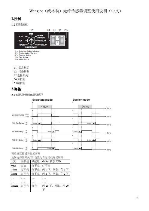
Wenglor(威格勒)光纤传感器调整使用说明(中文)1.控制1.1控制面板01.状态指示02.污染报警07.选择开关24.加按钮25.减按钮2.调整2.1延迟接通和延迟断开调整延迟接通和延迟断开延迟加按钮减按钮Gelbe 状态LED0ms 灯亮灯不亮灯不亮10ms 灯不亮灯不亮闪1下,间歇,闪1下20ms 灯不亮灯不亮闪2下,间歇,闪2下。
200ms 灯不亮灯亮闪20下,间歇,闪20下调整延迟接通调整延迟断开设置旋转选择器开关(07)在延迟接通设置旋转选择器开关(07)延迟断开激活加号按钮(24)。
延迟增加10 ms激活负按钮(25)。
延迟减少10 ms设置旋转选择器开关(07)来运行2.2选择常闭或常开功能设置旋转选择器开关(07)在常闭/常开(PNP / NPN型)激活加号按钮(24)NC是选定的(常闭/暗开关)---加号按钮(24)点亮---激活负按钮(24)NO是被选中(常开/光开关)---减去按钮(24)点亮设置旋转选择器开关(07)来运行2.3选择PNP / NPN 模式设置旋转选择器开关(07)NC/NO PNP / NPN模式激活加号按钮(24)为5秒---加号按钮(24)和负按钮(25)闪烁释放加号按钮(24)激活加号按钮(24)---加号按钮(24)点亮---PNP型设置激活负按钮(25)---减去按钮(25)点亮----NPN型设置同时激活加号按钮(24)和负按钮(25)加号按钮(24)和负按钮(25)点亮Push-pull setting 设置旋转选择器开关(07)来运行2.4设置开关距离与电位计设置旋转选择器开关(07)电位计激活加号按钮(24)---开关距离增加激活负按钮(25)---开关距离减少加减按钮上的LED的亮度指示加减的程度、相对应的的按钮越亮,感应距离越大,反之亦然。
如果最大值或最小值传感距离被选中相应的按钮会闪烁。
设置旋转选择器开关(07)来运行2.5用自学习功能设置开关距离用自学习功能设置理想的开关感应距离2.5.1标准模式设置旋转选择器开关(70)----红色LED(02)点亮适当放置目标对象激活加号按钮(24)---加号按钮(24)点亮激活加号按钮(24)再次*---加号按钮(24)不再是明亮的设置旋转选择器开关(07)来运行*如果在40秒内第二个按钮没有被操作,自学习过程被取消并不保存任何设置2.5.2Minimal Teach-In设置旋转选择器开关(07)适当放置目标对象激活减号按钮(25)---减号按钮(25)点亮激活减按钮(25)再次*---减号按钮(25)不再是明亮的设置旋转选择器开关(07)来运行The contamination warning is out of order during minimal Teach-In2.5.3Dynamic Teach-In (Teach-In with moving objects)设置旋转选择器开关(07)按下并保持住(约5秒)加号按钮(24)直到(24)闪烁---传感器是现在在记录模式,获得最小和最大入射光信号激活加号按钮(24)再次---记录模式是结束---加号按钮(24)不再是明亮的设置旋转选择器开关(07)来运行在自学习模式时传感器不会输出扫描和屏障模式在记录模式时,传感器根据入射光信号的最小和最大值之间自动确定理想的开关点。
在线组件.com E3F3光电传感器说明书

on e n t s .co mE3F3 Photoelectric Sensor1Threaded Cylindrical Photoelec-tric Sensor with Built-in Amplifi-er for Use as an Optical Proximity SensorHigh Noise-immunity with Photo-IC Technology•Up-to-date photo-IC to increase noise immunity.•M18 DIN-sized cylindrical housing, ABS resin case.•Long sensing distance (30 cm) with sensitivity adjus-tor for diffuse type.•Short-circuit and reverse connection protection.<READ AND UNDERSTAND THIS CATALOG>Please read and understand this catalog before purchasing the products. Please consult yourOMRON representative if you have any questions or comments.Ordering Informationo nl i ne c om p on e n t s .co m2E3F3 Photoelectric Sensor■Model Number Legend■Accessories (Order Separately)Note:E39-R1 is included in E3F3-R @@ and E3F3-R @@M.Specifications■Ratings/CharacteristicsNameModelReflectorE39-R1, E39-R3Reflector (tape type)E39-RS1, E39-RS2, E39-RS3Lens Cap E39-F31Mounting BracketY92E-B18ItemSensing method Through-beam RetroreflectiveDiffuse reflectiveNPN outputE3F3-T11E3F3-R11E3F3-R12E3F3-D11E3F3-D12E3F3-T16E3F3-R16E3F3-R17E3F3-D16E3F3-D17E3F3-T61E3F3-R61E3F3-R62E3F3-D61E3F3-D62E3F3-T66E3F3-R66E3F3-R67E3F3-D66E3F3-D66PNP outputE3F3-T31E3F3-R31E3F3-R32E3F3-D31E3F3-D32E3F3-T36E3F3-R36E3F3-R37E3F3-D36E3F3-D37E3F3-T81E3F3-R81E3F3-R82E3F3-D81E3F3-D82E3F3-T86E3F3-R86E3F3-R87E3F3-D86E3F3-D87Sensing distance 5 m3 m (Non-polarized when us-ing E39-R1) 2 m (Non-polarized when us-ing E39-R1)100 mm 300 mmStandard sensing object Opaque object: 11mm min.Opaque object: 56mm min.100 × 100 mm white mat paperHysteresis---20% max. of sensing distanceLight source (wavelength)Infrared LED (860 mm)Red LED (680 mm)Infrared LED (860 mm)Power supply voltage 12 to 24 VDC ±10%, ripple (p-p): 10% max.Current consumption 45 mA max. (light source and receiver)25 mA max.Control output Open collector transistor output, 100 mA max., residual voltage: 1 V max. at 100 mA Protective circuit Output short-circuit protection, DC power supply reverse polarity protection Response time 1.0 ms max.Sensitivity adjustment ---Single-turn adjusterAmbient illumination Incandescent lamp: 3,000 l x max., Sunlight: 10,000 l x max.Ambient temperature Operating: –25 to 55 °C (with no icing or condensation)Storage: –30 to 70 °C (with no icing or condensation)Ambient humidity Operating: 45% to 85% (with no condensation)Storage: 35% to 95% (with no condensation)Insulation resistance 20 M Ω min. (at 500 VDC) between current carry parts and case Dielectric strength 1,000 VAC at 50/60 Hz for 1 min between current carry parts and case Vibration resistance (destruction)10 to 55 Hz, 1.5-mm double amplitude for 1 hour each in X, Y , and Z directions Shock resistance (destruction)500 m/s 2 for 3 times each in X, Y , and Z directionsDegree of protection IEC 60529 IP66Connecting method Pre-wired (standard length: 2 m)/M12 connectorIndicatorsOperation indicator (orange) [Power indicator of emitter (orange)]Weight Pre-wiredMetal: 200 g max.Metal housing: 100 g max.Plastic: 170 g max.Plastic housing: 85 g max.M12 connectorMetal: 120 g max.Metal housing: 60 g max.Plastic: 40 g max.Plastic housing: 20 g max.Packing Nylon bag MaterialCase Plastic: ABS, Metal: Nickel-brass Lens PMMAAccessoriesScrew nuts: ABS or Nickel-brassAccessoriesScrew nuts (4),Instruction sheetScrew nuts (2),E39-R1 reflector,Instruction sheetScrew nuts (2),Instruction sheetScrew nuts (2),Instruction sheet,Adjusting driverE3F3 Photoelectric Sensor3Engineering Datai m4E3F3 Photoelectric SensorOperation■NPN Output■PNP Outputo e c .co E3F3 Photoelectric Sensor5DimensionsNote:All units are in millimeters unless otherwise indicated.■SensorsNote:Pre-wired Cord:Polyvinyl chloride-covered cord, 4-mm dia. (18/0.12), Standard length: 2 mEmitter: 2-conductor (brown and blue)Receiver and Reflective model: 3-conductor (brown, blue, and black)M12 connector: 1: +V, 2: NC, 3: 0 V, 4: Output2422E3F3-D @249.442.43724E3F3-D @2M422E3F3-D @724E3F3-D @7M2224E3F3-R @2E3F3-D @1247.7E3F3-R @1M E3F3-R @2M E3F3-D @1M2224E3F3-D @62427.7E3F3-D @6Mo nl i ne c om p on e n t s .co m6E3F3 Photoelectric Sensor■Accessories (Order Separately)E39-R3 RetroreflectorE39-RS1 RetroreflectorE39-RS2 Retroreflector1134.819.3T wo, M32.61.2343841.810.125.4+0.11.2T wo, M30.220381.210534R25.416T wo, 3.2 dia.11200.20.214513.7293.4R204.53.4718.4562822.93.4Adhesiveside 25.4Mounting Bracket for E39-K3(Sold Together)E39-RS3 RetroreflectorAdhesive tape sideAdhesive tape sideAdhesive tape sideMaterial: Acrylic resinMaterial: Acrylic resinMaterial: Acrylic resino nl i ne c om p on e n t s .co mE3F3 Photoelectric Sensor7PrecautionsIf the input/output lines of the photoelectric sensor are placed in the same conduit or duct as power lines or high-voltage lines, the photo-electric sensor could be induced to malfunction, or even be dam-aged, by electrical noise. Separate the wiring, or use shielded lines as input/output lines to the photoelectric sensor.Do not subject the photoelectric sensor to excessive shock when mounting, in keeping with IP66 standards.When you use the photoelectric sensor in the vicinity of an inverter motor, be sure to connect the protective ground wire of the motor to ground. Failure to ground the motor may result in malfunction of the sensor.MountingDo not exceed a torque of 20 kgf·cm (2.0 N·m) when tightening mounting nuts.!WARNINGThe E3F3 Photoelectric sensor is not a safety component for en-suring the safety of people as defined by EC Directives (91/386EEC) and covered by separate European standards or by any oth-er regulations or standards.E39-F31 Lens Cap32+0.217 max.718 dia.3047 max.4 max.o nl i ne c om p on e n t s .co mREAD AND UNDERSTAND THIS DOCUMENTPlease read and understand this document before using the products. Please consult your OMRON representative if you have any questions or comments.WARRANTYOMRON’s exclusive warranty is that the products are free from defects in materials and workmanship for a period of one year (or other period if specified) from date of sale by OMRON.OMRON MAKES NO WARRANTY OR REPRESENTATION, EXPRESS OR IMPLIED, REGARDING NON-INFRINGEMENT, MERCHANTABILITY, OR FITNESS FOR PARTICULAR PURPOSE OF THE PRODUCTS. ANY BUYER OR USER ACKNOWLEDGES THAT THE BUYER OR USER ALONE HAS DETERMINED THAT THE PRODUCTS WILL SUITABLY MEET THE REQUIREMENTS OF THEIR INTENDED USE. OMRON DISCLAIMS ALL OTHER WARRANTIES, EXPRESS OR IMPLIED.LIMITATIONS OF LIABILITYOMRON SHALL NOT BE RESPONSIBLE FOR SPECIAL, INDIRECT, OR CONSEQUENTIAL DAMAGES, LOSS OF PROFITS OR COMMERCIAL LOSS IN ANY WAY CONNECTED WITH THE PRODUCTS, WHETHER SUCH CLAIM IS BASED ON CONTRACT, WARRANTY , NEGLIGENCE, OR STRICT LIABILITY .In no event shall responsibility of OMRON for any act exceed the individual price of the product on which liability is asserted.IN NO EVENT SHALL OMRON BE RESPONSIBLE FOR WARRANTY , REPAIR, OR OTHER CLAIMS REGARDING THE PRODUCTS UNLESS OMRON’S ANALYSIS CONFIRMS THAT THE PRODUCTS WERE PROPERLY HANDLED, STORED, INSTALLED, AND MAINTAINED AND NOT SUBJECT TO CONTAMINATION, ABUSE, MISUSE, OR INAPPROPRIATE MODIFICATION OR REPAIR.SUITABILITY FOR USETHE PRODUCTS CONTAINED IN THIS DOCUMENT ARE NOT SAFETY RATED. THEY ARE NOT DESIGNED OR RATED FOR ENSURING SAFETY OF PERSONS, AND SHOULD NOT BE RELIED UPON AS A SAFETY COMPONENT OR PROTECTIVE DEVICE FOR SUCH PURPOSES. Please refer to separate catalogs for OMRON's safety rated products.OMRON shall not be responsible for conformity with any standards, codes, or regulations that apply to the combination of products in the customer’s application or use of the product.At the customer’s request, OMRON will provide applicable third party certification documents identifying ratings and limitations of use that apply to the products. This information by itself is not sufficient for a complete determination of the suitability of the products in combination with the end product, machine, system, or other application or use.The following are some examples of applications for which particular attention must be given. This is not intended to be an exhaustive list of all possible uses of the products, nor is it intended to imply that the uses listed may be suitable for the products:•Outdoor use, uses involving potential chemical contamination or electrical interference, or conditions or uses not described in this document.•Nuclear energy control systems, combustion systems, railroad systems, aviation systems, medical equipment, amusement machines, vehicles, safety equipment,and installations subject to separate industry or government regulations.•Systems, machines, and equipment that could present a risk to life or property.Please know and observe all prohibitions of use applicable to the products.NEVER USE THE PRODUCTS FOR AN APPLICATION INVOLVING SERIOUS RISK TO LIFE OR PROPERTY WITHOUT ENSURING THAT THE SYSTEM AS A WHOLE HAS BEEN DESIGNED TO ADDRESS THE RISKS, AND THAT THE OMRON PRODUCT IS PROPERLY RATED AND INSTALLED FOR THE INTENDED USE WITHIN THE OVERALL EQUIPMENT OR SYSTEM.PERFORMANCE DATAPerformance data given in this document is provided as a guide for the user in determining suitability and does not constitute a warranty. It may represent the result of OMRON’s test conditions, and the users must correlate it to actual application requirements. Actual performance is subject to the OMRON Warranty and Limitations of Liability.CHANGE IN SPECIFICATIONSProduct specifications and accessories may be changed at any time based on improvements and other reasons.It is our practice to change model numbers when published ratings or features are changed, or when significant construction changes are made. However, some specifications of the product may be changed without any notice. When in doubt, special model numbers may be assigned to fix or establish key specifications for your application on your request. Please consult with your OMRON representative at any time to confirm actual specifications of purchased products.DIMENSIONS AND WEIGHTSDimensions and weights are nominal and are not to be used for manufacturing purposes, even when tolerances are shown.ERRORS AND OMISSIONSThe information in this document has been carefully checked and is believed to be accurate; however, no responsibility is assumed for clerical, typographical, or proofreading errors, or omissions.PROGRAMMABLE PRODUCTSOMRON shall not be responsible for the user’s programming of a programmable product, or any consequence thereof.COPYRIGHT AND COPY PERMISSIONThis document shall not be copied for sales or promotions without permission.This document is protected by copyright and is intended solely for use in conjunction with the product. Please notify us before copying or reproducing this document in any manner, for any other purpose. If copying or transmitting this document to another, please copy or transmit it in its entirety.In the interest of product improvement, specifications are subject to change without notice.ALL DIMENSIONS SHOWN ARE IN MILLIMETERS.To convert millimeters into inches, multiply by 0.03937. T o convert grams into ounces, multiply by 0.03527.Cat. No. E365-E1-01OMRON CorporationIndustrial Automation CompanySensing Devices Division H.Q.Industrial Sensors Division Shiokoji Horikawa, Shimogyo-ku,Kyoto, 600-8530 JapanT el: (81)75-344-7022/Fax: (81)75-344-7107Printed in Japan 0605-?M (0605) (?)。
安装指南- extron fox3 sr 201 光纤缩放接收器说明书

1I M P O .e x t r o n .c o m f o r t i o ni n s t r u c ti on s ,e c t i n g t h eFOX3 SR 201 • Setup GuideThis guide provides quick start instructions for an experienced installer to set up and operate the Extron FOX3 SR 201 Fiber Opticscaling receivers. This scaling receiver scales resolutions up to 4K @ 60 Hz, 4:4:4 video, and extends with 2-CH audio, RS-232, and IR over fiber. The FOX3 SR 201 is available in either singlemode (SM) or multimode (MM) transmission mode.InstallationREMOTEPOWER 12V2.0A MAXA OUT IN BOUT INLANHDMIFOX3 SR 201RAUDIOCONTROLOUTPUTSIG F C A D H E BFigure 1.FOX3 SR 201 Rear PanelA Power Inlet F Remote RS-232B Power LED G LAN Ethernet portC Audio output H SFP module and LEDsD HDMI output I Reset buttonE Control RS-232/IR portStep 1 — MountingTurn off or disconnect all equipment power sources and mount the scaling receiver as required. For mounting details and considerations, see the FOX3 SR 201 User Guide at .Step 2 — Output Connectionsa. D ).b. C ) (see figure 2 to wire the captive screwUnbalanced Stereo OutputBalanced Stereo Output LRLRa. To pass serial, IR data, or control signals, such as for serial control of a projector,connect the master device to the transmitter and the controlled device to thereceiver via the CONTROL 5-pole captive screw connector (see E and figure 3 for wiring).Figure 3. RS-232 and IR Wiring2FOX3 SR 201 • Setup Guide (Continued)b. For remote control of a unit and loading firmware (LAN or USB only), connect a host device, such as a computer or controlsystem, to one of the following ports (see the FOX3 SR 201 User Guide , available at , for details):•Remote RS-232 port — Connect the 3-pole captive screw connector to this port (F ). The protocol for the Remote port is as follows:• 9600 baud • no parity • 8 data bits • 1 stop bit • no flow control• LAN Ethernet port — Connect an RJ-45 connector to this port (G ).•USB Configuration port — Connect a USB mini-B connector to this port (see figure 5, B on page 2).Step 4 — Throughput Connections).b. to the transmitter, connect a cable between the A Out port on the receiver and A In port on the transmitter (2).c. To transmit an uncompressed 4K @ 60 Hz signal, using the Uncompressed Video LinkLicense,repeat step 4a on the SFP B port on the scaling receiver SFP Link LEDs — ReceiverFigure 4.Fiber Cable Connection• Transmit Optical OUT LED — Lights solid green when powered and lights off when there is no power on the endpoint.•Receive Optical IN LED — Lights solid green when light is present and lights off when there is no power or light present.Step 5 — Power ConnectionConnect the included external 12 VDC power supply into the 2-pole connector (see figure 1, A on page 1). The power LED lights (B ) when the unit is receiving power.OperationAfter the receiver, transmitter, and their connected devices are powered up, the system is fully operational. If any problems are encountered, verify that the cables are routed and connected properly and the display device has a compatible resolution and refresh rate. If problems persist, call the Extron S3 Sales & Technical Support Hotline (see the contact number on page 6).FOX3 SR 201MENUINPUTSIGNAL HDCPENTER C AD EB Figure 5.FOX3 SR 201 Front PanelA Power LED — Indicates power is applied to the unit.B USB Config port — Connect a USB Mini-B cable to a computer to configure the device and update the firmware via ProductConfiguration Software (PCS), Simple Instruction Set (SIS) commands, or internal web pages.C Input LEDs —• Signal LED — Lights when the unit detects an input video signal.•HDCP LED — Lights when the input signal is HDCP encrypted.D Menu and Enter buttons — Press these buttons to access and navigate the on-screen display menu system.E Navigation buttons — Press these buttons to navigate through the on-screen display menu system or change settings. ResetPress the rear panel recessed reset button (see figure 1, I on page 1) if the FOX3 scaling receiver firmware is corruptedor the unit gets disconnected during the update process. The different resets allow the device to revert to the factory loaded firmware, reset IP seetings, or reset configuration to default (see the Reset Modes table, for details on the reset modes).Front Panel Lockout Mode (Executive Mode)The front panel lockout mode limits operation of the device from the front panel. When enabled, use SIS commands or the Product Configuration Software (PCS) to configure the device. To enable or disable the front panel lockout mode through the front panel, press and hold the Menu (see figure 5, D on page 2) and down arrow (E) buttons simultaneously for 5 seconds oruntil the power LED blinks.34FOX3 SR 201 • Setup Guide (Continued)Configuration and ControlTo configure the FOX3 SR, use the front panel controls and the on-screen display (OSD) menu, Simple instruction Set (SIS) commands, or PCS.On-screen display menu systemThe OSD menu consists of two submenus, Device Info and Setup , that can be accessed using the front panel Menu button. View the menu on a display connected to the HDMI output connector (see figure 1, D on page 2). The Device Info submenu is view only. The following fields can be configured from the Setup submenu:•Output Rate — Select from a list of refresh rates (see Output Resolution table on page 5). The default setting is 1080p @ 60 Hz.•HDMI Format — Select the output format:• Auto (default)• DVI RGB 444• HDMI RGB 444 Full • HDMI RGB 444 Limited • HDMI YUV 444 Full • HDMI YUV 444 Limited • HDMI YUV 422 Full •HDMI YUV 422 Limited• Test Pattern — Select an available test pattern to display or turn a test pattern off. The available test pattern selections are Crop, Alternating Pixels, Crosshatch, and Color Bars. The default setting is Off.•Factory Reset — Reset the unit to its factory default values (removing any user-specified values) while retaining all TCP/IP settings.To adjust settings:1. Press the Menu button to access the main menu.2. Press the directional arrows to navigate to a desired submenu.3. Press the Enter button to access submenu items of a selected submenu.4. Press the directional arrows to navigate a desired submenu item.5. Press the Enter button to select a submenu item for adjustment.6. As required, press the directional arrows or press the Enter button to adjust submenu items.7. Press the Menu button to return to the list of submenus or exit the OSD menu.Product Configuration SoftwareThe FOX3 scaling receiver can be configured via the Product Configuration Software when it is installed on a connected host device, such as a PC, through the front panel USB port or LAN port (see the FOX3 SR 201 User Guidefor more details).Internal Web PagesTo configure the FOX3 SR 201 using the factory-installed internal web pages in a web browser, connect the LAN port on the receiver to a LAN or WAN. The default IP address is 192.168.254.254. Basic Scaler SIS CommandsUse Simple Instruction Set (SIS) commands for operation and configuration of the scaling receiver using a PC connected to:• A LAN or WAN using the rear panel RJ-45 LAN port (see figure 1, G on page 1) via an SSH client and port 22023.• The Remote RS-232 port (see figure 1, F ) via DataViewer.• The front panel USB config port (see figure 5, B on page 2) via an SSH client using IP address 203.0.113.22 and port 22023.Command and Response Table for SIS Commands*Default output resolution5668-2888-50 Rev. A04 21For information on safety guidelines, regulatory compliances, EMI/EMF compatibility, accessibility, and related topics, see the Extron Safety and Regulatory Compliance Guide on the Extron website.© 2021 Extron — All rights reserved. All trademarks mentioned are the property of their respective owners.Worldwide Headquarters: Extron USA West, 1025 E. Ball Road, Anaheim, CA 92805, 800.633.9876。
3M光缆探测仪使用说明

3M Dynatel TM 2273E光缆/电缆外皮故障及路由探测仪Dynatel TM 2273E是一种具有微型处理器的电缆(光缆)外皮故障及路由探测仪,能快速有效地确定地下的电缆走向和深度,及确定外皮故障。
轻巧、结实的2273E能准确地:* 确定电缆(光缆)的走向* 探测电缆(光缆)的深度* 探测电缆的信号电流* 探测外皮故障及电缆的破坏处* 识别电缆外皮故障的轻重程度* 探测架空电缆的短路或碰地故障* 确定受潮部分的电缆线对* 探测电力电缆2273E能准确确定电缆深度,用厘米、英尺、英寸来显示。
另外,当与3M EMS2205及2206电子标志器定位仪相配使用时,其系统具有:* 能准确探测出所埋的电子标志器的位置* 同步进行寻找电子标志器及跟踪电缆走向四种工作方式即使在复杂的地段也能精确定位确定电缆或光缆的走向,接收器有四种工作方式:峰值,反峰值,差分值或特殊峰值(用来加强追踪长距离的灵敏度),用户可以根据实际情况选择有效的工作方式。
接收器有四种容量,此外还有一个“扩展器”功能,使得峰值与反峰值测量更为明确。
如果两导体带相同频率的信号,该扩展器依据不同的振幅将它们区分开来,从而使结果更为准确,该信号含有耳机插座。
准确确定故障2273E能确定各种长度的电缆故障,2273E可同时发出一个路由跟踪音信号和一个故障定位音信号。
操作者可在探测路由的同时使用外皮故障定位功能,并由2273E区别故障程度。
简易操作系统使用2273E探测仪,不需要特别培训,液晶显示屏幕及触摸式的按钮使使用更为简便。
“记忆储存功能” 能记录有关探测情况。
此系统有三部分组成:* 具有欧姆表的发射器,能探测外部电压及测试持续的环路电阻* 带有图形的接收器用于指示信号的强弱以及电缆定位* 触地支架…… 配有色标,用于确定故障方位2273E 探测仪具有四种有源跟踪频率:577Hz,8KHz ,33KHz和133KHz,依据具体实际情况,可以单独或同时使用来补偿现场条件的变化,同时有两种无源跟踪频率50、60Hz和低频信号(LF)(无需使用发射器)。
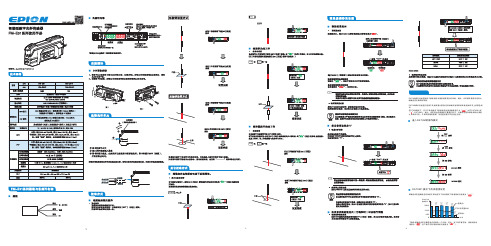
智能型数字光纤传感器FM-E31使用说明书
时间
DATUM指 打开 示灯闪烁 关闭
4
5
6
进入DATUM的操作模式
DATUM1 模式下的灵敏度设定
灵敏度设定值始终会自动校正,因此在无工件的情况下接收到的光强度为“ ”。
无DATUM
检测显示 2000
DTM1 显示 1000
DTM1 显示 1000
DTM 显示 1000
DTM1 显示 1000
DTM1 显示 1000
校准点1
1200
400 0
无DATUM 检测显示
DTM2 显示0
2000
DTM2 显示0
DTM2 显示0
DTM2 显示0
DTM2 显示0
校准点1
1200
400 0
DTM2 显示 800
DTM2 显示 800
DTM2 显示 800
DTM2 显示 800
DTM2设定值400
DTM2
显示 800
校准点2
时间
下面的灵敏度设定步骤是两点校准的一个示例(其中,当工件不存在时,接收到的光 强度为“ ”;当工件存在时,接收到的光强度为“ ”)。
更改警告输出电平
DATUM警告值为无工件接受到的光强度和设定值的中间值,如果接收到的光强度介于警告 值和设定值之间时,接收到的光强度会停止校正,并且DTM指示灯闪烁警告。
1000 800 400
200 0
如果在无工件情况下接收到的光强度没有 上升到警告值(例如,由于光轴未对齐),则 DTM指示灯闪烁警告
校准点1
反光较 强的背景
DTM指示灯亮起
在工件存在的情况下,按[SET](设定)按钮 校准点2
反光较 弱的工件
光纤光栅感温火灾探测系统使用说明书

光纤光栅感温火灾探测系统使用说明书北京奥普智信光科技术有限公司目录1概述 02光纤光栅感温火灾探测系统主要技术指标 02.1光纤光栅感温火灾探测器 02.2光纤光栅感温火灾信号处理器 03光纤光栅感温火灾探测系统主要功能 (1)4光纤光栅感温火灾探测系统基本组成 (1)4.1光纤光栅感温火灾探测器 (2)4.2光缆 (2)4.3光纤接续盒 (2)4.4AP658-02B-40-4815II型光纤光栅感温火灾信号处理器 (2)1)光纤光栅解调器前面板 (3)2)光纤光栅解调器后面板 (5)5可视化监控软件 (7)6 系统安装 (8)6.1连接关系 (8)6.2系统安装 (8)6.3系统参数设置 (10)7操作使用 (10)7.1启动运行 (10)7.2系统故障状态 (10)7.3系统预警状态 (10)7.4系统火灾状态 (10)7.5系统正常状态 (11)7.6消除报警声音 (11)8 维护与保养 (11)8.1操作注意事项 (11)8.2日常维护与保养 (11)9 常见故障及排除方法 (11)1概述光纤光栅感温火灾报警探测系统是一种新型的温度探测报警系统。
系统采用最新生产工艺,长期稳定性好,使用寿命长;光纤光栅感温火灾探测信号处理器采用国际最先进地数字化解调技术,具有大容量实时在线信号采集处理和自检功能;系统可以综合各种安全监控参数,进行分析,有利于及时发现事故苗头,及时安全控制,实现油库的生产和安全的双重监控功能。
从光纤光栅感温探测器到监控中心光纤光栅感温火灾信号处理器传输全部采用光信号,实现无电检测,本质安全防爆,适合于石油、化工、电力等场所使用2光纤光栅感温火灾探测系统主要技术指标2.1 光纤光栅感温火灾探测器1)测温范围:-30℃~120℃2)测量精度:±2℃3)温度分辨率:0.1℃4)响应时间: < 2S5)光信号最大传输距离:≤10km6)相对湿度:≤90%2.2 光纤光栅感温火灾信号处理器1)电源供电方式: 220V AC 50Hz2)报警温度设定范围:65℃~105℃3)每通道最大传感器点数:20个/通道4)信号处理器每一通道响应时间:<0.38s5)测量光缆通道数:1~64通道6)环境温度:-5~50℃7)相对湿度:≤90%3光纤光栅感温火灾探测系统主要功能1)具有自检功能,可实时监测运行状况,并对故障点进行报警2)定温报警温度设置:65℃~105℃,参数可现场设置3)报警级别设定:预警、火警2级报警4)报警设备上具有人工复位按钮,出现报警后必须人工复位后才能取消报警信号。
D-21FMA3100系列气体流量传感器说明书

D-21FMA3100 SeriesU F or Flow Rates Up to 10 SLM U 0 to 5 Vdc Linear Output U Cost EffectiveFMA3100 Series mass flow sensors represent a breakthrough in mass flow sensor technology. State-of-the-art electronics, a compact mechanical design, and mass production tooling concepts arecombined into one high-performance, cost effective product. The gas flow sensor is suitable for many OEM applications. A 0 to 5 Vdc linear output is standard.Using the basic FMA3100 thermal mass flow sensor, the FMA3200 mass flow controllers offeraccurate, stable control of gas flows in a compact package. In power-off mode, the flow control valve is closed with a minimal leak rate. This cost-effective controller is ideal for many OEM applications, with a 0 to 5 Vdc linear output and a 0 to 5 Vdc control input.The FMA3300s combine the features of the FMA3100 with an adjustable 31⁄2 digit LCD digitaldisplay meter for viewing flow rate in engineering units (i.e., mL/min or L/min). These compact flowmeters have proved effective in many laboratory applications.Economical GaS maSS Flow controllErS and mEtErSFor clean Gases GENERAL SpECiFiCAtiONSOutput: 0 to 5 Vdc (2500 Ω minimum)input Setpoint Voltage (FMA3200 Only): 0 to 5 Vdc Accuracy: ±1.5% FS*Repeatability: ±0.5% FSResponse time: 2 seconds (typical) to within ±2% of actual flow rate from 25 to 100% of full scaleOperating Ambient: 10 to 50°C (50 to 122°F), non-condensing atmosphere Operating pressure Range:To 150 psi maximum at 25°C (77°F)temperature Coefficient: ±0.2% per °Cpressure Coefficient: ±0.02% per psi Leak integrity: 1x10⁻⁴ SCCSHe maximum to outside environments input power:FMA3100 and FMA3300: 12 to 15 Vdc, 100 mA (1.5 W) FMA3200: 12 to 15 Vdc, 250 mA (3.75 W)Connections: 1⁄8" compression fittings, flow ranges up to 1 L/min; 1⁄4" compression fitting for up to 5 L/min; 3⁄8" compression fitting for 10 L/min Wetted Materials:Anodized aluminum, FKM O-rings, 304 and 316 SS, epoxy, acetal compression tube fittings standard turndown Ratio: 10:1Gases: Most clean, dry gases (e.g., air, nitrogen, carbon dioxide, argon, hydrogen, helium, methane, oxygen)Filtration: Requires 20-micron filter if gas contains any particulate matterSpECiFiCAtiONS(FMA3200 Flow Controllers)Differential pressure: 15 to 40 psiFMA3206 mass flowcontroller, shown actual size.* Stated accuracy under general specifications valid for the following conditions:1. T emperature between 18 and 25°C (64 and 77°F)2. Warm-up time: at least 10 min 3. Power input voltage stable (12V ±0.1V) typical4. Linearity: Add ±0.5% for ranges up to 500 SCCM, ±1.0% over 500 SCCM5. Accuracy range: 10 to 100%6. Line pressure of 1 to 30 psi for FMA3100 and FMA3300, and at factory-specified settings for FMA32007. Factory gas (specified) is usedValve Cycle Life: >1 million cycles; valve is normally closed Control Range: 50:1Remote Setpoint Voltage: 0 to 5 Vdc Weight:FMA3100: 199 g (0.44 lb) FMA3300: 249 g (0.55 lb) FMA3200: 386 g (0.85 lb)Size Without Fittings (Approx.): FMA3100: 47 L x 26 W x 90 mm H (1.87 x 1.03 x 3.55")FMA3300: 47 L x 26 W x 127 mm H (1.87 x 1.03 x 5.0")FMA3200: 81 L x 26 W x 97 mm H(3.17 x 1.03 x 3.80")OptionalD-22DModels shown smaller than actual size.FMA3303 flow sensorFMA3101 flow sensorFor optional 4-point NIST calibration certificate add suffix “-NISTAIR” to model number for additional cost.Ordering Example: FMA3307, 0 to 2000 SCCM flow meter with display, and FMA3115PW , power supply/output cable.* Specify gas, inlet/outlet pressure and temperature.** Flow ranges are based on dry air ornitrogen as a standard; other gases available (carbon dioxide, helium, argon, hydrogen, methane, oxygen) for an additional cost.For optional 4-point NIST calibrationcertificate add suffix “-NISTAIR” to model number, for additional cost.Ordering Example: FMA3203-(Helium, 20/0 psig, 70°F), 0 to 100 SCCM flowcontroller, and FMA3215PW , power supply/output cable.。
E+H电容物位计FMI21操作说明

20 mA 100 %
FEI20
– 4...20 mA
+
–+
12
+–
2.
z 0.0
z
0…100 %
ᡆ
㔯(gn) 0.5 s
4.0 mA
V=
V~
A
10 s ؍ᆈ
0. 0
0…100 %
ᡆ
㔯(gn) 4s
4.0 mA
V=
V~
A
Endress + Hauser
A
B
1.
2s
–
+
FEI20
– 4...20 mA
W
A661 电子插件温度过高
W
电流输出的影响 优先级
22 mA
1
–
5
22 mA
2
22 mA
3
22 mA
4
6
3.8 mA 20.5 mA
7
8
错误代号
故障 无测量值
测量值错误
红色 LED 指示灯闪烁
原因 无供电电压 信号线故障
电子插件故障 - FEI20 直接连接至 L1 和 N 标定错误 安装的杆式传感器损坏 液体电导率过低 报警 (A) / 警告 (W)
63 % 0.15 s
输出阻尼时间 延迟输出信号时间
t
t 25
技术参数 环境温度 Ta 过程温度 Tp
26
Ta Tp
⍻䟿㋮ᓖ䱽վʽ
Ta
80 70 60 50 40 30 20 10
0
–40 –30 –20 –10 0 10 20 30 40 50 60 70 80 90 100 Tp
–10 –20 –30 –40