电子元器件应用-Agilent T150 UTM Data Sheet
Agilent Technologies 8110A 150 MHz Pulse Generator
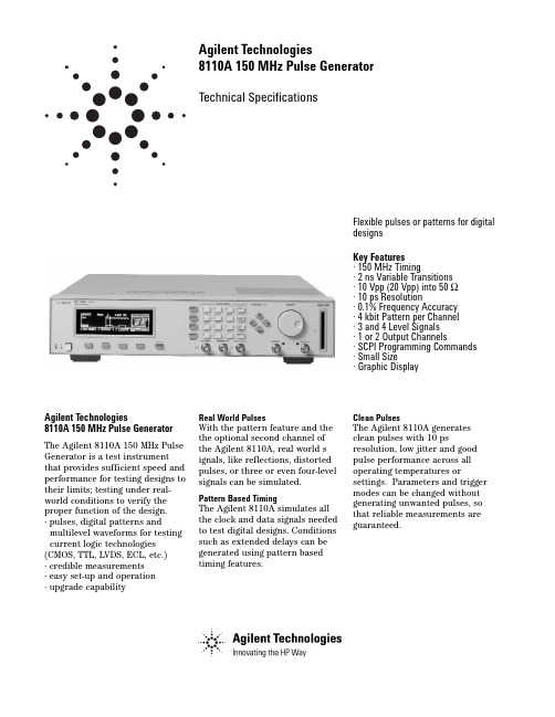
Agilent Technologies8110A 150 MHz Pulse GeneratorTechnical SpecificationsFlexible pulses or patterns for digital designsKey Features · 150 MHz Timing· 2 ns Variable Transitions · 10 Vpp (20 Vpp) into 50 Ω · 10 ps Resolution· 0.1% Frequency Accuracy · 4 kbit Pattern per Channel · 3 and 4 Level Signals · 1 or 2 Output Channels· SCPI Programming Commands · Small Size· Graphic DisplayAgilent Technologies8110A 150 MHz Pulse GeneratorThe Agilent 8110A 150 MHz Pulse Generator is a test instrumentthat provides sufficient speed and performance for testing designs to their limits; testing under real-world conditions to verify the proper function of the design.· pulses, digital patterns andmultilevel waveforms for testing current logic technologies (CMOS, TTL, LVDS, ECL, etc.)· credible measurements · easy set-up and operation · upgrade capabilityReal World PulsesWith the pattern feature and the the optional second channel of the Agilent 8110A, real world s ignals, like reflections, distorted pulses, or three or even four-level signals can be simulated.Pattern Based TimingThe Agilent 8110A simulates all the clock and data signals needed to test digital designs. Conditions such as extended delays can be generated using pattern based timing features.Clean PulsesThe Agilent 8110A generates clean pulses with 10 psresolution, low jitter and good pulse performance across all operating temperatures orsettings. Parameters and trigger modes can be changed without generating unwanted pulses, so that reliable measurements are guaranteed.2High AccuracyExcellent accuracy over a wide temperature range guarantees repeatable measurement results.Frequency accuracy, jitter,resolution and range can be enhanced further when the Agilent 8110A is used with the internal phase locked loop (PLL) of the Agilent 81106A as pulse period source.Delay CalibrationSystematic delays caused by cables,connections and adapters can be compensated when the Agilent81107A is installed. It offers enough additional delay range to compensate for 5 m of BNC cable.External Clock or Reference Frequency 1An external synthesizer or system clock can be used as clock source at the clock input of the Agilent 8110A to achieve the frequency accuracy and required. Thisfeature is ideal for simulating digital control signalssynchronously to the clock of the microprocessor.Up to 10 channels in parallel 2Up to 4 Agilent 8110As can be slaved to a master, so that 10synchronous channels can beprogrammed independently. With the Agilent 81107A multichannel deskew installed, the propagation delay of the set-up can becompensated, and all other output channels zeroed to the reference channel.Smooth Integration into Automated Test SystemsThe Agilent 8110A can be smoothly integrated into automated test systems, ensuring:·low integration costs ·low costs of ownershipAll Digital WaveformsThe waveform and triggerflexibility of the Agilent 8110A make it a universal digitalstimulus for any automated test sys-tem.Reliable MeasurementsAccuracy is specified over the whole temperature range that exists in a test rack. Setting check and built-in diagnostics allow you to monitor the correct operation of the Agilent8110A in an automated test system.Easy Rack IntegrationThe small size of the Agilent 8110A saves valuable rack space. Rear panel connectors and rack mount kits are optional.Reduced Programming InvestmentThe local user interface eases the transition from manual toautomated measurements and from the R&D bench toautomated manufacturing test. All parameters of the Agilent 8110A are programmable via GPIB. SCPI (Standard Commands for Programmable Instruments)facilitates the standardization of test programs.Low Cost of OwnershipThe proven hardware reliability of Agilent test and measurement prod-ucts results in high uptime of test systems and low maintenance costs.The Agilent 8110A offers a 3 year standard warranty.Easy Set-up and OperationView all timing parameters for both channels at a glance. Timing and level parameters can be entered in any format, e.g. period as frequency.The alternative graphic display shows the timing relationship of all pulse parameters on both channels graphically, making setting up the pulse generator easy - no extra oscilloscope is required.Pulses and patterns can be set up quickly using the convenient cursor keys, knob and data entry keys. You can even use the Autoset Key to resolve all timing conflicts.Memory CardSettings can be storedpermanently either internally or on the memory card for duplication in another test set-up.4Pattern ModePattern length:4 kbit/channel and strobe output.Output format:RZ (return to zero), NRZ (non-return to zero), DNRZ (delayed non-return to zero). Random pattern:PRBS 2^(n-1) n = 7,8,...,12Trigger ModesContinuous:continuous pulses, double pulses, bursts (single or double pulses) or patterns. External triggered:each active input transition (rising, falling or both) generates a single or double pulse, burst or pattern.External gated:the active input level (high or low) enables pulses, double pulses, bursts or patterns. The last single/double pulse, burst or pattern is alwayscompleted.External width:the pulse shapecan be recovered. Period and width ofan external input signal is main-tained. Delay, levels and transitionscan be set.Manual:simulates an external inputsignal.Internal triggered (only with Agilent81106A):internal PLL replaces anexternal trigger source. Pulses, doublepulses, bursts or patterns can be set.Inputs and OutputsExternal inputused for trigger, gate or externalwidth.Input impedance:50 Ω /10 kΩ selec-table.Threshold:- 10 V to + 10 V.Max. input voltage:± 15 Vpp.Sensitivity:≤300 mVpp typical.Transitions:< 100 ns.Frequency:dc to 150 MHzMin. pulsewidth:3.3 ns.Strobe output and trigger outputLevel:TTL or ECL selectable.Output impedance:50 Ω typical.Strobe output: user-defined, 16 kbit pat-tern (NRZ) when in pattern mode.Max. external voltage:- 2 V/+7 V.Transition times:2 ns typical.Pattern:4096 bits NRZ in patternmode.Delay from external input to strobeoutput:in pattern mode same as fortrigger output.Trigger OutputLevel:TTL or ECL selectableOutput impedance:50 ΩtypicalTrigger pulse width:typically 50% ofperiodMaximum external voltage:-2 V/+7 VTransition times:2 ns typicalDelay from external input to triggeroutput:l8.5 ns typicalAgilent 81107A Multichannel Deskew for the Agilent 8110ACan be retrofitted without recalibration. Supports twooutput channels. Themultichannel deskew can be used for two applications:Up to 10 channels:compensates delay between external input and trigger outputs when using up to five8110As synchronously.Delay calibration:compensates for measurement system delays or pre-trigger delays of oscilloscopes. Variable range:0 ns to 28 ns Additional fixed delay:6.5 ns typical Resolution:10 ps User InterfaceOverprogramming:all parameters canbe overprogrammed(exceeding specifications) to fullyexploit the hardware limits.Setting check:warning messages indi-cate potentially conflicting parame-ters due to inaccuracy.Error messages indicateconflicting parameters.Help key:displays a context-sensitive message.Autoset key:resolves all timing con-flicts.Non-volatile memory:currentsetting is saved on power-down.Up to nine user settings and one fixeddefault setting can be stored in theinstrument.Clear memory:clears all nine user set-tings.Memory card:320 settings can bestored on a 1 MB PCMCIA card(MS-DOS ).Remote ControlOperates according to IEEEstandard 488.2, 1987 and SCPI1992.0.Function Code:SH1, AH1, T6, L4, SR1,RL1, PP0, DC1, DT1, C0.Programming times:all checks anddisplay off.GeneralOperating temperature:0°C to +55°C.Storage temperature:-40°C to +70°C.Humidity:95% r.h. up to 40°C ambi-ent temperature.EMC:conforms to EN50082-1,EN 55011, Class A.Noise emission:5.7 bel typical.Battery:Lithium CR2477-N.Safety:IEC1010, CSA1010.Power requirements:100-240 Vac, ± 10%, 50-60 Hz;100-120 Vac, ± 10%, 400 Hz.Power consumption:300 VA max.Max. dimensions (H * W * D):89 mm * 426 mm * 521 mm.Weight: 9.2 kg net, 13.8 kgshipping.Recalibration period:one year recommended.Warranty:three years standard.6Ordering Information - 8110AT he minimum order must include the 8110A mainframe and one 81103A output channel. A second output channel, the 81106A PLL/external clock or the 81107A multichannel deskew are optional. All configurations are available from the factory. Alternatively, additional modules can be ordered later and fitted by the user or an Agilent service facility.Qty per Mainframe Categorymin max Description NumberMainframe[1]1150 MHz Pulse Generator Mainframe Agilent 8110AModules1210 V/2 ns Output Channel Agilent 81103A01PLL/External Clock Agilent 81106A01Multichannel Deskew Agilent 81107AAll options are orderable with the mainframes.AccessoriesOpt UN2Rear Panel ConnectorsOpt 1CP Rack Mount and Handle Kit (5062-3975)Opt 1CN Handle Kit (5062-3988)Opt 1CM Rack Mount Kit (5062-3974)Opt 1CR Rack Slide Kit (1494-0060)Opt UFJ 1 MB SRAM Memory CardAgilent 15104A Pulse Adder/SplitterLanguage optionsOpt ABD German Localization (08110-91112)Opt ABF French Localization (08110-91212)Opt ABZ Italian Localization (08110-91312)Opt ABE Spanish Localization (08110-91412)Opt ABJ Japanese Localization (08110-91512)Opt AB0Chinese Localization (08110-91612)Additional documentation optionsOpt 0B2 Additional English Operating Manual(08110-91012)Opt 0BW Service Manual (08110-91021)08110-91031Service Documentation (Component Level)Support OptionsOpt 1BP MIL Std. 45662A Calibration with Test DataOpt W32 3 Year Customer Return Calibration CoverageOpt W34 3 Year MIL Calibration ServiceOpt W50 5 Year Customer Return Repair CoverageOpt W52 5 Year Customer Return Calibration CoverageOpt W54 5 Year MIL Calibration Service7Related Agilent Literature·Agilent Family of Pulse/PatternGenerators, brochure, p/n 5980-0489EAgilent Technologies'Test and Measurement Support, Services, and AssistanceAgilent Technologies aims to maximize the value you receive, while minimizing your risk and problems. We strive to ensure that you get the test and measurement capabilities you paid for and obtain the support you need. Our extensive support resources and services can help you choose the right Agilent products for your applications and apply them successfully. Every instrument and system we sell has a global warranty. Support is available for at least five years beyond the production life of the product.Two concepts underlay Agilent's overall support policy: "Our Promise" and "Your Advantage."Our PromiseOur Promise means your Agilent test andmeasurement equipment will meet its advertised performance and functionality. When you are choosing new equipment, we will help you with product information, including realistic performance specifications and practical recommendations from experienced testengineers. When you use Agilent equipment, we can verify that it works properly, help with product operation, and provide basic measure-ment assistance for the use of specifiedcapabilities, at no extra cost upon request. Many self-help tools are available.Your AdvantageYour Advantage means that Agilent offers a wide range of additional expert test and measurement services, which you can purchase according to your unique technical and business needs. Solve problems efficiently and gain a competitive edge by contracting with us for calibration, extra-cost upgrades, out-of-warranty repairs, and on-site education and training, as well as design, system integration, project management, and other professional services. Experienced Agilent engineers and technicians worldwide can help you maximize your productivity, optimize the return on investment of your Agilent instruments and systems, and obtain dependablemeasurement accuracy for the life of those products.By internet, phone, or fax, get assistance with all your test & measurement needs Online assistance:/find/assist Phone or Fax United States:(tel)180****4844Canada:(tel)187****4414(fax) (905) 206 4120Europe:(tel) (31 20) 547 2000Japan:(tel) (81) 426 56 7832(fax) (81) 426 56 7840Latin America:(tel) (305) 267 4245(fax) (305) 267 4286Australia:(tel) 1 800 629 485 (fax) (61 3) 9272 0749New Zealand:(tel) 0 800 738 378 (fax) 64 4 495 8950Asia Pacific:(tel) (852) 3197 7777(fax) (852) 2506 9284Product specifications and descriptions in this document subject to change without notice.Copyright © 2000 Agilent Technologies Printed in Germany 10/20005980-1212EFor more information, please visit us :/find/pulse_generator。
Amprobe AM-150 TRMS数字多功能电 charts测试仪说明书
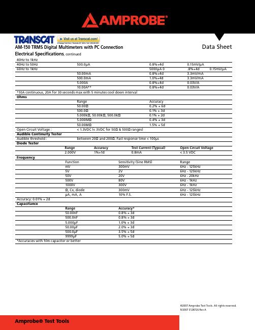
Data Sheet©2007 Amprobe Test Tools. All rights reserved.9/2007 3128726 Rev AAM-150 TRMS Digital Multimeters with PC Connection40Hz to 1kHz40Hz to 50Hz500.0μA 0.8%+4d 0.15mV/μA60Hz to 1kHz 5000μA 0 .8%+4d 0.15mV/μA50.00mA 0.8%+4d 3.3mV/mA500.0mA 1.0%+4d 3.3mV/mA5.000A 0.8%+4d 0.03V/A10.00A** 0.8%+4d 0.03V/A*10A continuous, 20A for 30 seconds max with 5 minutes cool down intervalOhmsRange Accuracy50.00Ω0.2% + 6d500.0Ω0.1% + 3d5.000kΩ, 50.00kΩ, 500.0kΩ0.1% + 2d5.000MΩ0.4% + 3d50.00MΩ 1.5% + 5dOpen Circuit Voltage : < 1.3VDC (< 3VDC for 50Ω & 500Ω ranges)Audible Continuity TesterAudible threshold : between 20Ω and 200Ω. Fast response time < 100μsDiode TesterRange Accuracy Test Current (Typical) Open Circuit Voltage2.000V 1%+1d 0.8mA <3.5 VDCFrequencyFunction Sensitivity (Sine RMS) RangemV 300mV 6Hz - 125kHz5V 2V 6Hz - 125kHz50V 20V 6Hz - 20kHz500V 80V 6Hz - 1kHz1000V 300V 6Hz - 1kHzΩ, Cx, diode 300mV 6Hz - 125kHzμA, mA, A 10% F.S. 6Hz - 125kHzAccuracy: 0.01% + 2dCapacitanceRange Accuracy*50.00nF 0.8% + 3d500.0nF 0.8% + 3d5.000μF 1.0% + 3d50.00μF 2.0% + 3d500.0μF 3.5% + 5d9999μF 5.0% + 5d*Accuracies with film capacitor or betterElectrical Specifications, continuedData Sheet AM-150 TRMSTRMS Digital Multimeters with PC ConnectionProfessional grade and quality performance mark these digital multimeters as a “must have.” Don’t miss the download capability and optional accessories that make these value testers versatile.True RMS (TRMS)■Optical isolated PC interface capability■Auto and manual ranging■Auto power off■Data hold■Peak Hold■Auto & Manual Ranging■■Data Sheet AM-150 TRMS Digital Multimeters with PC ConnectionDisplay:3-4/5 digits 5000 counts LCD displayUpdate Rate:Digital Data 5 per second nominal; 52 Segments Bar-graph 60 per second nominalAC Sensing: True RMSOperating Temperature:0°C to 45°CRelative Humidity:Maximum relative humidity 80% for temperature up to 31°C decreasing linearly to 50% relativehumidity at 45°CStorage Temperature: -20°C to 60°C, 80% R.H. (with battery removed)Pollution degree:2Altitude:Operating below 2000mTemperature Coefficient:nominal 0.15 x (specified accuracy)/ °C @(0°C -- 18°C or 28°C -- 45°C), or otherwise specified Overload Protections:μA & mA: 1A/1kV (or 0.44A/1kV), IR 10kA, F fuseA : 15A/1kV, IR 10kA (or 11A/1kV, IR 20kA), F fuseV, mV, Ω, & Others : 1050Vrms / 1450VpeakSafety:The meter (all versions) is protected, against the users, by double insulation per EN61010-1 andIEC61010-1 2nd Edition (2001) to CAT III 1000V & CAT IV 600V. The meter (all versions) also meetCSA C22.2 No. 1010-1-92* to CAT III 1000V.Terminals (to COM) ratings:V / A / mAμA: Category III 1000 Volts AC & DC, and Category IV 600 Volts AC & DC.E.M.C.:Meets EN61326In an RF field of 3V/m:Capacitance function is not specified. Other function ranges: Total Accuracy = Specified Accuracy + 30 digits.Performance above 3V/m is not specifiedPower Supply:Single standard 9V battery NEDA1604, JIS006P or IEC6F22 for AM-120 & AM-130, and singlestandard 9V alkaline battery NEDA1604A, JIS6AM6 or IEC6LF22 for AM-150Power Consumption: 2.6 mA typicalLow Battery:Below approx. 7VAPO Timing:Idle for 17 minutesDimension:L193mm X W97mm X H46mmWeight:370 gmGeneral SpecificationsData Sheet AM-150 TRMS Digital Multimeters with PC ConnectionElectrical SpecificationsAccuracy is +/-(% reading digits + number of least significant digits) or otherwise specified, at 23°C +/- 5°C & less than 75% R.H.DC VoltageRange Accuracy50.00 mV 0.12% + 2d500.0 mV 0.06% + 2d5.000V, 50.00V, 500.0V, 1000V 0.08% + 2dNMRR : >60dB @ 50/60HzCMRR : >120dB @ DC, 50/60Hz, Rs=1kΩInput Impedance : 10MΩ, 16pF nominal (44pF nominal for 50mV & 500mV ranges)AC VoltageRange Accuracy50Hz to 60Hz50.00mV, 500.0mV, 5.000V,50.00V, 500.0V, 1000V 0.5% + 3d40Hz to 500Hz40Hz to 50Hz 50.00mV, 500.0mV 0.8% + 3d60Hz to 500Hz 5.000V, 50.00V, 500.0V 1.0% + 4d1000V 1.2% + 4d500Hz to 20kHz50.00mV, 500.0mV 0.5dB*5.000V, 50.00V, 500.0V 3dB*1000V Unspecified*Specified from 30% to 100% of rangeCMRR : >60dB @ DC to 60Hz, Rs=1kΩInput Impedance : 10MΩ, 16pF nominal (44pF nominal for 50mV & 500mV ranges)TemperatureRange Accuracy*-50℃ to 1000 ℃0.3% + 3d-58℉ to 1832 ℉0.3% + 5d*Thermocouple range & accuracy not includedDC CurrentRange Accuracy Burden Voltage500.0μA 0.2%+4d 0.15mV/μA5000μA 0.2%+4d 0.15mV/μA50.00mA 0.2%+4d 3.3mV/mA500.0mA 0.2%+4d 3.3mV/mA5.000A 0.2%+4d 0.03V/A10.00A** 0.2%+4d 0.03V/A**10A continuous, 20A for 30 seconds max with 5 minutes cool down intervalAC CurrentRange Accuracy Burden Voltage50Hz -- 60Hz500.0μA 0.6%+3d 0.15mV/μA5000μA 0.6%+3d 0.15mV/μA50.00mA 0.6%+3d 3.3mV/mA500.0mA 1.0%+3d 3.3mV/mA5.000A 0.6%+3d 0.03V/A10.00A** 0.6%+3d 0.03V/A。
Aglient 1500

10 个模块插槽,众多源/监视单 元 (SMU) 和其它先进的模块类型,使 您能按使用要求精确配置 B1500A。 并且也为未来改变的测量需要预留了 空间。随着 Agilent 新模块的不断推 出,您将能为 B1500A 更容易地增加 新的测试功能。满足已知及尚难预见 的测试需要的能力确保了您在参数测 试上的投资。
3
在支持多用户的环境中快速启用
EasyEXPERT 使参数测试就 像数 1-2-3 那样容易。
选择一个或 多个测量类型
从数据库中 选择所需的
应用测试
点击或按下 Measure 按钮
自动生成实时的图表和数据列表
创新的面向任务的参数测试 方法
EasyEXPERT 实现从原有和同 类参数测试仪的转型。使您能把精力 集中于进行高效率的参数测量,而不 必成为一名仪器硬件专家。
我们专门为应对先进非易失性 存储器 (NVM) 测试需要的挑战研制 了高压半导体脉冲发生器单元 (HVSPGU)。双通道 HV-SPGU 单元具有 ± 40 V 输出能力,任意线性波形产生 (ALWG) 功能,内置两个通道各自独 立支持的三态特性,从而得到了无人能 及的杰出性能,把写入/擦除循环测试 时间减少到只有原来解决方案的1/15。
转换至频域
通过 B1500A 量测, 您能得到 QSCV 和 MFCV 的极好关联性。
B1500A WGFMU 模块可完成随机电报信号 (RTS) 噪声测量
易于使用的纳米技术测量 解决方案
B1500A 有专门用于纳米器件电 性表征的应用测试。不完全熟悉电性 表征细节的纳米器件研究人员利用此 应用测试库可以快速和精确地测量各 种器件结构,如碳纳米管 (CNT) 场效 应晶体管 (FET),而不必再把大量时 间花在硬件安装上。
亚历杰特数字多功能计说明书

U3400A-1CNAgilent’s digital multimeters lead the industry in speed and accuracy and have a proven track record for reliability. Our digital multimeters offer excep-tional performance and ease of use provided by intuitive front panels and standards-based programming interfaces.From a bench top to a test rack to a handheld, there’s an Agilent digital multimeter that’s right for the job.Designed to handle your toughest assignments in various applicationsU3401A/U3402A Benchtop DMM, dual displayElegantly simple and affordableDMMs with basic and goodcapabilities4½(U3401A)5½(U3402A)N/A DC, true RMS AC, AC+DC voltage ¤t, 2-wire resistance (and 4-wireresistance for U3402A), frequency, diode,continuityN/A4, 5U3606A DMM and DC power supply inone boxHalves bench/rackspace needfor two instruments5½37DC and true RMS AC voltage and current,2- and 4-wire resistance, capacitance,frequency, diode test, continuity.30-W dual-range output 30 V/1 A and 8V/3 A with OVP/OCP, auto scan/ramp andsquare wave generatorUSB 2.0, GPIB6, 734401A Benchtop DMMIndustry standard for accuracy,speed, measurement ease andversatility6½1000DCV, ACV, DCI, ACI, 2- and 4-wireresistance, frequency & period, continuity,diode testGPIB, RS-232, Intuilinksoftware-provides a toolbarin Microsoft Word and Excelto import multimeter datafor futher analysis8, 934405A Benchtop DMM, dual displayLow-cost DMM with accuracy,speed and versatility5½19DCV, ACV, DCI, ACI, 2-wire resistance,frequency & period, continuity, diode test,capacitance, temperatureUSB 2.0, Intuilink software-provides a toolbar inMicrosoft Word and Excelto import multimeter data forfuther analysis10, 1134410A/34411A Benchtop DMM, dual displayHighest through-put of benchtopDMMs, best choice for systemuse6½10,000(for 34410A)50,000(for 34411A)DCV, ACV, DCI, ACI, 2- and 4-wire resistance,frequency & period, continuity, diode test,capacitance, temperatureLAN, USB 2.0, GPIB plus LXIclass C compliant, Intuilinksoftware-provides a toolbarin Microsoft Word and Excelto import multimeter datafor futher analysis12, 1334420A Nano volt/mΩ meterVery accurate, low-levelmeasurements7½250DCV, DCI, 2- and 4-wire resistance, 2 channelscanning, temperatureGPIB, RS-232, Intuilinksoftware14, 153458A Benchtop DMMThe fastest, most fl exible andmost accurate multimeter byAgilentIdeal multimeter for demandingapplications8½100000(@ 4½ digits)DCV, ACV, DCI, ACI, 2- and 4-wire resistance,frequency & period, temperatureGPIB16, 17U1210 Series Handheld clamp meterFor convenient high currentmeasurements3½7DCV, ACV, DCI, ACI, 2-wire resistance,capacitance, temperature, frequency, diodetest, continuityN/A19, 20U1240 Series Handheld DMMFeature-rich and robust DMMs47DCV, DCI, ACV, ACI, 2-wire resistance,frequency, capacitance, continuity, switchcounter, harmonic ratio, temperature, diodetest, 4-20 mA % scaleN/A21, 22U1250 Series Handheld DMMVersatile, high performanceDMMs4½7DCV, DCI, ACV, ACI, 2-wire resistance, fre-quency, capacitance, continuity, diode test,dB, temperature, frequency counter,4-20 mA % scaleIR-USB23, 24U1270 Series Handheld DMMMore functionality in asingle tool4½7DCV, DCI, ACV, ACI, 2-wire resistance, fre-quency, capacitance, continuity, diode test,dB, temperature, 4-20 mA % scaleIR-USB25, 26U1401A/U1401B Handheld multi-functioncalibrator/meterCalibrator and DMM in one too4½3DCV, ACV, DCI, ACI, 2-wire resistance, tem-perature, frequency, diode test, continuity,pulse width, duty cycleIR-USB27, 28U2741A USB Modular DMMCompact, with plug-and-playsimplicity5½100DCV, ACV, DCI, ACI, 2- and 4-wire resis-tance, frequency & period, continuity, diodetest, temperatureUSB 2.029, 30Accessories compatibility chart 31, 32Basic + Good = Elegant SimplicityU3400 Series 4½ and 5½ digit multimetersKey features▪ Up to 120 000 counts resolution▪ Up to 0.012% basic DCV accuracy▪ 11 basic measurements – DC, AC, AC+DC (True RMS), voltage and current▪ Up to six built-in math functions – dBm, Relative, Min/Max, Compare, Hold▪ Dual display on bright VFD▪ Selectable resolutions for variable measurement speeds▪ Kensington lock slot security/find/low-cost-dmmModels and specifi cationsPrimary displaySecondary displayInput terminalsand current fuseMeasurement function keypadsAutoranging, manual range and comparator operationMath operation keypads Shift Power on/off switchOrdering InformationU3401A 4 ½-digit Dual Display Digital Multimeter U3402A 5 ½-digit Dual Display Digital MultimeterEach U3400 series includes:• Quick Start Guide • Product Reference CD • Certifi cate of Calibration (CoC)• 34138A Test Lead Kit • AC Power CordOptions:U3400A-100 USB to RS232 Cable U3400A-1CM Rack Mount Kit U3400A-1CN Dual Flange KitAccessories:34138A Test Lead Kit U1161A Extended Test Lead Kit 34330A Current Shunt (30 A)34133A Precision Electronic DMM Test Leads 11059A Kelvin Probe Set U3400A-1CM Rack Mount KitTechnical Datasheet:Literature no. 5990-3970ENDCV Accuracy0.02%Reading speed N/AMeasurement functions DCV, ACV, DCI, ACI, 2-wire and4-wire resistance, true RMS ACI, frequency, diode, continuity Type of connectivityN/AU3400A-1CN。
Agilent电子标准(ECal)模块系列说明书
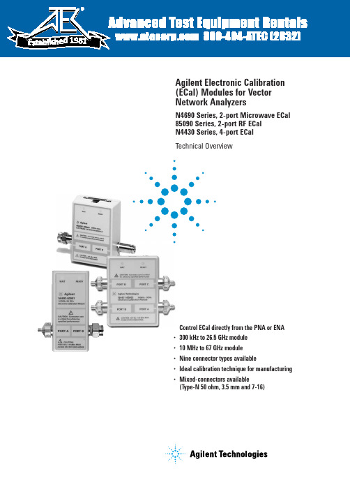
•Control ECal directly from the PNA or ENA •300 kHz to 26.5 GHz module •10 MHz to 67 GHz module •Nine connector types available•Ideal calibration technique for manufacturing •Mixed-connectors available(Type-N 50 ohm, 3.5 mm and 7-16)Agilent Electronic Calibration (ECal) Modules for Vector Network AnalyzersN4690 Series, 2-port Microwave ECal 85090 Series, 2-port RF ECal N4430 Series, 4-port ECalTechnical Overview198125. ENA series consists of E5070/1.6. ENA-L series consists of E5061/2.7.N3381/2/3 have been discontinued.8. PNA-L series consists of N5230.ECal and Agilent Network Analyzer ConfigurationsPNA and ENA SeriesECal modules are controlled directly from the PNA and ENA Series network analyzers. No external PC is required. Simply connect the ECal module to the USB port on the network analyz-er. You can control your calibra-tion from the front panel keys of the PNA Series or automatically by your user program.Calibration configuration using the PNA series3Perform adapter removal calibrations fasterSome analyzers, such as later versions of the 8753 and 8720, offer adapter removal calibration for non-insertable and mixed connector measurement capabil-ity. Since this method requires two full two-port calibrations, it is often time consuming and prone to operator errors. Using ECal to perform the two-port calibrations addresses both of these concerns by reducing the calibration time and the number of connections, simplifying the overall adapter removal process.Perform a User-characterization Normally, when you perform a calibration with an ECal module, the error terms for a calibration are computed using the factory characterization (data) stored in the module. User-characteriza-tion allows you to change the characterization of the module in two ways:• Change the connector configuration: allows you to add an adapter or fixture to the test port of the module and embed the effects into the characterization of the module. The result of the new characterization extends the reference plane from one or more of the module’s test ports to those on the adapter (or fixture).• Modify the state settings: allows you to specify the number of data points (1601 maximum) or other stimulus settings the module uses to perform a cali-bration.When you perform a user-charac-terization, the factory characteri-zation data remains stored in the module’s memory. At calibration, you can select the factory characterization or any of the user-defined characterizations stored in the module. The module can store up to five user-defined characterizations (in addition to the factory characterization data). User-characterization is available with PNA and ENA Series Network Analyzers.41. If the maximum input power is exceeded when calibrating, compression may occur.2. When using the PNA-X, the power level can be increased after calibration with minimal impact on measurement accuracy.3. When mated with male connectors with a 0.77 mm (0.030 in) to 0.86 mm (0.034 in) pin diameter51. When applied power exceeds +9 dBm, calibration results will be degraded from the performance indicated in the table.2. When applied power exceeds –5 dBm, calibration results will be degraded from the performance indicated in the table.3. 3.5 mm modules have precision slotless connectors that guarantee the best calibration accuracy is transferred to your system.61.When applied power exceeds +9 dBm, calibration results will be degraded from the performance indicated in the table.2. When applied power exceeds –5 dBm, calibration results will be degraded from the performance indicated in the table.73. Performance from 9 kHz to 300 kHz is valid only for the E5071C ENA network analyzer with firmware version A.09.10 or higher.4. 9 to 13.5 GHz range not vaild for the N4431A81. When applied power exceeds –7 dBm, calibration results will be degraded from the performance indicated in this table.2. Values based on using the PNA Network Analyzer N5230A Option 240 or 245910Ordering informationSelect an ECal module based on the connector type required and the frequency range of your vector network analyzer (refer to table below).OptionsOption Description00F Replace f-m connectors on ECal module(s) with f-f connectors 00M Replace f-m connectors on ECal module(s) with m-m connectors00A Adds male-to-male and female-to-female adapters (also adds a 5/16” 90 N-cm (8 in-lb) torque wrench to 3.5 mm modules)1A7ISO 17025 compliant calibration A6J ANSI Z540 compliant calibrationUK6Commercial calibration certificate with measured data M0F f-m connectors on ECal module(s)010Four female, 3.5 mm connectors 020Four female, Type-N 50 ohm connectorsECal modules and available options2-portConnector Frequency range ECal module Available options Type model number Type-F300 kHz to 3 GHz85099C 00A, 00F, 00M, UK6, M0FType-N 300 kHz to 9 GHz 85092C00A, 00F, 00M, UK6, 1A7, A6J, M0F,50 ohms mixed-connectorsType-N 300 kHz to 18 GHz N4690B00A, 00F, 00M, UK6, 1A7, A6J, M0F 50 ohmsType-N 300 kHz to 3 GHz 85096C 00A, 00F, 00M, UK6, M0F75 ohms3.5 mm 300 kHz to 9 GHz85093C00A, 00F, 00M, UK6, 1A7, A6J, M0F mixed connectors3.5 mm 300 kHz to 26.5 GHz N4691B 00A, 00F, 00M, UK6, 1A7, A6J, M0F 7 mm 300 kHz to 9 GHz 85091C UK6, 1A7, A6J 7 mm 300 kHz to 18 GHz N4696BUK6, 1A7, A6J7-16 300 kHz to 7.5 GHz 85098C 00A, 00F, 00M, UK6, M0F, mixed-connectors 2.92 mm 10 MHz to 40 GHz N4692A 00A,00F, 00M, UK6, 1A7, A6J, M0F 2.4 mm 10 MHz to 50 GHz N4693A 00A,00F, 00M, UK6, 1A7, A6J, M0F 1.85 mm10 MHz to 67 GHzN4694A00A,00F, 00M, UK6, 1A7, A6J, M0F4-portConnector Frequency range ECal module Available options Type model number 3.5 mm or 9 kHz to 13.5 GHz N4431B010, 020, UK6, 1A7, A6J, mixed-connectorsType-N 50 ohms Type-N 300 kHz to 18 GHz N4432A 020, mixed-connectors 50 ohms 3.5 mm300 kHz to 20 GHzN4433A010Notes:1. Order the 85097B interface module if you will be using ECal with your 8719, 8720, 8722 or 8753. (Please reference the ECal and network analyzer/firmware compatibility table on page 3.) The 85097B con-sists of an interface module and a power supply.2.When using the N469x ECal prod-ucts with the 8720 or 8753 network analyzer families, an adapter cable (8121-1047) is needed. This adapter cable is orderable as an option with the 85097B.1.Performance from 9 kHz to 300 KHz is valid only for the E5071C ENA network analyzer with firmware version A.09.10 or higher.1111.Limits ECal module high frequency to 7.5 GHz.Remove all doubtOur repair and calibration services will get your equipment back to you, performing like new, when prom-ised. You will get full value out of your Agilent equipment through-out its lifetime. Your equipment will be serviced by Agilent-trained technicians using the latest factory calibration procedures, automated repair diagnostics and genuine parts. You will always have the utmost confidence in your measurements. For information regarding self maintenance of this product, please contact your Agilent office.Agilent offers a wide range of ad-ditional expert test and measure-ment services for your equipment, including initial start-up assistance, onsite education and training, as well as design, system integration, and project management.For more information on repair and calibration services, go to:/find/removealldoubt/find/emailupdatesGet the latest information on theproducts and applications you select./find/agilentdirectQuickly choose and use your testequipment solutions with confidence./find/openAgilent Open simplifies the process of connecting and programming test systems to help engineers design, validate and manufacture electronic products. Agilent offers open connectivity for a broad range of system-ready instruments, open industry software, PC-standard I/O and global support, which are combined to more easily integrate test system development.For more information on Agilent Technol-ogies’ products, applications or services, please contact your local Agilent office. The complete list is available at:/find/contactus Americas Canada(877) 894-4414Latin America 305 269 7500United States (800) 829-4444Asia Pacific Australia 1 800 629 485China800 810 0189Hong Kong 800 938 693India 1 800 112 929Japan 0120 (421) 345Korea 080 769 0800Malaysia 1 800 888 848Singapore 180****8100Taiwan 0800 047 866Thailand1 800 226 008Europe & Middle East Austria 01 36027 71571Belgium 32 (0) 2 404 93 40 Denmark 45 70 13 15 15Finland 358 (0) 10 855 2100France 0825 010 700**0.125 €/minuteGermany ************Ireland 1890 924 204Israel 972-3-9288-504/544Italy 39 02 92 60 8484Netherlands 31 (0) 20 547 2111Spain 34 (91) 631 3300Sweden 0200-88 22 55Switzerland 0800 80 53 53United Kingdom 44 (0) 118 9276201Other European Countries:/find/contactusRevised: October 6, 2008© Agilent Technologies, Inc. 2002-2009Printed in USA, February 3, 20095963-3743EWindows ®and Windows NT ®are U.S. registered trademarks of Microsoft Corp.Product specifications and descriptions in this document subject to change without notice.Web ResourcesVisit our Web sites, for additional product information and literature.Electronic calibration (ECal):/find/ecalPNASeries network analyzers:/find/pnaTest and measurement accessories:/find/accessories。
Agilent N432A Thermistor Power Meter 数据手册说明书

Agilent N432AThermistor Power MeterData SheetAgilent’s only power meter that supports thermistor mount with useful enhancements for metrology and calibration lab environments.Why Agilent’s Power Meters and Sensors?Reliable, high-performing solutionsEvery power meter and sensor from Agilent consistently delivers great results.A sure investment for many years to comeCode-compatibility between power meters reduces the need for re-coding. Notonly that, all Agilent power meters are backward-compatible with most legacypower sensors.One specific application: One right solutionAgilent offers a wide selection of power meters and sensors for practicallyall application needs—wireless communications, radar pulse measurements,component test, and more.Global network supportNo matter where you are, Agilent is committed to giving you the 24-hoursupport you need regarding our products, applications, or services.Agilent’s power meters have long beenrecognized as the industry standard forRF and microwave power measurements.We Listened to the Industry, Then Delivered a Better and Easier Replacement Solution for the Legacy 432A Analog Power MeterAs today’s power measurements become more complex, it is increas-ingly difficult to make reliable, accu-rate power measurements. For more than 40 years, you’ve depended on Agilent’s 432A analog power meter, used with temperature compensated thermistor sensors to provide high accuracy over a wide temperaturerange. LXI Class-C compliant N432AThe N432A is a single-channel, aver-age RF power measurement meter that supports thermistor sensors. The N432A has the capability to measure and display average power, RF bridge voltages (V RF0 and V RF1), compensation bridge voltages (V COMP0 and V COMP1), V 0, and V 1. It is also provided with a set of features such as zeroing and a built-in self-test.Developed using LXI technology, the N432A is an LXI Class-C compli-ant instrument.1 The N432A basic configuration consists of two key sections: bridge and meter logic. When a compatible thermistor sensor is connected to the N432A, the RF and compensation bridge circuits are formed in the bridge section. V RF , which is the voltage at the top of the RF bridge, is responsive to both input RF power and ambient temperature changes. On the other hand, V COMP , which is the voltage at the top of the compensation bridge, is responsive only to ambient temperature changes. The V RF and V COMP values are used in calculating the RF power. Meanwhile, the meter logic section processes V RF and V COMP to produce a meter current proportional to RF power.In general, the N432A is an easy-to-use instrument, especially with the availability of an integrated Web browser that provides a con-venient way to view and modify the instrument network configuration. Besides the LAN interface, the N432A also supports industry standard GPIB and USB interfaces for measurement automation.Today, the Agilent N432A digital thermistor power meter, loaded with enhancements, including a color digital display, and intuitive front panel interface will continue support your measurement needs with greater capability and expanded functionality. Best of all, you can get these extras at just a fraction of the price of the legacy 432A.1. LXI, an acronym for LAN eXtension for Instrumentation, is an instrument standard for devices that use the Ethernet (LAN) as their primarycommunication interface.High accuracy—no thermoelectric errorThe high accuracy ± (0.1% of reading + 0.5 μW) over a wide temperature range featured in the legacy 432A power meter is also included in the N432A, making it excellent for 1 mW transfer calibration (with 478A-H75/ H76*). Accuracy can be maintained on even the most sensitive range as the error due to thermoelectric effect is reduced to a negligible level.* 478-H75/H76 has a maximum SWR of1.05 at 50 MHz Sensor compatibilityThe N432A is compatible with the Agilent 478A and 8478B thermistor sensors. The following table lists the frequency range and operating resistance for these two sensors:478A0.01 to 10200478A Option H630.000001 to 1200478A Option H750.001 to 1200478A Option H760.001 to 12008478B0.01 to 18200For further information on the thermistor sensors, refer to the respective manuals.Take a Closer Look N432A front panel N432A back panelHigh-resolution color LCD display for easy viewing of test results Display key allows selection of the display format for the active window (single/split screen)Display key allows selection of the display mode (windowed, expanded, or full-screen) of numeric measurements Hard keys provide quick access to the most frequently used functions, such as System, Trigger, and Acquisition, etc.Channel sensor connectorArrow keys enable navigation of parameter entry screens, values selection, and entering of text Soft keys provide menu selection Numeric keypad for easy entry of numeric values Power reference of 1 mW (0 dBm)Ground connectorDC recorder outputs (DC voltage corresponds to the power level of the channel input)V RF and V COMP output terminals for calibrating the N432A and for precision power measurements Line power accepts voltage with automatic range selectionGo beyond GPRB with USB and LAN/LXI-C interfaceSpecifications and CharacteristicsSpecifications describe the instrument’s warranted performance and apply after a 30 minute warm-up.These specifications are valid over its operating/environmental range unless otherwise stated and after performing a zero and calibration procedure.Supplemental characteristics (shown in italics) are intended to provide additional information, useful in applying the instru-ment by giving typical (expected), but not warranted performance parameters. These characteristics are shown in italics or labeled as “typical”, “nominal” or “approximate”.Frequency range100 kHz to 18 GHz, sensor dependent Power range–30 to +10 dBm (1 μW to 10 mW), thermistor-sensor dependent Compatible power sensors• Agilent 478A thermistor sensor (100 kHz to 10 GHz, with option H63)• Agilent 8478B thermistor sensor (10 MHz to 18 GHz)Meter power accuracy Power absolute accuracy± (0.1% of reading + 0.5 μW)Meter voltage accuracy (1-year reference specifications) V RF and V COMP V 0 and V 1 23 °C ± 5 °C: ± (0.0035% + 50 μV) [reading + range] 23 °C ± 5 °C: ± (0.0040% + 25 μV) [reading + range]Bridge resistance100, 200, 300, or 400 Ω (user selectable)Display units Power Relative V RF , V COMP , V 0, and V 1 Bridge resistanceWatts (W) or dBm Percent (%) or dB VDC and mVDC Ohm Display resolution PowerDefault resolution Voltage Bridge resistance Selectable resolution of: 1.0, 0.1, 0.01 and 0.001 dB in logarithmic mode, or 1, 2, 3, and 4 significant digits in linear mode 0.01 dB in logarithmic mode or three digits in linear mode 6.5-digit resolution 6.5-digit resolutionAccessed by key entry Either hard keys, or soft key menu, and programmableZero Zeros the meter. (Power reference calibrator is switched off during zeroing)Frequency Entered frequency range is used to interpolate the calibration factors table. Frequency range from1 kHz to 999.9 GHzBridge resistance type Setting the bridge resistance, user-selectable Rmeasure (factory set) or Ruser (measured by user) Cal factor Sets the cal factor versus frequency for the calibration factor for power sensor. Range: 1.00% to150.00%, in 0.01% increments. Cal factor can be set from either CF table or single entry CF Relative Displays all successive measurements relative to the last displayed valueOffset Allows power measurements to be offset by –100 to +100 dB, settable in 0.001dB increments, tocompensate for external loss or gain. Offset table can be set from either CF table or single entryCFSave/recall Store up to 10 instrument states via the save/recall menuMeasurement averaging Selectable from 4 to 128Duty cycle Duty cycle values between 0.001 to 99.999%, in 0.001% increments, can be entered to display apeak power representation of measured power. The following equation is used to calculate thedisplayed peak power value: peak power = measured power/duty cycleLimits High and low limits can be set in the range –150.000 to +230.000 dBm, in 0.001 dBm increments Preset default values dBm mode, relative off, power reference off, duty cycle off, offset off, frequency 50 MHz,measurement averaging 16, free runDisplay Color display with selectable single and split screen formats are available. User selectable ondigital measurement type or analog scale presentation1 mW (0 dBm) power reference Accuracy (for two years)SWR 1.0 mW (0.0 dBm), 50 MHz from type N (f) connector on the front panel, for power meter/sensor function check.± 0.4% (25 ± 10 ºC)± 1.2% (0 to 45 ºC)1.05 (typical),1.08 (0°C to 45°C)Dimensions The following dimensions excludefront and rear protrusions:212.6 mm W x 88.5 mm H x 348.3 mm D(8.5 in x 3.5 in x 13.7 in)Weight Model Net ShippingN432A 3.6 kg (8.0 lb) 8.2 kg (18.1 lb) Rear panel connectorsV RF output VRFBNC terminal outputs the RF bridge voltage, used to connect to external DMM for moreprecise power measurementV COMP output VCOMPBNC terminal outputs the compensation bridge voltage, used to connect to externalDMM for more precise power measurementRecorder output Analog 0 to 1 V, 1 kΩ output impedance, BNC connector GPIB, USB 2.0 and 10/100BaseT LAN Interfaces to allow communication with an external controller Ground Binding post, accepts 4 mm plug or bare wire connectionLine powerInput voltage range Input frequency range 100 – 240 VAC, automatic selection 220 – 240 V ±10%50 – 60 Hz, 400 Hz400 Hz (100 – 120 Vac)Power requirement70 VAElectromagnetic compatibility Complies with the essential requirements of EMC Directive (2004/108/EC) as follows:• IEC61326-1:2005 / EN61326-1:2006• CISPR11:2003 / EN55011:2007 (Group 1, Class A)The product also meets the following EMC standards:• Canada: ICES/NMB-001:2004• Australia/New Zealand: AS/NZS CISPR 11:2004Product safety This product conforms to the requirements of the following safety standards:• IEC 61010-1:2001 / EN 61010-1:2001• CAN/CSA-C22.2 No.61010-1-04• ANSI/UL61010-1:2004Low voltage directive This product conforms to the requirements of European Council Directive “2006/95/EC”Operating environment Temperature Maximum humidity Minimum humidity Maximum altitude 0 °C to 45 °C95% at 40 °C (non-condensing) 15% at 40 °C (non-condensing) 4,600 m (15,000 ft)Storage conditionsNon-operating storage temperature Non-operating maximum humidity Non-operating maximum altitude –40 °C to +70 °C90% at 65 °C (non-condensing) 4,600 m (15,000 ft)Remote programming Interface Command language GPIB compatibility GPIB, USB, and LAN interfaces operates to IEEE 488.2 standard SCPI standard interface commandsSH1, AH1, T6, TE0, L4, LE0, SR1, RL1, PP1, DC1, DT1, C0Ordering InformationN432A Thermistor power meterStandard shipped accessories• Thermistor sensor adaptor cable 1.5 m* (5 ft)• Power cord (country dependant)• USB adaptor cable• Agilent N432A thermistor power meter product reference CD-ROM• Envelope—calibration certificate• IO libraries media suiteWarranty• Standard 3-year, return-to-Agilent warranty and service plan• 3 months for standard shipped accessoriesfrequency points Standard Lab calibration478A-H55Frequency range 1 MHz to 1 GHz, with maximum SWR 1.3478A-H63Frequency range 100 kHz to 1 GHz, max SWR 1.8 to 300 kHz, 1.3 to 1 GHz478A-H72Frequency range 1 MHz to 1 GHz, with maximum SWR 1.2478A-H73Frequency range 1 MHz to 100 MHz, with maximum SWR 1.1, except 1.05 at 50 MHz478A-H75Frequency range 1 MHz to 1 GHz, max SWR 1.3 except 1.05 at 50 MHz478A-H76Frequency range 1 MHz to 1 GHz, max SWR 1.3 except 1.05 at 50 MHz. Standard lab calibration at50 MHz478A-H83Frequency range 1 MHz to 1 GHz, with maximum SWR 1.3, except 1.05 at 50 MHz Include 8frequency points Standard Lab calibration478A-H93Frequency range 1 MHz to 1 GHz, with maximum SWR 1.3, except 1.05 at 50 MHz Include 2frequency points Standard Lab calibration8478B-H01Frequency range 10 MHz to 18 GHz, with maximum SWR 1.05 at 50 MHz8478B-H27Frequency range 10 MHz to 18 GHz. Include Standard Lab calibration at 9 MHzN4998A Thermistor sensor adaptor cable 1.5 m (5 ft)N4998B Thermistor sensor adaptor cable 3 m (10 ft)N4998C Thermistor sensor adaptor cable 6.1 m (20 ft)N432A-908Rackmount kit with 1 unit with blank filler includedN432A-909Rackmount kit with 2 units side-by-sideN432A-OBK English language user guide and English programming guideN432A-ABJ Japanese user guide and English programming guideN432A-0B1English language user guide and installation guideN432A-0BF English language programming guideN432A-A6J Certificate of compliance calibration - ANSI/NCSL Z540N432A-1A7Compliant calibration test data - ISO17025* The 1.5 m (5 ft) standard cable can be replaced with a 3 or 6.1 m (10 or 20 ft) cable, charges applyAdvancedTCA ® Extensions for Instrumentation and Test (AXIe) is an open standard that extends the AdvancedTCA for general purpose and semiconductor test. Agilent is a founding member of the AXIe consortium. LAN eXtensions for Instruments puts the power of Ethernet and the Web inside your test systems. Agilent is a founding member of theLXI PCI eXtensions for Instrumentation (PXI) modular instrumentation delivers a rugged, PC-based high-performance measurement and automation system.Three-Year Warranty /find/ThreeYearWarranty Beyond product specification, changing the ownership experience. Agilent is the only test and measurement company that offers three-year warranty on all instruments, worldwide.Agilent Assurance Plans /find/AssurancePlans Five years of protection and no budgetary surprises to ensure your instruments are operating to specifications and you cancontinually rely on accurate /quality Agilent Electronic Measurement Group DEKRA Certified ISO 9001:2008 Quality Management System Agilent Channel Partners /find/channelpartners Get the best of both worlds: Agilent’s measurement expertise and product breadth, combined with channel partner /find/N432AFor more information on Agilent Technologies’ products, applications or services, please contact your local Agilent office. The complete list is available at:/find/contactusAmericasCanada Brazil Mexico United States(877) 894 4414 (11) 4197 360001800 5064 800 (800) 829 4444Asia PacificAustralia China Hong Kong India Japan Korea Malaysia Singapore Taiwan Other AP Countries1 800 629 485800 810 0189800 938 6931 800 112 9290120 (421) 345080 769 08001 800 888 848180****81000800 047 866(65) 375 8100Europe & Middle EastBelgium Denmark Finland FranceGermany Ireland Israel Italy Netherlands Spain Sweden United Kingdom32 (0) 2 404 93 40 45 45 80 12 15358 (0) 10 855 21000825 010 700**0.125 €/minute 49 (0) 7031 464 6333 1890 924 204972-3-9288-504/54439 02 92 60 848431 (0) 20 547 211134 (91) 631 33000200-88 22 5544 (0) 118 927 6201For other unlisted countries:/find/contactus (BP-01-15-15)Product specifications and descriptions in this document subject to change without notice.© Agilent Technologies, Inc. 2013, 2014Published in USA, February 24, 20145990-5740EN。
安捷伦仪器使用说明书中文

Alpha安捷伦B1500A半导体器件分析仪用户!ˉ的GUID安捷伦科技公司声明?安捷伦科技公司2005年,2006年,2007年,2008本手册的任何部分不得转载任何形式或通过任何手段(包括电子电子存储和检索或翻译成外国语言)事先同意MENT和安捷伦的书面同意作为由美国科技公司在美国和国际版权法。
手册部件号B1500-90000版2005年7月第1版,第2版,2005年12月2006年4月第3版第4版,2007年1月2007年6月5日,版第6版,2007年11月2008年10月7日,版安捷伦科技公司5301史蒂文斯溪大道95051美国加利福尼亚州圣克拉拉保证本文档中所含的物质是提供MENT!°为是,±,是苏如有更改,恕不另行通知,在以后的版本。
此外,最大而且,在适用法律法律,安捷伦提供任何保证,明示或暗示,关于本手册的任何信息所载,包括但不不限于隐含保证为杆的适销性和适用性特定用途。
安捷伦不得承担错误或偶然或在相应的损害赔偿连接TION的家具,使用,或每本文件或任何性能所载资料。
应该安捷伦与用户有一个单独的与保修的书面协议在这个物质的范围,涵盖记录与这些冲突条款,在保修则以协议arate中的协议为准。
技术许可硬件和/或软件描述这份文件是依照许可可用于复制或只在雅跳舞的许可条款。
有限权利如果软件在使用的一种表现美国政府的首要合同或道,软件交付和许可!°商业计算机软件!±ADFAR252.227-7014(1995年6月)的定义,或作为一个!°商业项目!FA±定义2.101(a)或°有限计算机软!洁具!±作为定义在FAR52.227-19(六月1987)或任何相当机构法规或合同条款。
使用,重复或disclo的软件肯定是受安捷伦科技nologies!ˉ标准商业许可条款和非DOD部门和美国政府机构没有获得更大而不是限制权利定义在FAR 52.227-19中(C)(1-2)(6月1987年)。
Agilent Technologies PSA 和 ESA 系列光谱分析仪一键测量功能指南说明书
User’s and Programmer’s ReferenceVolume 2One-Button Power Measurements PSA and ESA Series Spectrum Analyzers Refer to Volume 1 for core spectrum analyzer information.This manual provides documentation for the following instruments:Agilent Technologies PSA SeriesE4443A (3 Hz - 6.7 GHz)E4445A (3 Hz - 13.2 GHz)E4440A (3 Hz - 26.5 GHz)E4447A (3 Hz - 42.98 GHz)E4446A (3 Hz - 44.0 GHz)E4448A (3 Hz - 50.0 GHz)Agilent Technologies ESA-E SeriesE4402B (9kHz - 3.0GHz)E4404B (9kHz - 6.7GHz)E4405B (9kHz - 13.2GHz)E4407B (9kHz - 26.5GHz)Agilent Technologies ESA-L SeriesE4411B (9kHz- 1.5GHz)E4403B (9kHz - 3.0GHz)E4408B (9kHz - 26.5GHz)Manufacturing Part Number: E4440-90618Supersedes: E4440-90346Printed in USAMarch 2014© Copyright 1999-2014 Agilent Technologies, Inc..Legal InformationThe information contained in this document is subject to change without notice.Agilent Technologies makes no warranty of any kind with regard to this material, including but not limited to, the implied warranties of merchantability and fitness for a particular purpose. Agilent Technologies shall not be liable for errors contained herein or for incidental or consequential damages in connection with the furnishing, performance, or use of this material.Where to Find the Latest InformationDocumentation is updated periodically.•For the latest information about Agilent Technologies PSA Spectrum Analyzers, including firmware upgrades and application information, please visit the following Internet URL:/find/psa•For the latest information about Agilent Technologies ESA Spectrum Analyzers, including firmware upgrades and application information, please visit the following Internet URL:/find/esa•To receive the latest updates by email, subscribe to Agilent Email Updates:/find/emailupdates•Information on preventing spectrum analyzer damage can be found at:/find/tips21. Using This DocumentAbout the User’s and Programmer’s Information. . . . . . . . . . . . . . . . . . . . . . . . . . . . . . . . . . . . . . . . . . . . . 26 What is in This Book. . . . . . . . . . . . . . . . . . . . . . . . . . . . . . . . . . . . . . . . . . . . . . . . . . . . . . . . . . . . . . . . . 26 Terms Used in This Book . . . . . . . . . . . . . . . . . . . . . . . . . . . . . . . . . . . . . . . . . . . . . . . . . . . . . . . . . . . . . 27 2. One-Button Measurement FunctionsOne - Button Measurement Functions . . . . . . . . . . . . . . . . . . . . . . . . . . . . . . . . . . . . . . . . . . . . . . . . . . . . . 30 Mode Setup (Spectrum Analysis Mode) . . . . . . . . . . . . . . . . . . . . . . . . . . . . . . . . . . . . . . . . . . . . . . . . . . . 33 Radio Std. . . . . . . . . . . . . . . . . . . . . . . . . . . . . . . . . . . . . . . . . . . . . . . . . . . . . . . . . . . . . . . . . . . . . . . . . . 33 Radio Std Setup. . . . . . . . . . . . . . . . . . . . . . . . . . . . . . . . . . . . . . . . . . . . . . . . . . . . . . . . . . . . . . . . . . . . . 45 Retain Params . . . . . . . . . . . . . . . . . . . . . . . . . . . . . . . . . . . . . . . . . . . . . . . . . . . . . . . . . . . . . . . . . . . . . . 47 Enable All Measurements. . . . . . . . . . . . . . . . . . . . . . . . . . . . . . . . . . . . . . . . . . . . . . . . . . . . . . . . . . . . . 47 Autorange of Power Setting (Remote command only). . . . . . . . . . . . . . . . . . . . . . . . . . . . . . . . . . . . . . . 48 MEASURE (Spectrum Analysis Mode) . . . . . . . . . . . . . . . . . . . . . . . . . . . . . . . . . . . . . . . . . . . . . . . . . . . 49 Command Interactions: MEASure, CONFigure, FETCh, INITiate and READ. . . . . . . . . . . . . . . . . . . . 50 Current Measurement Query (Remote Command Only) . . . . . . . . . . . . . . . . . . . . . . . . . . . . . . . . . . . . . 53 Test Current Results Against all Limits (Remote Command Only) . . . . . . . . . . . . . . . . . . . . . . . . . . . . . 53 Meas Off . . . . . . . . . . . . . . . . . . . . . . . . . . . . . . . . . . . . . . . . . . . . . . . . . . . . . . . . . . . . . . . . . . . . . . . . . . 54 Channel Power . . . . . . . . . . . . . . . . . . . . . . . . . . . . . . . . . . . . . . . . . . . . . . . . . . . . . . . . . . . . . . . . . . . . . 54 Occupied BW . . . . . . . . . . . . . . . . . . . . . . . . . . . . . . . . . . . . . . . . . . . . . . . . . . . . . . . . . . . . . . . . . . . . . . 57 Adjacent Channel Power—ACP. . . . . . . . . . . . . . . . . . . . . . . . . . . . . . . . . . . . . . . . . . . . . . . . . . . . . . . . 58 Multi-Carrier Power . . . . . . . . . . . . . . . . . . . . . . . . . . . . . . . . . . . . . . . . . . . . . . . . . . . . . . . . . . . . . . . . . 62 Power Stat CCDF . . . . . . . . . . . . . . . . . . . . . . . . . . . . . . . . . . . . . . . . . . . . . . . . . . . . . . . . . . . . . . . . . . . 64 Harmonic Distortion . . . . . . . . . . . . . . . . . . . . . . . . . . . . . . . . . . . . . . . . . . . . . . . . . . . . . . . . . . . . . . . . . 67 Burst Power . . . . . . . . . . . . . . . . . . . . . . . . . . . . . . . . . . . . . . . . . . . . . . . . . . . . . . . . . . . . . . . . . . . . . . . 70 Intermod (TOI) . . . . . . . . . . . . . . . . . . . . . . . . . . . . . . . . . . . . . . . . . . . . . . . . . . . . . . . . . . . . . . . . . . . . . 73 Spurious Emissions . . . . . . . . . . . . . . . . . . . . . . . . . . . . . . . . . . . . . . . . . . . . . . . . . . . . . . . . . . . . . . . . . 74 Spectrum Emission Mask . . . . . . . . . . . . . . . . . . . . . . . . . . . . . . . . . . . . . . . . . . . . . . . . . . . . . . . . . . . . . 75 Meas Setup (Adjacent Channel Power—ACP) . . . . . . . . . . . . . . . . . . . . . . . . . . . . . . . . . . . . . . . . . . . . . . 83 Avg Number . . . . . . . . . . . . . . . . . . . . . . . . . . . . . . . . . . . . . . . . . . . . . . . . . . . . . . . . . . . . . . . . . . . . . . . 83 Avg Mode . . . . . . . . . . . . . . . . . . . . . . . . . . . . . . . . . . . . . . . . . . . . . . . . . . . . . . . . . . . . . . . . . . . . . . . . . 84 Chan Integ BW . . . . . . . . . . . . . . . . . . . . . . . . . . . . . . . . . . . . . . . . . . . . . . . . . . . . . . . . . . . . . . . . . . . . . 84 Offset/Limits. . . . . . . . . . . . . . . . . . . . . . . . . . . . . . . . . . . . . . . . . . . . . . . . . . . . . . . . . . . . . . . . . . . . . . . 85 Meas Type . . . . . . . . . . . . . . . . . . . . . . . . . . . . . . . . . . . . . . . . . . . . . . . . . . . . . . . . . . . . . . . . . . . . . . . . 89 Optimize Ref Level . . . . . . . . . . . . . . . . . . . . . . . . . . . . . . . . . . . . . . . . . . . . . . . . . . . . . . . . . . . . . . . . . 90 Method . . . . . . . . . . . . . . . . . . . . . . . . . . . . . . . . . . . . . . . . . . . . . . . . . . . . . . . . . . . . . . . . . . . . . . . . . . . 91 Total Pwr Ref . . . . . . . . . . . . . . . . . . . . . . . . . . . . . . . . . . . . . . . . . . . . . . . . . . . . . . . . . . . . . . . . . . . . . . 94 PSD Ref. . . . . . . . . . . . . . . . . . . . . . . . . . . . . . . . . . . . . . . . . . . . . . . . . . . . . . . . . . . . . . . . . . . . . . . . . . . 95 Limit Test . . . . . . . . . . . . . . . . . . . . . . . . . . . . . . . . . . . . . . . . . . . . . . . . . . . . . . . . . . . . . . . . . . . . . . . . . 96 RRC Filter . . . . . . . . . . . . . . . . . . . . . . . . . . . . . . . . . . . . . . . . . . . . . . . . . . . . . . . . . . . . . . . . . . . . . . . . 96 Filter Alpha . . . . . . . . . . . . . . . . . . . . . . . . . . . . . . . . . . . . . . . . . . . . . . . . . . . . . . . . . . . . . . . . . . . . . . . 97 Noise Correction . . . . . . . . . . . . . . . . . . . . . . . . . . . . . . . . . . . . . . . . . . . . . . . . . . . . . . . . . . . . . . . . . . . 97 Trace/View (ACP Measurement) . . . . . . . . . . . . . . . . . . . . . . . . . . . . . . . . . . . . . . . . . . . . . . . . . . . . . . . . . 99 Spectrum . . . . . . . . . . . . . . . . . . . . . . . . . . . . . . . . . . . . . . . . . . . . . . . . . . . . . . . . . . . . . . . . . . . . . . . . . . 99 Bar Graph . . . . . . . . . . . . . . . . . . . . . . . . . . . . . . . . . . . . . . . . . . . . . . . . . . . . . . . . . . . . . . . . . . . . . . . . . 99 Combined . . . . . . . . . . . . . . . . . . . . . . . . . . . . . . . . . . . . . . . . . . . . . . . . . . . . . . . . . . . . . . . . . . . . . . . . 100 Combined View Units. . . . . . . . . . . . . . . . . . . . . . . . . . . . . . . . . . . . . . . . . . . . . . . . . . . . . . . . . . . . . . . 100 Trace . . . . . . . . . . . . . . . . . . . . . . . . . . . . . . . . . . . . . . . . . . . . . . . . . . . . . . . . . . . . . . . . . . . . . . . . . . . . 100 Meas Setup (Burst Power) . . . . . . . . . . . . . . . . . . . . . . . . . . . . . . . . . . . . . . . . . . . . . . . . . . . . . . . . . . . . . 1013Avg Number . . . . . . . . . . . . . . . . . . . . . . . . . . . . . . . . . . . . . . . . . . . . . . . . . . . . . . . . . . . . . . . . . . . . . . 101 Avg Mode . . . . . . . . . . . . . . . . . . . . . . . . . . . . . . . . . . . . . . . . . . . . . . . . . . . . . . . . . . . . . . . . . . . . . . . . 102 Average Type . . . . . . . . . . . . . . . . . . . . . . . . . . . . . . . . . . . . . . . . . . . . . . . . . . . . . . . . . . . . . . . . . . . . . 103 Threshold Lvl . . . . . . . . . . . . . . . . . . . . . . . . . . . . . . . . . . . . . . . . . . . . . . . . . . . . . . . . . . . . . . . . . . . . . 103 Meas Method . . . . . . . . . . . . . . . . . . . . . . . . . . . . . . . . . . . . . . . . . . . . . . . . . . . . . . . . . . . . . . . . . . . . . 104 Burst Width. . . . . . . . . . . . . . . . . . . . . . . . . . . . . . . . . . . . . . . . . . . . . . . . . . . . . . . . . . . . . . . . . . . . . . . 104 Optimize Ref Level. . . . . . . . . . . . . . . . . . . . . . . . . . . . . . . . . . . . . . . . . . . . . . . . . . . . . . . . . . . . . . . . . 106 Trace/View (Burst Power) . . . . . . . . . . . . . . . . . . . . . . . . . . . . . . . . . . . . . . . . . . . . . . . . . . . . . . . . . . . . . 107 RF Envelope. . . . . . . . . . . . . . . . . . . . . . . . . . . . . . . . . . . . . . . . . . . . . . . . . . . . . . . . . . . . . . . . . . . . . . 107 Combined . . . . . . . . . . . . . . . . . . . . . . . . . . . . . . . . . . . . . . . . . . . . . . . . . . . . . . . . . . . . . . . . . . . . . . . . 108 Trace . . . . . . . . . . . . . . . . . . . . . . . . . . . . . . . . . . . . . . . . . . . . . . . . . . . . . . . . . . . . . . . . . . . . . . . . . . . . 108 Meas Setup (Complementary Cumulative Distribution Function—CCDF) . . . . . . . . . . . . . . . . . . . . . . . 109 Meas BW . . . . . . . . . . . . . . . . . . . . . . . . . . . . . . . . . . . . . . . . . . . . . . . . . . . . . . . . . . . . . . . . . . . . . . . . 109 Counts . . . . . . . . . . . . . . . . . . . . . . . . . . . . . . . . . . . . . . . . . . . . . . . . . . . . . . . . . . . . . . . . . . . . . . . . . . 110 Meas Interval . . . . . . . . . . . . . . . . . . . . . . . . . . . . . . . . . . . . . . . . . . . . . . . . . . . . . . . . . . . . . . . . . . . . . 111 Optimize Ref Level . . . . . . . . . . . . . . . . . . . . . . . . . . . . . . . . . . . . . . . . . . . . . . . . . . . . . . . . . . . . . . . . 112 Display (Complementary Cumulative Distribution Function—CCDF). . . . . . . . . . . . . . . . . . . . . . . . . . . 113 Full Screen . . . . . . . . . . . . . . . . . . . . . . . . . . . . . . . . . . . . . . . . . . . . . . . . . . . . . . . . . . . . . . . . . . . . . . . 113 Store Ref Trace. . . . . . . . . . . . . . . . . . . . . . . . . . . . . . . . . . . . . . . . . . . . . . . . . . . . . . . . . . . . . . . . . . . . 113 Ref Trace. . . . . . . . . . . . . . . . . . . . . . . . . . . . . . . . . . . . . . . . . . . . . . . . . . . . . . . . . . . . . . . . . . . . . . . . . 113 Gaussian Trace . . . . . . . . . . . . . . . . . . . . . . . . . . . . . . . . . . . . . . . . . . . . . . . . . . . . . . . . . . . . . . . . . . . . 114 Preferences . . . . . . . . . . . . . . . . . . . . . . . . . . . . . . . . . . . . . . . . . . . . . . . . . . . . . . . . . . . . . . . . . . . . . . . 114 Marker (Complementary Cumulative Distribution Function—CCDF) . . . . . . . . . . . . . . . . . . . . . . . . . . 115 Select Marker . . . . . . . . . . . . . . . . . . . . . . . . . . . . . . . . . . . . . . . . . . . . . . . . . . . . . . . . . . . . . . . . . . . . . 116 Normal . . . . . . . . . . . . . . . . . . . . . . . . . . . . . . . . . . . . . . . . . . . . . . . . . . . . . . . . . . . . . . . . . . . . . . . . . . 116 Delta . . . . . . . . . . . . . . . . . . . . . . . . . . . . . . . . . . . . . . . . . . . . . . . . . . . . . . . . . . . . . . . . . . . . . . . . . . . . 117 Off. . . . . . . . . . . . . . . . . . . . . . . . . . . . . . . . . . . . . . . . . . . . . . . . . . . . . . . . . . . . . . . . . . . . . . . . . . . . . . 117 Marker Trace . . . . . . . . . . . . . . . . . . . . . . . . . . . . . . . . . . . . . . . . . . . . . . . . . . . . . . . . . . . . . . . . . . . . . 118 Marker All Off . . . . . . . . . . . . . . . . . . . . . . . . . . . . . . . . . . . . . . . . . . . . . . . . . . . . . . . . . . . . . . . . . . . . 118 Marker X Position (Remote Command Only) . . . . . . . . . . . . . . . . . . . . . . . . . . . . . . . . . . . . . . . . . . . . 119 Marker Y Position (Remote Command Only) . . . . . . . . . . . . . . . . . . . . . . . . . . . . . . . . . . . . . . . . . . . . 120 Marker Maximum and Minimum (Remote Command Only) . . . . . . . . . . . . . . . . . . . . . . . . . . . . . . . . 120 SPAN X Scale (Complementary Cumulative Distribution Function—CCDF) . . . . . . . . . . . . . . . . . . . . . 121 Scale/Div . . . . . . . . . . . . . . . . . . . . . . . . . . . . . . . . . . . . . . . . . . . . . . . . . . . . . . . . . . . . . . . . . . . . . . . . 121 Meas Setup (Channel Power—CHP) . . . . . . . . . . . . . . . . . . . . . . . . . . . . . . . . . . . . . . . . . . . . . . . . . . . . 123 Avg Number . . . . . . . . . . . . . . . . . . . . . . . . . . . . . . . . . . . . . . . . . . . . . . . . . . . . . . . . . . . . . . . . . . . . . . 123 Avg Mode . . . . . . . . . . . . . . . . . . . . . . . . . . . . . . . . . . . . . . . . . . . . . . . . . . . . . . . . . . . . . . . . . . . . . . . . 124 Integ BW . . . . . . . . . . . . . . . . . . . . . . . . . . . . . . . . . . . . . . . . . . . . . . . . . . . . . . . . . . . . . . . . . . . . . . . . 124 Chan Pwr Span . . . . . . . . . . . . . . . . . . . . . . . . . . . . . . . . . . . . . . . . . . . . . . . . . . . . . . . . . . . . . . . . . . . . 125 PSD Unit (PSA Only Setting). . . . . . . . . . . . . . . . . . . . . . . . . . . . . . . . . . . . . . . . . . . . . . . . . . . . . . . . . 126 Optimize Ref Level . . . . . . . . . . . . . . . . . . . . . . . . . . . . . . . . . . . . . . . . . . . . . . . . . . . . . . . . . . . . . . . . 126 RRC Filter . . . . . . . . . . . . . . . . . . . . . . . . . . . . . . . . . . . . . . . . . . . . . . . . . . . . . . . . . . . . . . . . . . . . . . . 126 Filter Alpha . . . . . . . . . . . . . . . . . . . . . . . . . . . . . . . . . . . . . . . . . . . . . . . . . . . . . . . . . . . . . . . . . . . . . . 128 Meas Setup (Harmonic Distortion) . . . . . . . . . . . . . . . . . . . . . . . . . . . . . . . . . . . . . . . . . . . . . . . . . . . . . . 129 Avg Number . . . . . . . . . . . . . . . . . . . . . . . . . . . . . . . . . . . . . . . . . . . . . . . . . . . . . . . . . . . . . . . . . . . . . . 129 Avg Mode . . . . . . . . . . . . . . . . . . . . . . . . . . . . . . . . . . . . . . . . . . . . . . . . . . . . . . . . . . . . . . . . . . . . . . . . 130 Harmonics . . . . . . . . . . . . . . . . . . . . . . . . . . . . . . . . . . . . . . . . . . . . . . . . . . . . . . . . . . . . . . . . . . . . . . . 130 ST/Harmonic . . . . . . . . . . . . . . . . . . . . . . . . . . . . . . . . . . . . . . . . . . . . . . . . . . . . . . . . . . . . . . . . . . . . . 131 Range Table (On/Off). . . . . . . . . . . . . . . . . . . . . . . . . . . . . . . . . . . . . . . . . . . . . . . . . . . . . . . . . . . . . . . 131 4Range Table . . . . . . . . . . . . . . . . . . . . . . . . . . . . . . . . . . . . . . . . . . . . . . . . . . . . . . . . . . . . . . . . . . . . . . 132 Optimize Ref Level . . . . . . . . . . . . . . . . . . . . . . . . . . . . . . . . . . . . . . . . . . . . . . . . . . . . . . . . . . . . . . . . 138 Trace/View (Channel Power Measurement). . . . . . . . . . . . . . . . . . . . . . . . . . . . . . . . . . . . . . . . . . . . . . . . 139 Spectrum . . . . . . . . . . . . . . . . . . . . . . . . . . . . . . . . . . . . . . . . . . . . . . . . . . . . . . . . . . . . . . . . . . . . . . . . . 139 Combined . . . . . . . . . . . . . . . . . . . . . . . . . . . . . . . . . . . . . . . . . . . . . . . . . . . . . . . . . . . . . . . . . . . . . . . . 139 Trace . . . . . . . . . . . . . . . . . . . . . . . . . . . . . . . . . . . . . . . . . . . . . . . . . . . . . . . . . . . . . . . . . . . . . . . . . . . . 139 Trace/View (Harmonic Distortion). . . . . . . . . . . . . . . . . . . . . . . . . . . . . . . . . . . . . . . . . . . . . . . . . . . . . . . 141 Harmonics . . . . . . . . . . . . . . . . . . . . . . . . . . . . . . . . . . . . . . . . . . . . . . . . . . . . . . . . . . . . . . . . . . . . . . . 141 Harmonics & THD . . . . . . . . . . . . . . . . . . . . . . . . . . . . . . . . . . . . . . . . . . . . . . . . . . . . . . . . . . . . . . . . . 141 Meas Setup (Intermod (TOI)). . . . . . . . . . . . . . . . . . . . . . . . . . . . . . . . . . . . . . . . . . . . . . . . . . . . . . . . . . . 143 Avg Number . . . . . . . . . . . . . . . . . . . . . . . . . . . . . . . . . . . . . . . . . . . . . . . . . . . . . . . . . . . . . . . . . . . . . . 143 Avg Mode . . . . . . . . . . . . . . . . . . . . . . . . . . . . . . . . . . . . . . . . . . . . . . . . . . . . . . . . . . . . . . . . . . . . . . . . 144 TOI Span. . . . . . . . . . . . . . . . . . . . . . . . . . . . . . . . . . . . . . . . . . . . . . . . . . . . . . . . . . . . . . . . . . . . . . . . . 144 Max Mixer Lvl . . . . . . . . . . . . . . . . . . . . . . . . . . . . . . . . . . . . . . . . . . . . . . . . . . . . . . . . . . . . . . . . . . . . 145 Optimize Ref Level. . . . . . . . . . . . . . . . . . . . . . . . . . . . . . . . . . . . . . . . . . . . . . . . . . . . . . . . . . . . . . . . . 146 Meas Setup (Multi-Carrier Power—MCP). . . . . . . . . . . . . . . . . . . . . . . . . . . . . . . . . . . . . . . . . . . . . . . . . 147 Avg Number . . . . . . . . . . . . . . . . . . . . . . . . . . . . . . . . . . . . . . . . . . . . . . . . . . . . . . . . . . . . . . . . . . . . . . 147 Avg Mode . . . . . . . . . . . . . . . . . . . . . . . . . . . . . . . . . . . . . . . . . . . . . . . . . . . . . . . . . . . . . . . . . . . . . . . . 148 Carrier Setup. . . . . . . . . . . . . . . . . . . . . . . . . . . . . . . . . . . . . . . . . . . . . . . . . . . . . . . . . . . . . . . . . . . . . . 149 Offsets/Limits . . . . . . . . . . . . . . . . . . . . . . . . . . . . . . . . . . . . . . . . . . . . . . . . . . . . . . . . . . . . . . . . . . . . . 155 Carrier Result . . . . . . . . . . . . . . . . . . . . . . . . . . . . . . . . . . . . . . . . . . . . . . . . . . . . . . . . . . . . . . . . . . . . . 158 Optimize Ref Level. . . . . . . . . . . . . . . . . . . . . . . . . . . . . . . . . . . . . . . . . . . . . . . . . . . . . . . . . . . . . . . . . 158 Method . . . . . . . . . . . . . . . . . . . . . . . . . . . . . . . . . . . . . . . . . . . . . . . . . . . . . . . . . . . . . . . . . . . . . . . . . . 159 Power Ref . . . . . . . . . . . . . . . . . . . . . . . . . . . . . . . . . . . . . . . . . . . . . . . . . . . . . . . . . . . . . . . . . . . . . . . . 160 Limit Test . . . . . . . . . . . . . . . . . . . . . . . . . . . . . . . . . . . . . . . . . . . . . . . . . . . . . . . . . . . . . . . . . . . . . . . . 160 RRC Filter . . . . . . . . . . . . . . . . . . . . . . . . . . . . . . . . . . . . . . . . . . . . . . . . . . . . . . . . . . . . . . . . . . . . . . . 161 Filter Alpha. . . . . . . . . . . . . . . . . . . . . . . . . . . . . . . . . . . . . . . . . . . . . . . . . . . . . . . . . . . . . . . . . . . . . . . 161 Noise Correction . . . . . . . . . . . . . . . . . . . . . . . . . . . . . . . . . . . . . . . . . . . . . . . . . . . . . . . . . . . . . . . . . . 162 Trace/View (Multi-Carrier Power Measurement). . . . . . . . . . . . . . . . . . . . . . . . . . . . . . . . . . . . . . . . . . . . 163 Spectrum . . . . . . . . . . . . . . . . . . . . . . . . . . . . . . . . . . . . . . . . . . . . . . . . . . . . . . . . . . . . . . . . . . . . . . . . . 163 Combined . . . . . . . . . . . . . . . . . . . . . . . . . . . . . . . . . . . . . . . . . . . . . . . . . . . . . . . . . . . . . . . . . . . . . . . . 163 Combined View Units. . . . . . . . . . . . . . . . . . . . . . . . . . . . . . . . . . . . . . . . . . . . . . . . . . . . . . . . . . . . . . . 164 Trace . . . . . . . . . . . . . . . . . . . . . . . . . . . . . . . . . . . . . . . . . . . . . . . . . . . . . . . . . . . . . . . . . . . . . . . . . . . . 164 Meas Setup (Occupied Bandwidth—OBW) . . . . . . . . . . . . . . . . . . . . . . . . . . . . . . . . . . . . . . . . . . . . . . . 165 Avg Number . . . . . . . . . . . . . . . . . . . . . . . . . . . . . . . . . . . . . . . . . . . . . . . . . . . . . . . . . . . . . . . . . . . . . . 165 Avg Mode . . . . . . . . . . . . . . . . . . . . . . . . . . . . . . . . . . . . . . . . . . . . . . . . . . . . . . . . . . . . . . . . . . . . . . . . 166 Max Hold . . . . . . . . . . . . . . . . . . . . . . . . . . . . . . . . . . . . . . . . . . . . . . . . . . . . . . . . . . . . . . . . . . . . . . . . 166 Occ BW% Pwr . . . . . . . . . . . . . . . . . . . . . . . . . . . . . . . . . . . . . . . . . . . . . . . . . . . . . . . . . . . . . . . . . . . 167 OBW Span . . . . . . . . . . . . . . . . . . . . . . . . . . . . . . . . . . . . . . . . . . . . . . . . . . . . . . . . . . . . . . . . . . . . . . . 167 x dB . . . . . . . . . . . . . . . . . . . . . . . . . . . . . . . . . . . . . . . . . . . . . . . . . . . . . . . . . . . . . . . . . . . . . . . . . . . . 168 Optimize Ref Level . . . . . . . . . . . . . . . . . . . . . . . . . . . . . . . . . . . . . . . . . . . . . . . . . . . . . . . . . . . . . . . . 169 Meas Setup (Spectrum Emissions Mask—SEM) . . . . . . . . . . . . . . . . . . . . . . . . . . . . . . . . . . . . . . . . . . . 171 Avg Number . . . . . . . . . . . . . . . . . . . . . . . . . . . . . . . . . . . . . . . . . . . . . . . . . . . . . . . . . . . . . . . . . . . . . . 171 Meas Type . . . . . . . . . . . . . . . . . . . . . . . . . . . . . . . . . . . . . . . . . . . . . . . . . . . . . . . . . . . . . . . . . . . . . . . 172 Ref Channel . . . . . . . . . . . . . . . . . . . . . . . . . . . . . . . . . . . . . . . . . . . . . . . . . . . . . . . . . . . . . . . . . . . . . . 173 Offset/Limits . . . . . . . . . . . . . . . . . . . . . . . . . . . . . . . . . . . . . . . . . . . . . . . . . . . . . . . . . . . . . . . . . . . . . 175 Results Index (PSA only) . . . . . . . . . . . . . . . . . . . . . . . . . . . . . . . . . . . . . . . . . . . . . . . . . . . . . . . . . . . . 187 Optimize Ref Level. . . . . . . . . . . . . . . . . . . . . . . . . . . . . . . . . . . . . . . . . . . . . . . . . . . . . . . . . . . . . . . . . 187 RRC Filter . . . . . . . . . . . . . . . . . . . . . . . . . . . . . . . . . . . . . . . . . . . . . . . . . . . . . . . . . . . . . . . . . . . . . . . 1875Filter Alpha . . . . . . . . . . . . . . . . . . . . . . . . . . . . . . . . . . . . . . . . . . . . . . . . . . . . . . . . . . . . . . . . . . . . . . 188 Display (Spectrum Emissions Mask—SEM) . . . . . . . . . . . . . . . . . . . . . . . . . . . . . . . . . . . . . . . . . . . . . . 189 Full Screen . . . . . . . . . . . . . . . . . . . . . . . . . . . . . . . . . . . . . . . . . . . . . . . . . . . . . . . . . . . . . . . . . . . . . . . 189 Limit Display . . . . . . . . . . . . . . . . . . . . . . . . . . . . . . . . . . . . . . . . . . . . . . . . . . . . . . . . . . . . . . . . . . . . . 189 Preferences . . . . . . . . . . . . . . . . . . . . . . . . . . . . . . . . . . . . . . . . . . . . . . . . . . . . . . . . . . . . . . . . . . . . . . . 189 Marker (Spectrum Emissions Mask—SEM) . . . . . . . . . . . . . . . . . . . . . . . . . . . . . . . . . . . . . . . . . . . . . . . 191 Select Marker . . . . . . . . . . . . . . . . . . . . . . . . . . . . . . . . . . . . . . . . . . . . . . . . . . . . . . . . . . . . . . . . . . . . . 191 Normal . . . . . . . . . . . . . . . . . . . . . . . . . . . . . . . . . . . . . . . . . . . . . . . . . . . . . . . . . . . . . . . . . . . . . . . . . . 192 Off. . . . . . . . . . . . . . . . . . . . . . . . . . . . . . . . . . . . . . . . . . . . . . . . . . . . . . . . . . . . . . . . . . . . . . . . . . . . . . 192 Trace/View (Spectrum Emissions Mask). . . . . . . . . . . . . . . . . . . . . . . . . . . . . . . . . . . . . . . . . . . . . . . . . . 193 Abs Pwr & Freq . . . . . . . . . . . . . . . . . . . . . . . . . . . . . . . . . . . . . . . . . . . . . . . . . . . . . . . . . . . . . . . . . . . 193 Rel Pwr & Freq . . . . . . . . . . . . . . . . . . . . . . . . . . . . . . . . . . . . . . . . . . . . . . . . . . . . . . . . . . . . . . . . . . . 193 Integrated Power. . . . . . . . . . . . . . . . . . . . . . . . . . . . . . . . . . . . . . . . . . . . . . . . . . . . . . . . . . . . . . . . . . . 194 SPAN X Scale (Spectrum Emissions Mask—SEM) . . . . . . . . . . . . . . . . . . . . . . . . . . . . . . . . . . . . . . . . . 195 Scale/Div. . . . . . . . . . . . . . . . . . . . . . . . . . . . . . . . . . . . . . . . . . . . . . . . . . . . . . . . . . . . . . . . . . . . . . . . . 195 Ref Value. . . . . . . . . . . . . . . . . . . . . . . . . . . . . . . . . . . . . . . . . . . . . . . . . . . . . . . . . . . . . . . . . . . . . . . . . 195 Ref Position. . . . . . . . . . . . . . . . . . . . . . . . . . . . . . . . . . . . . . . . . . . . . . . . . . . . . . . . . . . . . . . . . . . . . . . 196 Meas Setup (Spurious Emissions) . . . . . . . . . . . . . . . . . . . . . . . . . . . . . . . . . . . . . . . . . . . . . . . . . . . . . . . 197 Avg Number . . . . . . . . . . . . . . . . . . . . . . . . . . . . . . . . . . . . . . . . . . . . . . . . . . . . . . . . . . . . . . . . . . . . . . 197 Avg Mode . . . . . . . . . . . . . . . . . . . . . . . . . . . . . . . . . . . . . . . . . . . . . . . . . . . . . . . . . . . . . . . . . . . . . . . . 197 Range Table . . . . . . . . . . . . . . . . . . . . . . . . . . . . . . . . . . . . . . . . . . . . . . . . . . . . . . . . . . . . . . . . . . . . . . 198 Meas Type . . . . . . . . . . . . . . . . . . . . . . . . . . . . . . . . . . . . . . . . . . . . . . . . . . . . . . . . . . . . . . . . . . . . . . . 211 Spur . . . . . . . . . . . . . . . . . . . . . . . . . . . . . . . . . . . . . . . . . . . . . . . . . . . . . . . . . . . . . . . . . . . . . . . . . . . . 212 Ref Level . . . . . . . . . . . . . . . . . . . . . . . . . . . . . . . . . . . . . . . . . . . . . . . . . . . . . . . . . . . . . . . . . . . . . . . . 213 Fast Spurious Meas . . . . . . . . . . . . . . . . . . . . . . . . . . . . . . . . . . . . . . . . . . . . . . . . . . . . . . . . . . . . . . . . 213 Display (Spurious Emissions) for PSA Only. . . . . . . . . . . . . . . . . . . . . . . . . . . . . . . . . . . . . . . . . . . . . . . 215 Full Screen . . . . . . . . . . . . . . . . . . . . . . . . . . . . . . . . . . . . . . . . . . . . . . . . . . . . . . . . . . . . . . . . . . . . . . . 215 Preferences . . . . . . . . . . . . . . . . . . . . . . . . . . . . . . . . . . . . . . . . . . . . . . . . . . . . . . . . . . . . . . . . . . . . . . . 215 Marker (Spurious Emissions) for PSA Only . . . . . . . . . . . . . . . . . . . . . . . . . . . . . . . . . . . . . . . . . . . . . . . 217 Select Marker . . . . . . . . . . . . . . . . . . . . . . . . . . . . . . . . . . . . . . . . . . . . . . . . . . . . . . . . . . . . . . . . . . . . . 217 Normal . . . . . . . . . . . . . . . . . . . . . . . . . . . . . . . . . . . . . . . . . . . . . . . . . . . . . . . . . . . . . . . . . . . . . . . . . . 218 Delta . . . . . . . . . . . . . . . . . . . . . . . . . . . . . . . . . . . . . . . . . . . . . . . . . . . . . . . . . . . . . . . . . . . . . . . . . . . . 218 Off. . . . . . . . . . . . . . . . . . . . . . . . . . . . . . . . . . . . . . . . . . . . . . . . . . . . . . . . . . . . . . . . . . . . . . . . . . . . . . 219 Markers All Off. . . . . . . . . . . . . . . . . . . . . . . . . . . . . . . . . . . . . . . . . . . . . . . . . . . . . . . . . . . . . . . . . . . . 219 Marker Mode . . . . . . . . . . . . . . . . . . . . . . . . . . . . . . . . . . . . . . . . . . . . . . . . . . . . . . . . . . . . . . . . . . . . . 220 3. Menu Maps:One-Button Measurement FunctionsOne-Button Measurement Menu Maps . . . . . . . . . . . . . . . . . . . . . . . . . . . . . . . . . . . . . . . . . . . . . . . . . . . 222 Directions for Use . . . . . . . . . . . . . . . . . . . . . . . . . . . . . . . . . . . . . . . . . . . . . . . . . . . . . . . . . . . . . . . . . 223 MEASURE Key . . . . . . . . . . . . . . . . . . . . . . . . . . . . . . . . . . . . . . . . . . . . . . . . . . . . . . . . . . . . . . . . . . . 224 Meas Control Key . . . . . . . . . . . . . . . . . . . . . . . . . . . . . . . . . . . . . . . . . . . . . . . . . . . . . . . . . . . . . . . . . 225 Mode Setup Key for ESA . . . . . . . . . . . . . . . . . . . . . . . . . . . . . . . . . . . . . . . . . . . . . . . . . . . . . . . . . . . 226 Mode Setup Key for PSA (1 of 3) . . . . . . . . . . . . . . . . . . . . . . . . . . . . . . . . . . . . . . . . . . . . . . . . . . . . . 227 Mode Setup Key for PSA (2 of 3) . . . . . . . . . . . . . . . . . . . . . . . . . . . . . . . . . . . . . . . . . . . . . . . . . . . . . 228 Mode Setup Key for PSA (3 of 3) . . . . . . . . . . . . . . . . . . . . . . . . . . . . . . . . . . . . . . . . . . . . . . . . . . . . . 229 ACP Measurement: Meas Setup Key . . . . . . . . . . . . . . . . . . . . . . . . . . . . . . . . . . . . . . . . . . . . . . . . . . 230 ACP Measurement: Trace/View Key . . . . . . . . . . . . . . . . . . . . . . . . . . . . . . . . . . . . . . . . . . . . . . . . . . . 231 Burst Power Measurement: Meas Setup Key . . . . . . . . . . . . . . . . . . . . . . . . . . . . . . . . . . . . . . . . . . . . 232 6。
- 1、下载文档前请自行甄别文档内容的完整性,平台不提供额外的编辑、内容补充、找答案等附加服务。
- 2、"仅部分预览"的文档,不可在线预览部分如存在完整性等问题,可反馈申请退款(可完整预览的文档不适用该条件!)。
- 3、如文档侵犯您的权益,请联系客服反馈,我们会尽快为您处理(人工客服工作时间:9:00-18:30)。
Features and Benefits• Nanomechanical actuating transducer head functions as a load cell to deliver high sensitivity over a large range of strain• Dynamic properties characterization mode provides precise accuracy throughout testing • Flexible, upgradeable universal testing machine can be confi gured for repeatable specifi c applications or a variety of new applications • Outstanding software offersreal-time experimental control and easy test protocol development Applications• Yield of compliant fi bers and biological materials• Dynamic studies of fi bers and biological materials• Tensile and compression studiesof polymers OverviewThe Agilent T150 UTM is a universal testing machine that offers researchers a superior means of nanomechanical characterization. The state-of-the-art T150 employs a nanomechanical actuating transducer head to produce tensile force (load on sample) using electromagnetic actuation combined with a precise capacitive gauge, delivering outstanding sensitivity over a large range of strain.The T150 UTM enables researchers to understand dynamic propertiesof compliant fi bers via the largest dynamic range in the industry and the best resolution on the market (fi ve orders of magnitude of storage and loss modulus). It also lets researchers investigate tension / compression properties of biological materials via a dynamic characterization mode that permits accurate measurement at each point during testing. Additional advantages include fast, accurate generation of real-time test results; improved understanding of strain-rate-sensitive materials and time-dependent response; improved statistical sampling in biomaterials applications; and automated reporting of test results in both Microsoft®Word and Excel.Agilent T150 UTMData SheetAgilent T150 UTM.Furthermore, decoupling load application from displacement sensing ensures that the measured response of material and loading mechanisms are independent. Users can therefore obtainmeasurements that have minimal crosstalk between force on sample and displacement, thus reducing errors in measurements.System ComponentsThe T150 UTM includes a nanomechanical actuatingtransducer head and a software-controlled, automated handset, as well as a fully automated dataThe user-friendly design of the T150 UTM simplifi es training requirements — standard tests can be run on the same day the instrument is installed. Every T150 is backed by highly responsive Agilent Technologies customer service personnel. Knowledgeable and experienced regional applications engineers are available to guide users through more advanced testing, provide outstanding technical support, and offerunmatched applications expertise.Advanced DesignDuring tensile elongation, the T150 UTM holds the nanomechanicalactuating transducer head stationary and moves the crosshead, providing a very stable system that ensures the lowest noise fl oor. Thesystem allows the most accurate identifi cation of the critical tension point needed for data correlation during specimen elongation. The T150 also uses data before theonset of tension on the sample with a software algorithm to accurately indentify the start of tension. The T150 UTM design has high lateral stiffness, attributable to a two-spring design that supports the indenter transducer so that it is restricted to 1 degree of freedom in motion (axis of indentation). The restriction ofmovement enables the behavior of the instrument to more closely follow the dynamic model.Utilizing core Agilent technology, loads are developed in themicro-Newton ranges and strain measurements from nanoscale extensions of samples are possible. The nanomechanical actuating transducer head functions as a load cell by sending a precise amount of current to the actuator coil so that the specimen lower grip is maintained in the center.Figure 1. The sensitivity of the T150 load cell enables small loads to be resolved at the upper and lower limits of adhesion in a 180 degree peel test confi guration. The graph of load on specimen vs extension demonstrates the ability to resolve adhesion forces to within a few mN and differentiate samplesacquisition and control system with PC, monitor, keyboard, color inkjet printer, and Agilent NanoSuite 5.0 Professional software — a powerful package that enables easy use of standard test methods and creation of unique solutions for automated, consistent results.The T150 is equipped with a micropositioner stage, a helpful sample guide that ensures the sample is orthogonal and aids in the positioning of the upper grip. In addition, an indentation kit including an inversion footer is available allowing the system to be used as an indenter.Crosshead driven at a specifi35 nm extension resolutionGripSpringCoil (magnet)Capacitive sensorContinuous Dynamic Analysis (CDA) OptionThe Agilent Continuous Dynamic Analysis (CDA) option offers adirect, accurate measurement of the specimen’s stiffness at each point in the experiment, enabling mechanical properties to be determined continuously as the specimen is strained. By measuring both the amplitude and phase relationships between the load and displacement oscillations, CDA makes it possible to determine storage and loss modulus. The CDA option enables T150 UTM users to gain access to dynamic properties information continuously through the force curve, providing a wealth of information on the material’s response. The option also provides the advantage of measuring complex moduli over a range of frequencies.New Powerful NanoSuite 5.0 Professional SoftwareEvery T150 UTM comes with the Agilent NanoSuite 5.0 Professional software package. NanoSuite 5.0 lets users run tests and manage data with unprecedented ease. Through the elegant and intuitive interface, users can set up and run experiments quickly — changing test parameters as often as desired — with just a few clicks. Advanced features such as enhanced imaging capabilities and new test methods development that help researchers get from testing to results in record time.NanoSuite 5.0 provides the power of real-time experimental control based on any recorded or calculated datachannel. This allows functionality such as plotting real-time properties, or more complex capabilities, such as responding intelligently when a test sample fails. The Professional version of NanoSuite 5.0 allows users access to various test methods written by Agilent applications engineers; each NanoSuite method is a software fi le that contains the instructions for performing a test, analyzing the data, and generating an easy-to-read printed report. Agilent is constantly developing and releasing new methods for T150 UTM users.New Enhanced NanoSuite 5.0 Explorer SoftwareThe Agilent NanoSuite 5.0 Explorer software package is offered as a T150 UTM option. The Explorer version of NanoSuite 5.0 enables researchers to write their own NanoSuite methods via a new, easier-to-use, method-creation protocol thatreduces the lines of code needed for customized test development. The variety of tests that can be designed within the NanoSuite environment is limited only by the researcher’s imagination. No other commercially available package offers this degree of fl exibility and control.Nanoindentation instruments from Agilent Technologies conformto the ISO 14577 standard, delivering confi dence in test accuracy and repeatability. These state-of-the-art solutions ensure reliable, high-precision measurement of nanomechanical properties for research and industry.Figure 2. Miniaturized fi xture and accessories allow the T150 to be confi gured to perform classed 3 or 4 point bend, fatigue cycling and fl exural modulus test.Crosshead moved only prior to load detectionCyclic fatigue applied through XP Headww w.agi For more information on Agilent Technologies’ products, applications or services, please contact your local Agilent offi ce. The complete list is available at:/find/nanoindenter Americas Canada(877) 894-4414Latin America 305 269 7500United States (800) 829-4444Asia Pacifi c Australia 1 800 629 485China800 810 0189Hong Kong 800 938 693India 1 800 112 929Japan 81 426 56 7832Korea 080 769 0800Malaysia 1 800 888 848Singapore 1 800 375 8100Taiwan 0800 047 866Thailand1 800 226 008Europe Austria 0820 87 44 11Belgium 32 (0) 2 404 93 40Denmark 45 70 13 15 15Finland 358 (0) 10 855 2100France 0825 010 700Germany 01805 24 6333* *0.14€/minute Ireland 1890 924 204Italy 39 02 92 60 8484Netherlands 31 (0) 20 547 2111Spain 34 (91) 631 3300Sweden 0200-88 22 55Switzerland (French) 44 (21) 8113811(Opt 2)Switzerland (German) 0800 80 53 53 (Opt 1)United Kingdom 44 (0) 7004 666666Other European Countries:/fi nd/contactusProduct specifi cations and descriptions in this document subject to change without notice.© Agilent Technologies, Inc. 2009Printed in USA, July 14, 20095990-4206EN Rev AAgilent T150 UTM SpecificationsMaximum load 500 mN (50.8 gm) Load resolution 50 nN (5.1 µgm) Maximum actuating transducer displacement ±1 mm Displacement resolution <0.1 nm Dynamic displacement resolution <0.001 nm Maximum crosshead extension 150 mm Extension resolution 35 nmExtension rate 0.5 µm/s to 5 mm/s Dynamic frequency range (sample dependent) 0.1 Hz to 2.5 kHzCDA OptionForce amplitude range0.1 µN to 4.5 mN Frequency range characterization of instrument dynamic response (sample dependent)0.01 Hz to 200 Hz。