远方光谱系统HAAS-1200 用户手册V1.12
霍利斯LED1200罐装照明系统用户手册说明书

LED1200 - Canister Light SystemLED1200 Canister Light SystemDocument Control#HO.11.01.001Hollis1540 North 2200 WestSalt Lake City, UT 84116 USAToll-Free: 1-888-270-8595TABLE OF CONTENTS PAGE3Introduction4WarningsStarted5GettingInformation5Charging5Pre-Dive6Post-Dive/TransportSpecifications6Technical7Records8Notes/Service9ContactIntroductionThank you for choosing the Hollis LED1200 Canister Light System. To help ensure its high performance and reliability, please take the time to review and understand this manual.This User’s Guide describes the unique functions and features of the Hollis LED1200 Canister Light System. The more acquainted that you become with your new light, the more you will enjoy your diving experience. By following the instructions in this guide, you will understand how your light works allowing the best use of its features. It is very important to first read the entire contents of this manual before attempting to use your new light.The LED1200 is designed manufactured with pride in the USA. All Hollis products are tested for function and water integrity before leaving the factory. Hollis products are constructed with the highest quality materials and utilize the latest computer aided design and manufacturing techniques to ensure their highest performance and reliability.CAUTION: This denotes instances that if not handled properly could result indamage to the equipment.NOTE: Represents important information.CAUTION:•It is essential that the diver read this guide to familiarize themselves with the proper setup, care, and use of any Hollis LED1200 Canister Light System. If the instructions given in this guide are not understood and followed; seriousdamage to the light can occur.•DO NOT interchange NiMh and Li-Ion batteries and/or chargers. The electronics on each model are designed specifically for that model’s intendedbattery type. Using the wrong battery may cause combustion and injury.•Avoid exposing the light to heat exceeding 100˚F (37.7˚C), such as in the trunk of a car, furnace rooms, engine rooms, etc. Prolonged exposure to heat will shorten the life of the batteries and possibly damage them.•DO NOT use any chargers other than an authorized Hollis charger to recharge your light. Doing so may cause severe damage to the battery, andwill void the warranty.•DO NOT expose the charger to moisture, salt air, sand, or dust. Keep it clean and dry at all times.•Prior to storage for any length of time, it is critical to ensure that the power leads have been disconnected.•Avoid storing the light with the housing assembled. Allow the housing to vent by setting in place but not securing it onto the canister body.•If moisture has entered the canister, DO NOT attempt to operate or store it with the housing assembled. Take the canister top off to dry. If moisture hasentered the light head or internal canister, return to your Authorized HollisDealer immediately, where it should receive a factory authorized service andinspection.•DO NOT store the light in a discharged state, or with the light head connected to the battery.•Carry a cutting device and be prepared to free yourself from the light if necessary.•DO NOT use any aerosols on the inside of the canister; as it could damage internal components or cause a fire hazard.Getting StartedPlease take the time to get familiarized with your new light. Included inside the box will be the light head connected to the canister lid, Canister body/ sealed battery and charger assembly.Charging Information1.Remove canister lid from body exposing the canister/battery connection2.Attach the battery to the charger – Red to Red and Black to Black3.Plug charger into wall outlet – Universal Li-Ion Smart Charger automaticallyadjusts to 110/220V current and 50/60Hz frequency.4.Always ensure the charger is not covered and is not in direct sunlight.5.Charge for 5 hours and disconnect after a full charge (the LED will display green)–DO NOT leave the charger attached to the battery for a prolonged period oftime beyond the charging cycle as this could damage the battery and/or charger. 6.NOTE: The included 5.2-A/h(Li-Ion) rechargeable battery has a high energydensity, very good cycle life and is environmentally friendly. Li-Ion batteries can be stored for several months without significantly losing charge. However,Unlike NiMh batteries, after use it is suggested to store in a partially chargedstate – but never fully charged as this could shorten the battery life or damage the batteryPre - Dive1.Confirm your battery pack has been charged for a full 5 hours or until green andremove from charger.2.Inspect the O-ring on canister lid and seat on canister body. Confirm the O-ring isin place and free of any contaminants.3.Be sure to position the banana plugs on canister lid in contact with thecanister/battery connection4.Press canister lid onto the body and seal using the locking latches on both sidese of LED lamp out of water is not suggested for more than 30 seconds,howeveris suggested for Pre-Dive inspection. If used out of water for more than 5minutes the LED can build excessive heat and will switch to a lower setting. This setting can be reset by switching the light off, then back on.6.Take this time to inspect the glass surface and LED for any visible damage orloose particles. Do not look directly into light!Post – Dive / Transport1.Remove canister lid from the body and wipe with clean towel – This will helpremove any possible gases and/or moisture. If any excessive moisture is present,recheck the O-ring.2.Detach the light head from battery canister for transport to help avoid accidentallyturning the light on/off possibly damaging the switch, battery and/or LED.Technical SpecificationsThe LED1200 C anister S ystem offers the power of HID with the reliability,durability and efficiency of LED technology. This system offers a concentratedbeam that is preferred for exploration diving including underwater signaling.Powered with a Lithium-ion r echargeable battery, the LED1200 burns at 1200lumens of brightness for 5 hours. This single LED offers the advantage of a verylong 20,000 hour life and a concentrated 6° beam.LightHead Aluminum housing w/Osram LED Weight 2lbsinwater/4lbsabovewater BeamDegree 6DegreeBurnTime Approx.4hoursOutput 1200 LumensBulbLife 20,000hourlifeChargingTime Approx.5hoursServiceInterval Visuallyinspecto-ringbeforeandBattery after every d iveLithium Ion - 5.2A/h / 57.5W/hMaximum Operating Depth 500 Feet / 152 MetersRecordsDate of Purchase:Hollis Dealer:Dealer Phone No.:Inspections & ServiceDate Service Performed Dealer / TechnicianNotesMANUFACTURER WARRANTY – 3 Year LimitedFor details, refer to the Product Warranty section on the Hollis web site.SERVICE – For details, refer to the service section on the Hollis websiteCOPYRIGHT NOTICE - This user’s guide is copyrighted, all rights are reserved. It may not, in whole or in part, be copied, photocopied, reproduced, translated, orreduced to any electronic medium or machine readable format without prior consent in writing from Hollis.LED1200 Canister Light System Document Control #HO.11.01.001Hollis 1540 North 2200 West Salt Lake City, UT 84116 USA Toll-Free: 1-888-270-8595 TRADEMARK NOTICEHollis and the Hollis logo are registered or unregistered trademarks of Hollis. All rights are reserved.。
远方配光测量仪操作规程(正本)
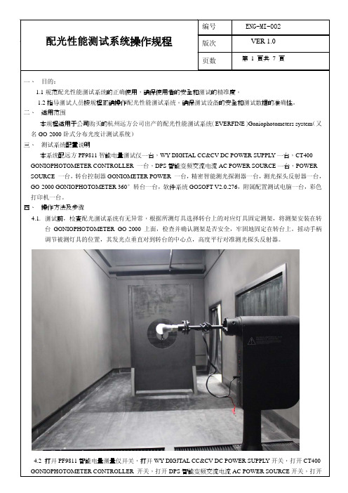
4.4打开电脑和打印机,双击电脑上“GO SOFT V2.0276"测试软件图标进入远方配光性能测试
4.5按电脑键盘上“F3"按钮,系统进入自动测试。
4.6在测试栏画面上出现测试信息对话框。
4.8点击“开始”按钮,再点击“确认”进行光分布测试。
约10分钟左右。
4.9在观察窗口观察转台360°转动,约10分钟左右设备自动完成测试后,显示测试完成画面。
4.11点击“文件”---“打印”---选打印机为“Adobe PDF”---“确定”将测试数据转换成PDF
4.12预览文件确认OK后,点击“打印”将测试数据报告打印出来(备注:一般状态下,一份测试报告有
页,如连续2次测试有22-24页,请注意删除重复测试的部分,以免浪费打印纸张。
4.13测试完毕后退出系统,点击“文件”菜单---点击“退出”
位,约3-5分钟后转台完成自动复位后会自动关闭系统。
安捷伦1200标准操作规程
Agilent 1200液相色谱仪操作规程设备组成:G1311A(四元泵)、G1329A(标准型自动进样器)、G1316A(柱温箱)、G1314B(VWD检测器)、G1315D(DAD检测器)。
基本操作步骤:(一)、开机:1、打开计算机,进入Windows XP画面。
(IP 地址由Bootp Service 程序写入)2、打开1200 LC 各模块电源。
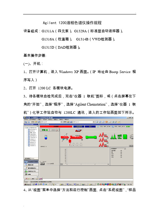
3、待各模块自检完成后,双击“仪器1 联机”图标,或(点击屏幕左下角的“开始”,选择“程序”,选择“Agilent Chemstation”,选择“仪器1 联机”)化学工作站自动与1200LC通讯,进入的工作站画面如下所示。
4、从“视图”菜单中选择“方法和运行控制”画面, 点击“系统视图”,“样品视图”,使其命令前有“√”标志,来调用所需的界面。
5、把流动相放入溶剂瓶中。
6、手动旋开冲洗阀。
7、点击“泵”图标,点击“设置泵”选项,进入泵编辑画面。
8、设流速:3-5ml/min,点击“确定”。
9、点击“泵” 图标,点击“控制”选项,选中“启动”,点击“确定” ,则系统开始冲洗,直到管线内(由溶剂瓶到泵入口)无气泡为止,切换通道继续冲洗,直到所有要用通道无气泡为止。
若使用缓冲盐,要加入泵头冲洗(seal-wash),点击“泵” 图标,点击“控制”选项,选择“用于泵密封垫清洗的泵”,开启清洗泵前要配制90%水+10%异丙醇,溶剂不能干涸。
10、点击“泵” 图标,点击“控制”选项,选中“关闭”,点击“确定”关泵,手动旋紧冲洗阀。
11、点击“泵”图标,点击“设置泵选项”,设流速:1.0ml/min。
12、点击泵下面的瓶图标,选择“溶剂瓶添充量”如下图所示(以四元泵为例),输入溶剂的实际体积和瓶体积。
也可输入停泵的体积,点击“确定”。
(二)数据采集方法编辑:1、开始编辑完整方法:从“方法”菜单中选择“编辑完整方法” 项,如下图所示选中除“数据分析”外的三项,点击“确定”,进入下一画面。
Agilent-1200型高效液相色谱仪操作说明-2ppt.

Agilent-1200型高效液相色谱仪操作说明第二章
Agilent-1200型高效液相色谱仪操作说明
4.2.3 进样序列的保存
在命令栏“Sequence”下,单击“Save Sequence”或单击快捷操作的 “Save Current Sequence”图标(左边一软盘,右边三个小瓶);在 path下选择保存路径,在此路径下选择subdiectory输入新文件名,单击 “OK”,即完成。
8.5.1 流动相使用前请必须脱气、过滤。
8.5.2 使用缓冲盐时,要加在线Seal-wash选项。
*
Agilent-1200型高效液相色谱仪操作说明
8.5.3 关机前,用 100%的乙腈冲洗系统20分钟,然后关泵,(适于反 相色谱柱,正相色谱柱用适当的溶剂冲洗)。 8.5.4 及时更换Purge Valve内的过滤芯。(当打开Purge Valve时,压 力高于10bar,表明过滤芯已堵)。 8.5.5 使用合适的密封圈。 8.6 使用梯度比例时要注意事项:
8.6.2 当使用缓冲盐溶液和有机溶剂时,推荐将缓冲盐通道接在A通道上, 有机溶剂通道直接接在A通道的上方D通道上;定期用水冲洗所有的通道, 以除去阀口上可能出现的盐沉淀。
*
Agilent-1200型高效液相色谱仪操作说明
8.7 在线真空脱气机使用注意事项: 8.7.1 第一次使用,要用随仪器附带的注射器抽满脱气机腔体;更换不 同类型的溶剂时,要先抽空,再抽满。 8.7.2 不用的通道要充满溶剂或密闭起来。 8.8 更换色谱柱时要注意事项:
*
Agilent-1200型高效液相色谱仪操作说明
仪器的流动相管路连接非常重要,一般Agilent 1200LC 在第 一次安装时,均有受过专业培训的安装工程师负责安装,各 种接头会处理的非常完美。客户只需在更换色谱柱时注意接 头处理就可以了,一般柱子入口接头为不锈钢卡套接头,柱 子出口为不锈钢卡套接头或PEEK管线手拧街头,当完成第 一次安装后,不锈钢卡套已固定死,当接不同的柱子时,要 注意柱子接头处的形状和长度,否则会产生一个非常大的死 体积。
积分球光谱测量仪操使用说明书
页数第 1 頁共7 頁1、目的:1.1规范积分球测量系统的测试使用,确保使用者的安全和测试的精度。
1.2指导测试人员按规程正确操作积分球测试系统。
确保测试设备的安全和测试数据的准确性。
2、适用范围本规程适用于公司购买的杭州远方公司出产的0.3米和2米的积分球测试系统和远方(EVERFINE)HAAS-1200高精度快速光谱辐射计测试与分析系统。
3、测试系统配置说明本系统配远方0.3米积分球一套,2米积分球一套,YF1000 LAMP COMPLETE ANAL YSIS SYSTEM 系统和配套的PF9811智能电量测试仪一台,WY DIGJTAL CC&CV DC POWER SUPPL Y一台,HAAS-1200精密快速光谱辐射计一台,ACCURATE ARRAY SPECTROMETER 一台,DPS智能变频交流电流AC POWER SOURCE一台,软件系统HAAS SUITE –V2,00,410,附属配置测试电脑一台,彩色打印机一台。
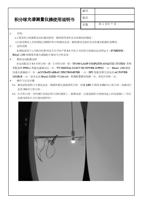
4、操作方法及步骤4.1.测试前检查积分卡测试系统,根据所测光源选择积分球,如测LED灯珠用0.3M的小积分球,如测试灯具用2M的大积分球。
4.2.打开积分球,将所测灯具装在积分球的测架上,接通电源,注意选接积分球接线盒上的电源插口(有灯具接线图和日光灯接线图两类)页数第 2 頁共7 頁4.3.打开PF9811智能电量测量仪开关,打开HAAS-1200光谱辐射计开关。
打开DPS交流电源开关,按下,检查DPS输出电压是否写被测灯具标称电压一致,不一致时奖DPS设定成与被测灯具标称电压和频率一致(例如:标称是220V 50Hz),OK, 然后按下DPS的输出开关,检查被测灯是否点亮,点亮OK.4.4.打开电脑和打印机,双击电脑上“大积分球HAAS S uite”测试软件图标进入光谙测试分析状态。
4.5.点击单次测试按钮“◀”,系统进入自动测试。
页数第 3 頁共7 頁4.6.测试结果出现在测试栏,双击测信息,出现测试信息对话框4.7.在测试信息对话框中输入产品型号,编号,测试人员姓名,点击确定。
满asa科技Whelen lightbar照明系统用户手册说明书
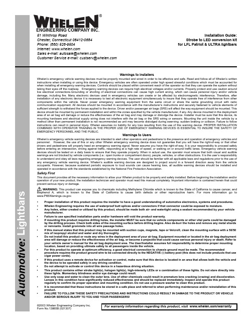
©2003 Whelen Engineering Company Inc.Form No.13865B (021307)A u t o m o t i v e : For warranty information regarding this product, visit /warranty•Proper installation of this product requires the installer to have a good understanding of automotive electronics, systems and procedures.•Whelen Engineering requires the use of waterproof butt splices and/or connectors if that connector could be exposed to moisture.•Any holes, either created or utilized by this product, should be made both air- and watertight using a sealant recommended by your vehicle manufacturer.•Failure to use specified installation parts and/or hardware will void the product warranty.•If mounting this product requires drilling holes, the installer MUST be sure that no vehicle components or other vital parts could be damaged by the drilling process. Check both sides of the mounting surface before drilling begins. Also de-burr the holes and remove any metal shards or remnants. Install grommets into all wire passage holes.•If this manual states that this product may be mounted with suction cups, magnets, tape or Velcro®, clean the mounting surface with a 50/50 mix of isopropyl alcohol and water and dry thoroughly.•Do not install this product or route any wires in the deployment area of your air bag. Equipment mounted or located in the air bag deployment area will damage or reduce the effectiveness of the air bag, or become a projectile that could cause serious personal injury or death. Refer to your vehicle owner’s manual for the air bag deployment area. The User/Installer assumes full responsibility to determine proper mounting location, based on providing ultimate safety to all passengers inside the vehicle.•For this product to operate at optimum efficiency, a good electrical connection to chassis ground must be made. The recommendedprocedure requires the product ground wire to be connected directly to the NEGATIVE (-) battery post (this does not include products that use cigar power cords).•If this product uses a remote device for activation or control, make sure that this device is located in an area that allows both the vehicle and the device to be operated safely in any driving condition.•Do not attempt to activate or control this device in a hazardous driving situation.•This product contains either strobe light(s), halogen light(s), high-intensity LEDs or a combination of these lights. Do not stare directly into these lights. Momentary blindness and/or eye damage could result.•Use only soap and water to clean the outer lens. Use of other chemicals could result in premature lens cracking (crazing) and discoloration. Lenses in this condition have significantly reduced effectiveness and should be replaced immediately. Inspect and operate this product regularly to confirm its proper operation and mounting condition. Do not use a pressure washer to clean this product.•It is recommended that these instructions be stored in a safe place and referred to when performing maintenance and/or reinstallation of this product.•FAILURE TO FOLLOW THESE SAFETY PRECAUTIONS AND INSTRUCTIONS COULD RESULT IN DAMAGE TO THE PRODUCT OR VEHICLE AND/OR SERIOUS INJURY TO YOU AND YOUR PASSENGERS!Warnings to InstallersWhelen’s emergency vehicle warning devices must be properly mounted and wired in order to be effective and safe. Read and follow all of Whelen’s written instructions when installing or using this device. Emergency vehicles are often operated under high speed stressful conditions which must be accounted for when installing all emergency warning devices. Controls should be placed within convenient reach of the operator so that they can operate the system without taking their eyes off the roadway. Emergency warning devices can require high electrical voltages and/or currents. Properly protect and use caution around live electrical connections.Grounding or shorting of electrical connections can cause high current arcing, which can cause personal injury and/or vehicle damage, including fire. Many electronic devices used in emergency vehicles can create or be affected by electromagnetic interference. Therefore, after installation of any electronic device it is necessary to test all electronic equipment simultaneously to insure that they operate free of interference from other components within the vehicle. Never power emergency warning equipment from the same circuit or share the same grounding circuit with radio communication equipment. All devices should be mounted in accordance with the manufacturer’s instructions and securely fastened to vehicle elements of sufficient strength to withstand the forces applied to the device. Driver and/or passenger air bags (SRS) will affect the way equipment should be mounted. This device should be mounted by permanent installation and within the zones specified by the vehicle manufacturer, if any. Any device mounted in the deployment area of an air bag will damage or reduce the effectiveness of the air bag and may damage or dislodge the device. Installer must be sure that this device, its mounting hardware and electrical supply wiring does not interfere with the air bag or the SRS wiring or sensors. Mounting the unit inside the vehicle by a method other than permanent installation is not recommended as unit may become dislodged during swerving; sudden braking or collision. Failure to follow instructions can result in personal injury. Whelen assumes no liability for any loss resulting from the use of this warning device. PROPER INSTALLATION COMBINED WITH OPERATOR TRAINING IN THE PROPER USE OF EMERGENCY WARNING DEVICES IS ESSENTIAL TO INSURE THE SAFETY OF EMERGENCY PERSONNEL AND THE PUBLIC.Warnings to UsersWhelen’s emergency vehicle warning devices are intended to alert other operators and pedestrians to the presence and operation of emergency vehicles and personnel. However, the use of this or any other Whelen emergency warning device does not guarantee that you will have the right-of-way or that other drivers and pedestrians will properly heed an emergency warning signal. Never assume you have the right-of-way. It is your responsibility to proceed safely before entering an intersection, driving against traffic, responding at a high rate of speed, or walking on or around traffic lanes. Emergency vehicle warning devices should be tested on a daily basis to ensure that they operate properly. When in actual use, the operator must ensure that both visual and audible warnings are not blocked by vehicle components (i.e.: open trunks or compartment doors), people, vehicles, or other obstructions. It is the user’s responsibility to understand and obey all laws regarding emergency warning devices. The user should be familiar with all applicable laws and regulations prior to the use of any emergency vehicle warning device. Whelen’s audible warning devices are designed to project sound in a forward direction away from the vehicle occupants. However, because sustained periodic exposure to loud sounds can cause hearing loss, all audible warning devices should be installed and operated in accordance with the standards established by the National Fire Protection Association.Safety FirstThis document provides all the necessary information to allow your Whelen product to be properly and safely installed. Before beginning the installation and/or operation of your new product, the installation technician and operator must read this manual completely. Important information is contained herein that could prevent serious injury or damage.WARNING: This product can expose you to chemicals including Methylene Chloride which is known to the State of California to cause cancer, and Bisphenol A, which is known to the State of California to cause birth defects or other reproductive harm. For more information go to .Installation Guide:Strobe to LED conversion kit for LFL Patriot & ULTRA lightbars51 Winthrop RoadChester, Connecticut 06412-0684Phone: (860) 526-9504Internet: Salese-mail:*******************CustomerServicee-mail:*******************®ENGINEERING COMPANY INC.LFL Patriot: 1.Remove the endcaps (T25 torx head) and unplug the alley lights if present. Also unplug and remove the corner lightheads. Remove the 4 top extrusion torx screws (T20 torx head) and remove the top extrusion. (Slide the lenses out and place them on your work area in the order you removed them for easy re-installation.)2.Unplug and remove the strobe power supply you wish to replace.3.Plug the ballast interconnect harness into the ballast you are installing and install the ballast with the connectors on the ballast facing inward (the opposite way the power supply connectors faced). You may have to cut one or more ty-wraps from the main harness to allow you to turn the ballast around.Note:You must also turn the other strobe power supply around so itsconnectors face inward to make room for the extra wiring. 4.Plug the other end of the ballast’s interconnect harness into the lightbar ports you removed the power supply harness from (The connectors will match the ones you removed).WARNING!Use ty-wraps to hold the harness in its new position and make sureall wires are positioned out of the way of other components, so they will not get crushed during reassembly. 5.Unplug and remove the lightheads you are replacing. Plug the LED retrofit adapters onto the LED lightheads you are installing then install the LED lightheads in the spots you removed the strobe lightheads from. Reassemble and test the lightbar.ULTRA: 1.Remove the endcaps (T25 torx head) and unplug the alley lights if present.2.Slide as many lenses and lightheads out of the lightbar as is necessary to access the power supply you wish to replace. Place them on your work area in the order that you removed them for easy re-installation.3.Unplug and remove the strobe power supply you wish to replace.4.Plug the ballast interconnect harness into the ballast you are installing and install the ballast. Unlike the LFL, the ballast for the ULTRA will install in the same position as the power supply you removed (with connectors facing the outside of the lightbar).5.Plug the other end of the ballast’s interconnect harness into the lightbar ports you removed the power supply harness from (The connectors will match the ones you removed).6.Unplug and remove the lightheads you are replacing. Plug the LED retrofit adapters onto the LED lightheads you are installing then install the LED lightheads in the spots you removed the strobe lightheads from.Reassemble and test the lightbar.WARNING!Position all wires out of theway of other components, so they will not get crushed or pinched during reassembly.WARNING!The strobe power supply is a high voltage device. Do not remove the strobe tubes or dismantle the strobe lightheads in the system while the unit is in operation. Wait 10 minutes after turning off power Before starting any work or trouble shooting on the system.Be sure power is off and the main fuse is removed. The diagrams above show which strobe power supplies control which strobe lightheads to identify which power supply controls the lightheads you wish to change.IMPORTANT: The LED ballast for both the ULTRA and PATRIOT follows the basic function of the existing strobe power supplies. Some functions however, will not be possible. For proper performance, the ballast should be used in ALTERNATING MODE ONLY. This may require a change to your SC control head. SC modes such as SIMULTANEOUS, IN-OUT and RANDOM will cause errors and are not recommended. These ballasts are unique and should be treated as such. When changing patterns, the ballast needs to first detect the active pattern coming from the I.O. card and then sync up with it. This may take one or two cycles and some minor flash glitches may be seen in the pattern during this process. ACTION SCAN may display some minor flash glitches since the patterns change often.。
v1200分光光度计的使用方法

v1200分光光度计的使用方法
以下是v1200分光光度计的使用步骤:
1.首先,确保仪器的电源线正确连接,并将仪器连接到电源插座。
2.接下来,打开仪器的电源开关,待仪器的指示灯亮起表示仪器已正常开机。
3.然后,打开仪器的光栅护罩,同时将样品槽打开。
注意,使用时应尽量避免直接接触光栅和样品槽,以防止污染或损坏。
4.将待测样品或标准溶液放入样品槽中,并确保样品槽完全关闭。
5.选择合适的波长,可通过仪器上的波长选择旋钮进行调节。
在选择波长时,应根据待测样品的特性和需要测量的光谱范围进行选择。
6.调节参考光电流至适宜水平。
参考光电流是仪器用于校正背景噪音和光源变化的基准电流。
通常可以通过调节仪器上的参考光电流旋钮来调节。
7.根据需要选择测量方式,可以选择吸光度、纵向光强度或横向光强度测量。
可以通过仪器上的测量方式选择旋钮来选择测量方式。
8.开始测量前,为了提高准确性,建议使用空白样品来校正仪器。
9.最后,按下测量按钮开始测量,并等待一段时间,直到仪器测量完成。
测量结果将在仪器上显示或输出。
10.完成测量后,关闭仪器的电源开关,并关闭光栅护罩和样品槽。
请注意,在操作过程中要特别注意避免光源伤害眼睛,避免长时间直视光源。
此外,在使用前应仔细阅读仪器的操作手册,以确保正确的操作和仪器的正常使用。
AQ1200简易操作手册
• 本手册的内容将随仪器性能及功能的提升而改变,恕不提前通知。另外,本手册中的图片可能与仪器实际显示图片有差异。 • 我们努力将本手册的内容做到完善。如果您有任何疑问或发现任何错误,请与 YOKOGAWA 或 YOKOGAWA 的经销商联系。 • 严禁在未经横河电机株式会社允许的情况下,拷贝、转载本手册的全部或部分内容。
手提带 B8070CX
肩带 B8070CY1
铁氧体磁芯 A1190MN
操作手册
• 简易操作手册 ( 本手册 )
• 其它手册
• 操作手册 B8078VB (CD-ROM)2
1 如果后缀代码为 /SB,则包括。 2 可以单独购买印刷版操作手册 IM AQ1200-01EN 和 IM
AQ1200-17EN。需要时,请与 YOKOGAWA 经销商联系。
商标
• Microsoft、Windows、Windows XP 和 Windows Vista 是微软公司在美国和 / 或其它国家的商标或注册商标。 • Adobe、Acrobat 和 PostScript 是 Adobe Systems Incorporated 的商标。 • 本手册中出现的各公司的注册商标或商标,将不使用 TM 和 ® 标记。 • 本手册中出现的其它公司名和产品名均属于各自公司的商标或注册商标。
后缀代码为 -USC 或 -ASC 时提供
FC 通用适配器 SC 连接器的适配器 FC 连接器的适配器 金属环状适配器 (1.25f)
SU2005A-FCC 735480-SCC 735480-FCC 735481-LMC
后缀代码为 -UFC 时提供
功率计测量 (OPM) 端口用 这些附件可与带损耗测量选件 (/SLT 或 /HLT) 的机型一起使用
- 1、下载文档前请自行甄别文档内容的完整性,平台不提供额外的编辑、内容补充、找答案等附加服务。
- 2、"仅部分预览"的文档,不可在线预览部分如存在完整性等问题,可反馈申请退款(可完整预览的文档不适用该条件!)。
- 3、如文档侵犯您的权益,请联系客服反馈,我们会尽快为您处理(人工客服工作时间:9:00-18:30)。
z 没有本公司书面许可,任何抄袭或改编本手册内容均为严重侵权。 z 对于手册内容如有不同理解,以本公司技术部门解释为准。
开箱检查
用户第一次打开仪器包装箱时,请对照装箱清单检查仪器和配件,若发现仪 器或配件错误、配件不齐或是不正常,请与销售商或生产商联系。
本用户手册及包括的任何资料,其版权归远方公司所有,受中华人民共和国 著作权法或国际相关法律保护。未经本公司书面许可,任何单位或个人不得以任 何方式或形式对本手册部分或全部内容进行复制、修改、传播、摘录、备Байду номын сангаас、翻 译成其他语言。否则将构成对本公司著作权的侵犯,侵权者将承担相关的法律后 果以及本公司的全部损失。本用户手册已增加了对应产品的唯一性产品编号,任 何上述的侵权行为都可由此追溯到责任用户。
HAAS-1200 用户手册
前言
带格式的: 下划线
感谢购置远方 HAAS-1200 精密快速光谱辐射计。本用户手册包含仪器功能、 操作过程以及安全规定等,为了确保正确使用本仪器,在操作仪器前请仔细阅读 手册。请妥善保存手册,以便碰到问题时能快速查阅。
注意:
z 本公司奉行不断完善改进产品的宗旨,因此手册内容有可能改变,恕不 另行通知。
If EVERFINE has signed a written agreement with user and the contents in the agreement are in conflict with above terms, the contents in the written agreement have preferential force effect.
常现象,请与远方公司技术服务部联系。建议用户专人负责操作,并建 立操作规范。
杭州远方光电信息股份有限公司版权所有,未经许可不得复制和传播。3
HAAS-1200 用户手册
目录
前 言 .........................................................................................................................1 版权申明 .....................................................................................................................2 注意事项 .....................................................................................................................3 第一章 概 述............................................................................................................86 第二章 主要性能与技术指标 ..................................................................................97 第三章 仪器面板及安装 ........................................................................................ 119
1. 请勿用手触摸光度探测器的受光面,若探测器的受光面有污物,请用洗 耳球或专用的擦镜纸进行擦拭。
2. 仪器放置应安装可靠,周围无强烈的振动。 3. 长时间测量强光源,会影响仪器感光性能。 4. 请保持工作环境清洁,工作台稳定; 5. 电源必须是单相三线制的,必须有良好的接地。若仍出现通讯中断等不正
杭州远方光电信息股份有限公司版权所有,未经许可不得复制和传播。1
HAAS-1200 用户手册
版权申明
The copyright of this manual and the related information belongs to EVERFINE, and it is protected by the copyright law of People's Republic of China and other relevant international treaties. Copying, modifying, spreading, excerpting, backing up or translating the whole or part contents of this manual by any company or personnel without the written permission of EVERFINE is prohibited. Otherwise it will be treated as infringement and the infringer will assume law responsibility and all loss of EVERFINE. Any infringement related above can be traced back to the responsible user by the unique product number printed in the manual.
Zone, Hangzhou(310053), China Tel :86-571-86698333 Fax :86-571-86696433 E-mail:Sales@ 销售专箱
Service@ 服务专箱 http://
杭州远方光电信息股份有限公司版权所有,未经许可不得复制和传播
HAAS-1200
精密快速光谱辐射计 (工业级) 用户手册
Ver 1.12
HAAS-1200 ACCURATE ARRAY SPECTRORADIOMETER
USER’S MANUAL
Ver 1.12
杭州远方光电信息股份有限公司 EVERFINE Corporation (Stock Code: 300306). 地址:杭州市滨江区滨康路 669 号 1 号楼(310053) ADD:Bldg.1, #669 Binkang Rd., Binjiang Hi-Tech
如果本公司与用户签有其他的书面协议,且协议中涉及的本文档所含材料的 担保条款与上述条款有冲突,则该书面协议中的担保条款具有优先法律效力。
带格式的: 下划线
2 杭州远方光电信息股份有限公司版权所有,未经许可不得复制和传播。
HAAS-1200 用户手册
注意事项
带格式的: 下划线
使用本仪器前,确保测控软件编号与仪器编号一致,否则会严重影响测量精 度。并且在使用过程中,请注意以下事项:
3.1 仪器组成 ...................................................................................................... 119 3.1.1 仪器前面板.................................................................................................119 3.1.2 仪器后面板...............................................................................................1210 3.2 仪器安装 .................................................................................................... 1311 3.2.1 电源连接...................................................................................................1311 3.2.2 通讯线连接...............................................................................................1311 3.2.3 光纤连接...................................................................................................1311 3.2.4 应用软件安装...........................................................................................1412 第四章 操作指南..................................................................................................1613 4.1 软件概述 ....................................................................................................1613 4.1.1 软件启动 ...................................................................................................1613 4.1.2 主界面介绍 ...............................................................................................1714 4.2 测试过程 ....................................................................................................2017 4.2.1 系统设置 ...................................................................................................2017 4.2.2 光谱测试 ...................................................................................................2420 4.3 仪器定标......................................................................................................2622 4.3.1 光谱定标 ...................................................................................................2622 4.3.2 光度定标 ...................................................................................................2723 4.3.3 荧光粉相对亮度定标................................................................................2824 4.4 波长校正校验 ............................................................................................2924 4.5 其它功能 ....................................................................................................3025 4.5.1 分级与分类 ...............................................................................................3025