外文翻译--液压系统和气压系统
液压与气压传动课件(英文版)

-----------------------------------------------------------------------------------
1.3 Viscosity
1.3.1 cohesion force and adhesion force
There are cohesion forces among fluid particles, while there are adhesion forces among fluid particles and solid wall.
Adhesion forces are usually greater than cohesion force except mercury. 1.3.2 dynamic viscosity
Consider two parallel plates, placed a small distance Y apart, the space between the plates being filled with the fluid.
Hydraulics and Pneumatics
Transmission
FLUID MECHANICS WITH HYDRAULICS
1 Fluid Properties 2 Mechanics of fluids at rest 3 Mechanics of fluids in motion 4 Energy loss of fluids in motion 5 Flow of fluids in clearances and orifices 6 Hydraulically sticking 7 Hydraulically shocking 8 Cavitation
液压系统外文翻译解析
(外文翻译——中文)液压系统液压传动和气压传动称为流体传动,是根据17世纪帕斯卡提出的液体静压力传动原理而发展起来的一门新兴技术,1795年英国约瑟夫•布拉曼(Joseph Braman,1749-1814),在伦敦用水作为工作介质,以水压机的形式将其应用于工业上,诞生了世界上第一台水压机。
1905年将工作介质水改为油,又进一步得到改善。
第一次世界大战(1914-1918)后液压传动广泛应用,特别是1920年以后,发展更为迅速。
液压元件大约在 19 世纪末 20 世纪初的20年间,才开始进入正规的工业生产阶段。
1925 年维克斯(F.Vikers)发明了压力平衡式叶片泵,为近代液压元件工业或液压传动的逐步建立奠定了基础。
20 世纪初康斯坦丁•尼斯克(G•Constantimsco)对能量波动传递所进行的理论及实际研究;1910年对液力传动(液力联轴节、液力变矩器等)方面的贡献,使这两方面领域得到了发展。
第二次世界大战(1941-1945)期间,在美国机床中有30%应用了液压传动。
应该指出,日本液压传动的发展较欧美等国家晚了近 20 多年。
在 1955 年前后 , 日本迅速发展液压传动,1956 年成立了“液压工业会”。
近20~30 年间,日本液压传动发展之快,居世界领先地位。
液压传动有许多突出的优点,因此它的应用非常广泛,如一般工业用的塑料加工机械、压力机械、机床等;行走机械中的工程机械、建筑机械、农业机械、汽车等;钢铁工业用的冶金机械、提升装置、轧辊调整装置等;土木水利工程用的防洪闸门及堤坝装置、河床升降装置、桥梁操纵机构等;发电厂涡轮机调速装置、核发电厂等等;船舶用的甲板起重机械(绞车)、船头门、舱壁阀、船尾推进器等;特殊技术用的巨型天线控制装置、测量浮标、升降旋转舞台等;军事工业用的火炮操纵装置、船舶减摇装置、飞行器仿真、飞机起落架的收放装置和方向舵控制装置等。
一个完整的液压系统由五个部分组成,即动力元件、执行元件、控制元件、辅助元件和液压油。
液压英文文献及翻译

液压英文文献及翻译液压系统1.绪论液压站称液压泵站,是独立的液压装置。
它是按逐级要求供油。
并控制液压油流方向、压力和流量,适用在主机与液压装置可分离的各种液压机械上面。
用户在购后只要将液压站与主机上执行机构(油缸或油马达)用不同的油管相连,液压机械即实现各种规定的动作与工作循环。
液压站是由集成块、泵装置或阀组合、电气盒、油箱电气盒组合而成。
各个部件功能为:泵装置——上装有电机和油泵,其是液压站的动力源,能将机械能转化为液压油压力能。
阀组合--其板式阀装在立板上,板后管连接,与集成块的功能相同。
油集成块--是由液压阀及通道体组装而成。
其对液压油实行压力、方向和流量调节。
箱--是板焊的半封闭容器,上面还装有滤油网、空气滤清器等,是用来储油与油的冷却及过滤。
电气盒--分两种型式:一种是设置外接引线的端子板;一种是配置了全套控制电器。
液压站工作原理:电机带动油泵转动,然后泵从油箱中吸油并供油,将机械能转化为液压站压力能,液压油通过集成块(或阀组合)实现方向、压力、流量调节后经过外接管路并至液压机械里的油缸或油马达中,从而控制液动机方向变换、力量的大小及速度的快慢,来推动各种液压机械做功。
(1)液压的发展历程在我国液压(含液力,下同)、气动和密封件工业的发展历程,大致可分成三个阶段,即:在20世纪50年代初到60年代初是起步阶段;60-70年代为专业化生产体系的成长阶段;80-90年代为快速发展阶段。
在其中,液压工业始于50年代初从机床行业生产的仿苏的磨床、拉床、仿形车床等液压传动来起步,液压元件由机床厂里的液压车间生产,自产自用。
在进入60年代后,液压技术应用从机床逐渐推广到农业机械与工程机械等领域,原来附属于主机厂里的液压车间有些独立出来,成为液压件的专业生产厂。
在60年代末、70年代初,随着生产机械化的不断发展,特别是在为第二汽车制造厂等提供了高效、自动化设备的带动下,液压元件制造业出现了不断迅速发展的局面,一批中小企业也开始成为液压件专业制造厂。
液压系统外文翻译

Hydraulic SystemHydraulic presser drive and air pressure drive hydraulic fluid as the transmission is made according to the 17th century, Pascal's principle of hydrostatic pressure to drive the development of an emerging technology, the United Kingdom in 1795 •Braman Joseph (Joseph Braman ,1749-1814), in London water as a medium to form hydraulic press used in industry, the birth of the world's first hydraulic press. Media work in 1905 will be replaced by oil-water and further improved.After the World War I (1914-1918) ,because of the extensive application of hydraulic transmission, espec- ially after 1920, more rapid development. Hydraulic components in the late 19th century about the early 20th century, 20 years, only started to enter the formal phase of industrial production. 1925 Vickers (F. Vikers) the invention of the pressure balanced vane pump, hydraulic components for the modern industrial or hydraulic transmission of the gradual establishment of the foundation. The early 20th century G • Constan timscofluct- uations of the energy carried out by passing theoretical and practical research; in 1910 on the hydraulic trans- mission (hydraulic coupling, hydraulic torque converter, etc.) contributions, so that these two areas of develo- pment.The Second World War (1941-1945) period, in the United States 30% of machine tool applications in the hydraulic transmission. It should be noted that the development of hydraulic transmission in Japan than Europe and the United States and other countries for nearly 20 years later. Before and after in 1955, the rapid development of Japan's hydraulic drive, set up in 1956, "Hydraulic Industry." Nearly 20 to 30 years, the development of Japan's fast hydraulic transmission, a world leader.Hydraulic transmission There are many outstanding advantages, it is widely used, such as general industr- ial use of plastics processing machinery, the pressure of machinery, machine tools, etc.; operating machinery engineering machinery, construction machinery, agricultural machinery, automobiles, etc.; iron and steel indu- stry metallurgical machinery, lifting equipment, such as roller adjustment device; civil water projects with flo- od control and dam gate devices, bed lifts installations, bridges and other manipulation of institutions; speed turbine powerplant installations, nuclear power plants, etc.; ship from the deck heavy machinery (winch), the bow doors, bulkhead valve, stern thruster, etc.; special antenna technology giant with control devices, measu- rement buoys, movements such as rotating stage; military-industrial control devices used in artillery, ship anti- rolling devices, aircraft simulation, aircraft retractable landing gear and rudder control devices and other devi- ces.A complete hydraulic system consists of five parts, namely, power components, the implementation of co- mponents, control components, auxiliary components and hydraulic oil.The role of dynamic components of the original motive fluid into mechanical energy to the pressure that the hydraulic system of pumps, it is to power the entire hydraulic system. The structure of the form of hydra- ulic pump gears are generally pump, vane pump and piston pump.Implementation of components (such as hydraulic cylinders and hydraulic motors) which is the pressure of the liquid can be converted to mechanical energy to drive the load for a straight line reciprocating movement or rotational movement.Control components (that is, the various hydraulic valves) in the hydraulic system to control and regulate the pressure of liquid, flow rate and direction. According to the different control functions, hydraulic pressure control valve can be divided into valves, flow control valves and directional control valve. Pressure control valves are divided into benefits flow valve (safety valve), pressure relief valve, sequence valve, pressure relays, etc.; flow control valves including throttle, adjusting the valves, flow diversion valve sets, etc.; directional control valve includes a one-way valve , one-way fluid control valve, shuttle valve, valve and so on. Under the control of different ways, can be divided into the hydraulic valve control switch valve, control valve and set the value of the ratio control valve.Auxiliary components, including fuel tanks, oil filters, tubing and pipe joints, seals, pressure gauge, oil level, such as oil dollars.Hydraulic oil in the hydraulic system is the work of the energy transfer medium, there are a variety of mineral oil, emulsion oil hydraulic molding Hop categories.The role of the hydraulic system is to help humanity work. Mainly by the implementation of components to rotate or pressure into a reciprocating motion.Hydraulic system and hydraulic power control signal is composed of two parts, the signal control of some parts of the hydraulic power used to drive the control valve movement.Part of the hydraulic power means that the circuit diagram used to show the different functions of the interrelationship between components. Containing the source of hydraulic pump, hydraulic motor and auxiliary components; hydraulic control part contains a variety of control valves, used to control the flow of oil, pressure and direction; operative or hydraulic cylinder with hydraulic motors, according to the actual requirements of their choice.In the analysis and design of the actual task, the general block diagram shows the actual operation of equi - pment. Hollow arrow indicates the signal flow, while the solid arrows that energy flow.Basic hydraulic circuit of the action sequence - Control components (twofour-way valve) and the spring to reset for the implementation of components (double-acting hydraulic cylinder), as well as the extending and retracting the relief valve opened and closed . For the implementation of components and control components, presentations are based on the corresponding circuit diagram symbols, it also introduced ready made circuit diagram symbols.Working principle of the system, you can turn on all circuits to code. If the first implementation of components numbered 0, the control components associated with the identifier is 1. Out with the implementation of components corresponding to the identifier for the even components, then retracting and implementation of components corresponding to the identifier for the odd components. Hydraulic circuit carried out not only to deal with numbers, but also to deal with the actual device ID, in order to detect system failures.DIN ISO1219-2 standard definition of the number of component composition, which includes the following four parts: device ID, circuit ID, component ID and component ID. The entire system if only one device, device number may be omitted.Practice, another way is to code all of the hydraulic system components for numbers at this time, components and component code should be consistent with the list of numbers. This method is particularly applicable to complex hydraulic control system, each control loop are the corresponding number with the system With mechanical transmission, electrical transmission compared to the hydraulic drive has the following advantages:1, a variety of hydraulic components, can easily and flexibly to layout.2, light weight, small size, small inertia, fast response.3, to facilitate manipulation of control, enabling a wide range of stepless speed regulation (speed range of 2000:1).4, to achieve overload protection automatically.5, the general use of mineral oil as a working medium, the relative motion can be self-lubricating surface, long service life;6, it is easy to achieve linear motion /7, it is easy to achieve the automation of machines, when the joint control of the use of electro-hydraulic, not only can achieve a higher degree of process automation, and remote control can be achieved.The shortcomings of the hydraulic system:1, as a result of the resistance to fluid flow and leakage of the larger, so less efficient. If not handled properly, leakage is not only contaminated sites, but also may cause fire and explosion.2, vulnerable performance as a result of the impact of temperature change, it would be inappropriate in the high or low temperature conditions.3, the manufacture of precision hydraulic components require a higher, more expensive and hence the price.4, due to the leakage of liquid medium and the compressibility and can not be strictly the transmission ratio.5, hydraulic transmission is not easy to find out the reasons for failure; the use and maintenance requirements for a higher level of technology.In the hydraulic system and its system, the sealing device to prevent leakage of the work of media within and outside the dust and the intrusion of foreign bodies. Seals played the role of components, namely seals. Medium will result in leakage of waste, pollution and environmental machinery and even give rise to malfunctioning machinery and equipment for personal accident. Leakage within the hydraulic system will cause a sharp drop in volumetric efficiency, amounting to less than the required pressure, can not even work. Micro-invasive system of dust particles, can cause or exacerbate friction hydraulic component wear, and further lead to leakage.Therefore, seals and sealing device is an important hydraulic equipment components. The reliability of its work and life, is a measure of the hydraulic system an important indicator of good or bad. In addition to the closed space, are the use of seals, so that two adjacent coupling surface of the gap between the need to control the liquid can be sealed following the smallest gap. In the contact seal, pressed into self-seal-style and self-styled self-tight seal (ie, sealed lips) two.The three hydraulic system diseases1, as a result of heat transmission medium (hydraulic oil) in the flowvelocity in various parts of the existence of different, resulting in theexistenceof a liquid within the internal friction of liquids and pipelines at the sam- etime there is friction between the inner wall, which are a result of hydraulic the reasons for the oil tempera- ture. Temperature will lead to increased internaland external leakage, reducing its mechanical efficiency. At the same time as aresult of high temperature, hydraulic oil expansion will occur, resulting in increased com- pression, so that action can not be very good control of transmission. Solution: heat is the inherent characte -ristics of the hydraulic system, not only to minimize eradication. Use a good quality hydraulic oil, hydraulic piping arrangement should be avoided as far as possible theemergence of bend, the use of high-quality pipe and fittings, hydraulic valves,etc.2, the vibration of the vibration of the hydraulic system is also one of its malaise. As a result of hydraulic oil in the pipeline flow of high-speed impact and the control valve to open the closure of the impact of the process are the reasons for the vibration system. Strong vibration control action will cause the system to error, the system will also be some of the more sophisticated equipment error, resulting in system failures. Solutions: hydraulic pipe should be fixed to avoid sharp bends. To avoid frequent changes in flow direction, can not avoid damping measures should be doing a good job. The entire hydraulic system should have a good damping measures, while avoiding the external local oscillator on the system.3, the leakage of the hydraulic system leak into inside and outside the leakage leakage. Leakage refers to the process with the leak occurred in the system, such as hydraulic piston-cylinder on both sides of the leakage, the control valve spool and valve body, such as between the leakage. Although no internal leakage of hydra- ulic fluid loss, but due to leakage, the control of the established movements may be affected until the cause system failures. Outside means the occurrence of leakage in the system and the leakage between the external environment. Direct leakage of hydraulic oil into the environment, in addition to the system will affect the working environment, not enough pressure will cause the system to trigger a fault. Leakage into the enviro- nment of the hydraulic oil was also the danger of fire. Solution: the use of better quality seals to improve the machining accuracy of equipment.Another: the hydraulic system for the three diseases, it was summed up: "fever, with a father拉稀" (This is the summary of the northeast people). Hydraulic system for the lifts, excavators, pumping station, dynamic, crane, and so on large-scaleindustry, construction, factories, enterprises, as well as elevators, lifting platforms, Deng Axle industry and so on.Hydraulic components will be high-performance, high-quality, high reliability, the system sets the direction of development; to the low power, low noise, vibration, without leakage, as well as pollution control, water-based media applications to adapt to environmental requirements, such as the direction of development; the development of highly integrated high power density, intelligence, mechatronics and micro-light mini-hydraulic components; active use of new techniques, new materials and electronics, sensing and other high-tech.---- Hydraulic coupling to high-speed high-power and integrated development of hydraulic transmission equ- ipment, development of water hydraulic coupling medium speed and the field of automotive applications to develop hydraulic reducer, improve product reliability and working hours MTBF; hydraulic torque converter to the development of high-power products, parts and components to improve the manufacturing process tech -nology to improve reliability, promote computer-aided technology, the development of hydraulic torque con- verter and power shift transmission technology supporting the use of ; Clutch fluid viscosity should increase the quality of products, the formation of bulk to the high-power and high-speed direction.Pneumatic Industry:---- Products to small size, light weight, low power consumption, integrated portfolio of development, the implementation of the various types of components, compact structure, high positioning accuracy of the direction of development; pneumatic components and electronic technology, to the intelligent direction of development; component performance to high-speed, high-frequency, high-response, high-life, high temp- erature, high voltage direction, commonly used oil-free lubrication, application of new technology, new technology and new materials.(1) used high-pressure hydraulic components and the pressure of continuous work to reach 40Mpa, the maximum pressure to achieve instant 48Mpa;(2) diversification of regulation and control;(3) to further improve the regulation performance, increase the efficiency of the powertrain;(4) development and mechanical, hydraulic, power transmission of the composite portfolio adjustment gear;(5) development of energy saving, energy efficient system function;(6) to further reduce the noise;(7) Application of Hydraulic Cartridge Valves thread technology, compact structure, to reduce the oil spill.液压系统液压传动和气压传动称为流体传动,是根据17世纪帕斯卡提出的液体静压力传动原理而发展起来的一门新兴技术,1795年英国约瑟夫•布拉曼(Joseph Braman,1749-1814),在伦敦用水作为工作介质,以水压机的形式将其应用于工业上,诞生了世界上第一台水压机。
机械外文翻译文献翻译液压系统1
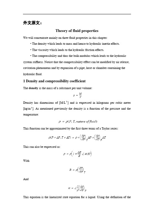
外文原文:Theory of fluid propertiesWe will concentrate mainly on three fluid properties in this chapter:• The density which leads to mass and hence to hydraulic inertia effects.• The viscosity which leads to the hydraulic friction effects.• The compressi bility and thus the bulk modulus which leads to the hydraulic system stiffness. Notice that the compressibility effect can be modified by air release, cavitation phenomena and by expansion of a pipe, hose or chamber containing the hydraulic fluid.1 Density and compressibility coefficientThe density is the mass of a substance per unit volume:Density has dimensions of [M/L3] and is expressed in kilograms per cubic meter [kg/m3]. As mentioned previously the density is a function of the pressure and the temperature:This function can be approximated by the first three terms of a Taylor series:This can also be expressed as:WithAndThis equation is the linearized state equation for a liquid. Using the definition of thedensity, the two coefficients α and B can also be expressed as:B is known as the isothermal bulk modulus or for simplicity the bulk modulus and α is known as the cubical expansion coefficient. Since fluid density varies with the applied pressure, this implies that a given mass of fluid submitted to a pressure change changes its volume. This phenomenon leads to the definition of the compressibility coefficient β:where β is expressed in units Pa 1 (or m2/N). Considering the relation for a closed hydraulic circuit the mass is constant, and hence:it follows thatUsing the definition of the compressibility coefficient β we obtain:More usually we use the bulk modulus B also known as the volumetric elasticity modulus:The relation between ρ and B implies mass conservation. This relation must be RIGOROUSLY RESPECTED in the calculations. In the modeling and simulation context of fluid energy systems, disregarding the relation between ρ and B leads to abnormal evolutions of pressure in the closed circuit submitted to compression and expansion cycles. This phenomenon is strongly accentuated if aeration occurs in the circuit (when dissolved air in the fluid reappears in the form of bubbles). We shall approach this point by examining the phenomena of aeration and cavitation. The aircan also have adverse consequences on a fluid compressibility. In liquid air can be present in two forms: entrapped and dissolved.Entrapped airWhen the return pipe is not submersed in the tank the liquid jet can entrain some air bubbles in the tank. Another phenomenon that affects the quantity of air in liquid is the leakage.Figure 1: Liquid leakageFigure 2: Air is entrainedThis air stays in the liquid as cavities and can modify the fluid compressibility. In this context we talk about effective bulk modulus. Figure 3 shows the bulk modulus of a diesel fuel at 40 °C with 0, 0.01, 0.1, 1, 10% air. The plot is obtained using the system shown. The model of the diesel fuel properties is based on accurate ex-perimental measurements and are designed for use with injection system which are very fast acting. For this reason air is assumed to be entrained rather than dissolved.Figure 3Dissolved airAir can also be dissolved in a liquid. A certain amount of air molecule can be part of the liquid. In this case the dissolved air does not significantly change the fluid properties.2 Air release and cavitationAir can be dissolved or entrained in liquids and it is possible for air to change from one of these two forms to the other depending on the conditions to which the fluid is subjected.Suppose the fluid is in equilibrium with a certain percentage of dissolved gas (usually air: nitrogen and oxygen). Lowering the pressure above a critical value called the saturation pressure induces aeration. This is the process where the dissolved gas forms air bubbles in the liquid until all the dissolved gases or air are free.The exact point where all the dissolved gas has come out of solution is difficult to pin-point because it depends on the chemical composition and behavior of the gas. This is a non-symmetrical dynamic process: the growing process does not have the same dynamics as when air bubbles disappear. In consequence the total amount of bubbles created when the pressure drops may or may not be redissolved in the liquid when it rises again.If the pressure is dropped further and above another critical value called the vapor pres s ure, the fluid itself starts to vaporize. It corresponds to a liquid phase change. At some point only fluid vapor and gas exist. In liquid systems the term cavitation usually refers to the formation and collapse of cavities in the liquid even if cavities contain air or liquid vapor.To summarize with a sketch what we have introduced see above:Figure 4: Air release and cavitationThe development of a cavity is now recognized as being associated with a nucleation center such as microscopic gas particles, wear or wall asperities. When the liquid is subjected to a tensile stress, cavities do not form as a result of liquid rupture but are caused by the rapid growth of these nuclei.To understand this, think of beer (or champagne if you prefer) in a bottle, when it is closed you see no air bubbles and the liquid does not look fizzy. The pressure in the bottle is above the saturation pressure of the gas in the liquid. When you open the bottle suddenly bubbles appear and so the dissolved gas (molecules of gas held in the liquid) starts to appear as gas.In fact the liquid is gas saturated and the atmospheric pressure is less than the saturation pressure of the liquid. This phenomenon is clearly not cavitation but air release (aeration). Considering nuclei effects, bubbles form only at particular places in your glass: around the glass (due to small asperities) and round any particles present in the liquid. Theoretically, if your liquid was perfectly pure and the wall of the system perfectly regular, air release or cavitation would occur with great difficulty! The key point about cavitation is that it is a phase change: the liquid changes to vapor.A comparison can be made between cavitation and boiling. If we look at the phasediagram below:Figure 5: Cavitation and boilingBoiling is a phase change at constant pressure and variable temperature and cavitation is a phase change at constant temperature and variable pressure.In any system air release starts first and if the pressure decreases further, cavitation may occur. This means that, sometimes, people talk about cavitation when the real phenomenon is air release. Both phenomena can lead to destruction of the material or component.In both cases it is entrained gas that causes the troubles. When cavities encounter high pressure in the downstream circuit, these bubbles or cavities can be unstable and can collapse implosively. The pressure developed at collapse can be large enough to cause severe mechanical damage in the containing vessel. It is well-known that hydraulic pumps and pipework can be badly damaged by cavitaton and air release.In all classical hydraulic systems air release and cavitation must be avoided to prevent material destruction but sometimes it is required like for injection systems to prepare the spray formation.3 ViscosityViscosity is a measure of the resistance of the fluid to flow. This characteristic has both positive and negative effects on fluid power systems. A low viscosity leads to oil leaks in the dead zone formed between the mechanical parts in movement, and a high viscosity will lead to loss of pressure in hydraulic ducts.Viscosity is a characteristic of liquids and gases and is manifested in motion throughinternal damping. Viscosity results from an exchange of momentum by molecular diffusion between two layers of fluid with different velocities. In this sense, the viscosity is a fluid property and not a flow property.Figure 6: ViscosityFigure 6 shows the relation between shearing constraint and difference of flow velocity between two layers .The definition of viscosity was first given by Newton. Between two layers of distance dy, the exerted force between these two layers is given by:where U(y) is the velocity depending on the radial position y and dU/dy the velocity gradient. This proportionality expresses the notion of Newtonian fluid and allows the introduction of μ defined as the dynamic viscosity or the absolute viscosity.The dimension of μ is [ML1-T 1-] and the SI unit is kg/m/s or Pa s. The older unit is the Poise, P, which is 0.1 kg/m/s. However, this is very small and hence the milli Poise, mP, is the common unit which is 10-4 kg/m/s.The dynamic viscosity is the constant of proportionality between a stress and the intensity of shearing between two neighboring layers:However the absolute viscosity is not very often used in fundamental equations. For example the dynamics of the elementary volume between the two layers is expressedas:and thus using the shear stress calculation:In other formulas (e.g. Navier Stokes) the ratio between the absolute viscosity and the density occurs so often that a new parameter called the kinematic viscosity ν is introduced .of dimension [L2T 1-] and so the SI unit is the m2/s. The older unit of kinematic viscosity is the Stoke, St, which is 104-m2/s. However, even this is a very small unit and hence the centistoke cSt is the common unit with 1 cSt = 106-m2/s. This parameter is easily measured with viscometers.Note that the viscosity varies significantly with the fluid temperature.Figure 7: Viscosity against temperatureNormally in absence of air release and cavitation the variation with pressure is not great unless the pressure is very extreme.Figure 8: Variation with pressureViscosity influence on the flowAnother important aspect of the viscosity is its influence on the flow conditions of the fluid. We can distinguish two types of flow conditions:• Laminar flow for which the flow lines are parallel and shearing forces create a pressure drop.• Turbulent flow for which the fluid particles have a disordered, random movement leading to a loss of pressure.These two conditions can be distinguished using the Reynolds number which is defined as follows:WithU: average fluid velocityd: diameter of the duct (hydraulic diameter for others geometries)ρ: densityμ: dynamic viscosityν: kinematic viscosityThe transition between laminar to turbulent flow occurs at the critical Reynolds number. This is not well defined, there exists always a transition region. In a hydraulic line, the critical Reynolds number is generally between 1500 to 2000. For uneven geometries (thin-walled orifices), the critical Reynolds number can be lower than 100. For non-circular cross sections, the hydraulic diameter can be used to determine the Reynolds number. Hydraulic diameter is defined as follows:We now give one example:• Circular orifice of diameter:Flow through orificesOrifices (also called restrictions) can be fixed or variable and occur in huge numbers in fluid systems. Not surprisingly in Engineering courses a mathematical description is presented. This is usually based on Bernoulli’s equation and leads to the formwhere Cq is the flow coefficient. This is variously described as typically 0.7 or varying with orifice geometry and Reynolds number.The second alternative is obviously more correct. If we do take a constant value, we are forced to have the gradient of Q against infinity at the origin! This cannot be and if you try to implement it is a numerical disaster! Clearly the flow is laminar for sufficiently small pressure drops which means that Cq is certainly not constant. One solution is to perform detailed e xperiments and compute Cq against Reynold’s number. In the context of the orifice (not necessarily circular) the Reynold’s number iswhere U is a mean velocity and dh the hydraulic diameter. If we take U=Q/A, we end up with the form Cq =f(Q) and ultimately withIt is possible to work with an implicit relationship like this but we would prefer an explicit formula.This is provided by introducing another dimensionless number known as the flow number and denoted by λ. This is defined asFrom a modelin g point of view λ contains quantities we know. Using λ we haveand provided we have,we have an explicit relationship which is easy to evaluate. There are no more problems to obtain measurements forthan forand so the flow number form has many advantages.References :[1] McCloy D, Discharge Characteristics of Servo Valve Orifices, 1968 Fluid International Conference.[2] R.C. Binder, “Fluid Mechanics”. 3rd Edition, 3rd Printing. Prentice-Hall, Inc., Englewood Cliffs,NJ. 1956.译文:液压油理论我们将在本章主要讨论液压油的三个特性:•密度(使油液具有质量和液感效应);•粘性(使油液具有液阻效应);•可压缩性和体积弹性模量(使油液具有容性效应),值得提醒的是容性效应会受油液中析出的空气、气穴现象和装有油液的的管道、软管或油腔的影响。
液压系统外文文献翻译中英文

外文文献翻译(含:英文原文及中文译文)英文原文Hydraulic systemW Arnold1 IntroductionThe hydraulic station is called a hydraulic pump station and is an independent hydraulic device. It is step by step to supply oil. And control the direction of hydraulic oil flow, pressure and flow, suitable for the host and hydraulic equipment can be separated on the various hydraulic machinery.After the purchase, the user only needs to connect the hydraulic station and the actuator (hydraulic or oil motor) on the mainframe with different tubings. The hydraulic machine can realize various specified actions and working cycles.The hydraulic station is a combination of manifolds, pump units or valve assemblies, electrical boxes, and tank electrical boxes. Each part function is:The pump unit is equipped with a motor and an oil pump, which is the power source of the hydraulic station and can convert mechanical energy into hydraulic oil pressure energy.V alve combination - its plate valve is mounted on the vertical plate, and the rear plate is connected with the same function as the manifold.Oil manifolds - assembled from hydraulic valves and channel bodies. It regulates hydraulic oil pressure, direction and flow.Box--a semi-closed container for plate welding. It is also equipped with an oil screen, an air filter, etc., which is used for cooling and filtering of oil and oil.Electrical box - divided into two types: one is to set the external lead terminal board; one is equipped with a full set of control appliances.The working principle of the hydraulic station: The motor drives the oil pump to rotate, then the pump sucks oil from the oil tank and supplies oil, converts the mechanical energy into hydraulic pressure energy, and the hydraulic oil passes through the manifold (or valve assembly) to adjust the direction, pressure and flow and then passes through the external tube. The way to the hydraulic cylinder or oil motor in the hydraulic machinery, so as to control the direction of the hydraulic motor, the strength of the speed and speed, to promote all kinds of hydraulic machinery to do work.(1) Development history of hydraulic pressureThe development history of hydraulics (including hydraulic power, the same below), pneumatics, and seals industry in China can be roughly divided into three stages, namely: the starting stage in the early 1950s to the early 60s; and the professional in the 60s and 70s. The growth stage of the production system; the 80-90's is a stage of rapid development. Among them, the hydraulic industry began in the early 1950s with thedevelopment of hydraulic machines such as Grinding Machines, broaching machines, and profiling lathes, which were produced by the machine tool industry. The hydraulic components were produced by the hydraulic workshop in the machine tool factory, and were produced for self use. After entering the 1960s, the application of hydraulic technology was gradually promoted from the machine tool to the agricultural machinery and engineering machinery. The original hydraulic workshop attached to the main engine plant was independent and became a professional manufacturer of hydraulic components. In the late 1960s and early 1970s, with the continuous development of mechanization of production, particularly in the provision of highly efficient and automated equipment for the second automobile manufacturing plant, the hydraulic component manufacturing industry witnessed rapid development. The batch of small and medium-sized enterprises also began to become specialized manufacturers of hydraulic parts. In 1968, the annual output of hydraulic components in China was close to 200,000 pieces. In 1973, in the fields of machine tools, agricultural machinery, construction machinery and other industries, the professional factory for the production of hydraulic parts has grown to over 100, and its annual output exceeds 1 million pieces. Such an independent hydraulic component manufacturing industry has taken shape. At this time, the hydraulic product has evolved from the original imitation Su product intoa combination of imported technology and self-designed products. The pressure has been developed towards medium and high pressures, and electro-hydraulic servo valves and systems have been developed. The application of hydraulics has been further expanded. The pneumatic industry started a few years later than hydraulics, and it was only in 1967 that it began to establish a professional pneumatic components factory. Pneumatic components began to be manufactured and sold as commodities. Its sealing industry including rubber seals, flexible graphite seals, and mechanical seals started from the production of common O-rings, oil seals, and other extruded rubber seals and asbestos seal products in the early 1950s. In the early 1960s, it began to develop and produce flexible products. Graphite seals and mechanical seals and other products. In the 1970s, a batch of batches of professional production plants began to be established one after another in the systems of the former Ministry of Combustion, the Ministry of Agriculture, and the Ministry of Agricultural Machinery, formally forming the industry, which laid the foundation for the development of the seal industry.In the 1980s, under the guidance of the national policy of reform and opening up, with the continuous development of the machinery industry, the contradiction between the basic components lags behind the host computer has become increasingly prominent and caused the attention of all relevant departments. To this end, the former Ministry of Machinesestablished the General Infrastructure Industry Bureau in 1982, and unified the original pneumatic, hydraulic, and seal specialties that were scattered in the industries of machine tools, agricultural machinery, and construction machinery, etc. The management of a piece of office, so that the industry in the planning, investment, the introduction of technology and scientific research and development and other aspects of the basic parts of the bureau's guidance and support. This has entered a period of rapid development, it has introduced more than 60 foreign advanced technology, of which more than 40 hydraulic, pneumatic 7, after digestion and absorption and technological transformation, are now mass production, and has become the industry's leading products . In recent years, the industry has intensified its technological transformation. From 1991 to 1998, the total investment of national, local, and corporate self-raised funds totaled about 2 billion yuan, of which more than 1.6 billion were hydraulic. After continuous technological transformation and technological breakthroughs, the technical level of a group of major enterprises has been further improved, and technological equipment has also been greatly improved, laying a good foundation for forming a high starting point, specialization, and mass production. In recent years, under the guidance of the principle of common development of multiple ownership systems in the country, various small and medium-sized enterprises with different ownership have rapidly emerged and haveshown great vitality. With the further opening up of the country, foreign-funded enterprises have developed rapidly, which plays an important role in raising industry standards and expanding exports. So far China has established joint ventures with famous manufacturers in the United States, Germany, Japan and other countries or directly established piston pumps/motors, planetary speed reducers, hydraulic control valves, steering gears, hydraulic systems, hydrostatic transmissions, and hydraulic components. The company has more than 50 manufacturing enterprises such as castings, pneumatic control valves, cylinders, gas processing triplets, rubber seals, and mechanical seals, and has attracted more than 200 million U.S. dollars in foreign capital.(2) Current statusBasic profileAfter more than 40 years of hard work, China's hydraulics, pneumatics and seals industry has formed a complete industrial system with a certain level of production capacity and technical level. According to the statistics of the third n ational industrial census in 1995, China’s state-owned, privately-owned, cooperative, village-run, individual, and “funded enterprises” have annual sales income of more than 1 million yuan in hydraulic, pneumatic, and seal industrial townships and above. There are a total of more than 1,300 companies, including about 700 hydraulics, and about 300 pneumatic and sealing parts. According to thestatistics of the international industry in 1996, the total output value of the hydraulic industry in China was about 2.448 billion yuan, accounting for the 6th in the world; the total output value of the pneumatic industry was about 419 million yuan, accounting for the world’s10 people.2. Current supply and demand profileWith the introduction of technology, independent development and technological transformation, the technical level of the first batch of high-pressure plunger pumps, vane pumps, gear pumps, general hydraulic valves, oil cylinders, oil-free pneumatic components and various types of seals has become remarkable. Improve, and can be stable mass production, provide guarantees for all types of host to improve product quality. In addition, certain achievements have also been made in the aspects of CAD, pollution control, and proportional servo technology for hydraulic pneumatic components and systems, and have been used for production. So far, the hydraulic, pneumatic and seal products have a total of about 3,000 varieties and more than 23,000 specifications. Among them, there are about 1,200 types of hydraulic pressure, more than 10,000 specifications (including 60 types of hydrodynamic products, 500 specifications); about 1350 types of pneumatic, more than 8,000 specifications; there are also 350 types of rubber seals, more than 5000 The specifications are now basically able to adapt to the general needs ofvarious types of mainframe products. The matching rate for major equipment sets can reach more than 60%, and a small amount of exports has started.In 1998, the domestic production of hydraulic components was 4.8 million pieces, with sales of about 2.8 billion yuan (of which mechanical systems accounted for 70%); output of pneumatic components was 3.6 million pieces, and sales were about 550 million yuan (including mechanical systems accounting for about 60%) The production of seals is about 800 million pieces, and the sales volume is about 1 billion yuan (including about 50% of mechanical systems). According to the statistics of the annual report of the China Hydraulic and Pneumatic Sealing Industry Association in 1998, the production and sales rate of hydraulic products was 97.5% (101% of hydraulic power), 95.9% of air pressure, and 98.7% of seal. This fully reflects the basic convergence of production and sales.Although China's hydraulic, pneumatic and sealing industries have made great progress, there are still many gaps compared with the development needs of the mainframe and the world's advanced level, which are mainly reflected in the variety, performance and reliability of products. . Take hydraulic products as an example, the product varieties are only 1/3 of the foreign country, and the life expectancy is 1/2 of that of foreign countries. In order to meet the needs of key hosts, imported hosts, and majortechnical equipment, China has a large number of imported hydraulic, pneumatic, and sealing products every year. According to customs statistics and relevant data analysis, in 1998, the import volume of hydraulic, pneumatic and seal products was about 200 million U.S. dollars, of which the hydraulic pressure was about 140 million U.S. dollars, the pneumatics were 30 million U.S. dollars, and the seal was about 0.3 billion U.S. dollars. The year is slightly lower. In terms of amount, the current domestic market share of imported products is about 30%. In 1998, the total demand for hydraulic parts in the domestic market was about 6 million pieces, and the total sales volume was 4 billion yuan; the total demand for pneumatic parts was about 5 million pieces, and the total sales volume was over 700 million yuan; the total demand for seals was about 1.1 billion yuan. Pieces, total sales of about 1.3 billion yuan. (3) Future developments1. The main factors affecting development(1) The company's product development capability is not strong, and the level and speed of technology development can not fully meet the current needs for advanced mainframe products, major technical equipment and imported equipment and maintenance;(2) Many companies have lagged behind in manufacturing process, equipment level and management level, and their sense of quality is not strong, resulting in low level of product performance, unstable quality,poor reliability, and insufficiency of service, and lack of user satisfaction. And trusted branded products;(3) The degree of professional specialization in the industry is low, the power is scattered, the duplication of the low level is serious, the product convergence between the region and the enterprise leads to blind competition, and the prices are reduced each other, thus the efficiency of the enterprise is reduced, the funds are lacking, and the turnover is difficult. Insufficient investment in development and technological transformation has severely restricted the overall level of the industry and its competitive strength.(4) When the degree of internationalization of the domestic market is increasing, foreign companies have gradually entered the Chinese market to participate in competition, coupled with the rise of domestic private, cooperative, foreign-funded, and individual enterprises, resulting in increasing impact on state-owned enterprises. .2. Development trendWith the continuous deepening of the socialist market economy, the relationship between supply and demand in the hydraulic, pneumatic and sealed products has undergone major changes. The seller market characterized by “shortage” has basically become a buyer’s market characterized by “structured surplus”. Replaced by. From the perspective of overall capacity, it is already in a trend of oversupply, and in particular,general low-grade hydraulic, pneumatic and seals are generally oversupply; and like high-tech products with high technological content and high value and high value-added products that are urgently needed by the host, Can not meet the needs of the market, can only rely on imports. After China's entry into the WTO, its impact may be greater. Therefore, during the “10th Five-Y ear Plan” period, the growth of the industry’s output value must not only rely on the growth of quantity. Instead, it should focus on the structural contradiction of the industry and intensify efforts to adjust the industrial structure and product structure. It should be based on the improvement of quality. Product technology upgrades in order to adapt to and stimulate market demand, and seek greater development.2. Hydraulic application on power slide(1) Introduction of Power Sliding TableUsing the binding force curve diagram and the state space analysis method to analyze and study the sliding effect and the smoothness of the sliding table of the combined machine tool, the dynamics of the hydraulic drive system of the sliding table—the self-regulating back pressure regulating system are established. mathematical model. Through the digital simulation system of the computer, the causes and main influencing factors of the slide impact and the motion instability are analyzed. What kind of conclusions can be drawn from those, if we canreasonably design the structural dimensions of hydraulic cylinders and self-regulating back pressure regulators ——The symbols used in the text are as follows:s 1 - flow source, that is, the flow rate of the governor valve outlet;S el —— sliding friction of the sliding table;R - the equivalent viscous friction coefficient of the slide;I 1 - quality of slides and cylinders;12 - self-adjusting back pressure valve core quality;C 1, c 2 - liquid volume without cylinder chamber and rod chamber;C 2 - Self-adjusting back pressure valve spring compliance;R 1, R2 - Self-adjusting back pressure valve damping orifice fluid resistance;R 9 - Self-adjusting back pressure valve valve fluid resistance;S e2——initial pre-tightening force of self-adjusting back pressure valve spring;I 4, I5 - Equivalent liquid sense of the pipeline;C 5, C 6 - equivalent liquid capacity of the pipeline;R 5, R7 - Equivalent liquid resistance of the pipeline;V 3, V4 - cylinder rodless cavity and rod cavity volume;P 3, P4—pressure of the rodless cavity and rod cavity of the cylinder;F - the slide bears the load;V - speed of slide motion;In this paper, the power bond diagram and the state space splitting method are used to establish the system's motion mathematical model, and the dynamic characteristics of the slide table can be significantly improved.In the normal operation of the combined machine tool, the magnitude of the speed of the slide, its direction and the load changes it undergoes will affect its performance in varying degrees. Especially in the process of work-in-process, the unsteady movement caused by the advancing of the load on the slide table and the cyclical change of the load will affect the surface quality of the workpiece to be machined. In severe cases, the tool will break. According to the requirements of the Dalian Machine Tool Plant, the author used the binding force curve diagram and the state space analysis method to establish a dynamic mathematical model of a self-adjusting back pressure and speed adjustment system for the new hydraulic drive system of the combined machine tool slide. In order to improve the dynamic characteristics of the sliding table, it is necessary to analyze the causes and main influencing factors of the impetus and movement of the sliding table. However, it must pass the computer's digital simulation and the final results obtained from the research.(2) Dynamic Mathematical ModelThe working principle diagram of the self-adjusting back pressure speedregulation system of the combined machine tool slide hydraulic drive system is shown in the figure. This system is used to complete the work-cycle-stop-rewind. When the sliding table is working, the three-position four-way reversing valve is in the illustrated position. The oil supply pressure of the oil pump will remain approximately constant under the effective action of the overflow valve, and the oil flow passes through the reversing valve and adjusts the speed. The valve enters the rodless chamber of the cylinder to push the slide forward. At the same time, the pressurized oil discharged from the rod chamber of the cylinder will flow back to the tank through the self-regulating back pressure valve and the reversing valve. During this process, there was no change in the operating status of both the one-way valve and the relief valve. The complex and nonlinear system of the hydraulic drive system of the self-adjusting back pressure governor system is a kind of self-adjusting back-pressure governor system. To facilitate the study of its dynamic characteristics, a simple and reasonable dynamic mathematical model that only considers the main influencing factors is established. Especially important [1][2]. From the theoretical analysis and the experimental study, we can see that the system process time is much longer than the process time of the speed control valve. When the effective pressure bearing area of the rodless cavity of the fuel tank is large, the flow rate at the outlet of the speed control valve is instantaneous. The overshoot is reflected in thesmall change in speed of the slide motion [2]. In order to further broaden and deeply study the dynamic characteristics of the system so that the research work can be effectively performed on a miniature computer, this article will further simplify the original model [2], assuming that the speed control valve is output during the entire system pass. When the flow is constant, this is considered to be the source of the flow. The schematic diagram of the dynamic model structure of this system is shown in Fig. 2. It consists of a cylinder, a sliding table, a self-adjusting back pressure valve, and a connecting pipe.The power bond graph is a power flow graph. It is based on the transmission mode of the system energy, based on the actual structure, and uses the centralized parameters to represent the role of the subsystems abstractly as a resistive element R, a perceptual element I, and a capacitive element. Three kinds of role of C. Using this method, the physical concept of modeling is clear, and combined with the state-space analysis method, the linear system can be described and analyzed more accurately. This method is an effective method to study the dynamic characteristics of complex nonlinear systems in the time domain. According to the main characteristics of each component of the self-adjusting back pressure control system and the modeling rules [1], the power bond diagram of the system is obtained. The upper half of each key in the figure represents the power flow. The two variables that makeup the power are the force variables (oil pressure P and force F) and the flow variables (flow q and velocity v). The O node indicates that the system is connected in parallel, and the force variables on each key are equal and the sum of the flow variables is zero; 1 The nodes represent the series connection in the system, the flow variables on each key are equal and the sum of the force variables is Zero. TF denotes a transformer between different energy forms. The TF subscripted letter represents the conversion ratio of the flow variable or the force variable. The short bar on the key indicates the causal relationship between the two variables on the key. The full arrow indicates the control relationship. There are integral or differential relationships between the force and flow variables of the capacitive and perceptual elements in the three types of action elements. Therefore, a complex nonlinear equation of state with nine state variables can be derived from Fig. 3 . In this paper, the research on the dynamic characteristics of the sliding table starts from the two aspects of the slide's hedging and the smoothness of the motion. The fourth-order fixed-length Runge-Kutta is used for digital simulation on the IBM-PC microcomputer.(3) Slide advanceThe swaying phenomenon of the slide table is caused by the sudden disappearance of the load acting on the slide table (such as drilling work conditions). In this process, the table load F, the moving speed V, and thepressure in the two chambers of the cylinder P3 and P4 can be seen from the simulation results in Fig. 4. When the sliding table moves at a uniform speed under the load, the oil pressure in the rodless cavity of the oil cylinder is high, and a large amount of energy is accumulated in the oil. When the load suddenly disappears, the oil pressure of the cavity is rapidly reduced, and the oil is rapidly reduced. When the high-pressure state is transferred to the low-pressure state, a lot of energy is released to the system, resulting in a high-speed forward impact of the slide. However, the front slide of the sliding table causes the pressure in the rod cavity of the oil cylinder to cause the back pressure to rise, thereby consuming part of the energy in the system, which has a certain effect on the kicking of the slide table. We should see that in the studied system, the inlet pressure of the self-adjusting back pressure valve is subject to the comprehensive effect of the two-chamber oil pressure of the oil cylinder. When the load suddenly disappears, the pressure of the self-adjusting back pressure valve rapidly rises and stably exceeds the initial back pressure value. It can be seen from the figure that self-adjusting back pressure in the speed control system when the load disappears, the back pressure of the cylinder rises more than the traditional speed control system, so the oil in the rod cavity of the cylinder absorbs more energy, resulting in the amount of forward momentum of the slide It will be about 20% smaller than traditionalspeed control systems. It can be seen from this that the use of self-adjusting back-gear speed control system as a drive system slider has good characteristics in suppressing the forward punch, in which the self-adjusting back pressure valve plays a very large role.(4) The smoothness of the slideWhen the load acting on the slide changes periodically (such as in the case of milling), the speed of the slide will have to fluctuate. In order to ensure the processing quality requirements, it must reduce its speed fluctuation range as much as possible. From the perspective of the convenience of the discussion of the problem, assume that the load changes according to a sine wave law, and the resulting digital simulation results are shown in Figure 5. From this we can see that this system has the same variation rules and very close numerical values as the conventional speed control system. The reason is that when the change of the load is not large, the pressure in the two chambers of the fuel tank will not have a large change, which will eventually lead to the self-regulating back pressure valve not showing its effect clearly.(5) Improvement measuresThe results of the research show that the dynamic performance of a sliding table with self-regulating back pressure control system as a drive system is better than that of a traditional speed control system. To reduce the amount of kick in the slide, it is necessary to rapidly increase the backpressure of the rod cavity when the load disappears. To increase the smoothness of the sliding table, it is necessary to increase the rigidity of the system. The main measure is to reduce the volume of oil. From the system structure, it is known that the cylinder has a large volume between the rod cavity and the oil discharge pipe, as shown in Fig. 6a. Its existence in terms of delay and attenuation of the self-regulating back pressure valve function, on the other hand, also reduces the rigidity of the system, it will limit the further improvement of the propulsion characteristics and the smoothness of the motion. Thus, improving the dynamic characteristics of the sliding table can be handled by two methods: changing the cylinder volume or changing the size of the self-regulating back pressure valve. Through the simulation calculation of the structural parameters of the system and the comparison of the results, it can be concluded that the ratio of the volume V4 between the rod cavity and the oil discharge pipe to the volume V3 between the rodless cavity and the oil inlet pipe is changed from 5.5 to 5.5. At 1 oclock, as shown in the figure, the diameter of the bottom end of the self-adjusting back pressure valve is increased from the original 10mm to 13mm, and the length of the damper triangle groove is reduced from the original lmm to 0.7mm, which will enable the front of the slide table. The impulse is reduced by 30%, the transition time is obviously shortened, and the smoothness of the slide motion will also be greatly improved.中文译文液压系统W Arnold1. 绪论液压站称液压泵站,是独立的液压装置。
翻译汉语
液压系统与气压系统液压传动和气压传动称为流体传动,是根据17世纪帕斯卡提出的液体静压力传动原理而发展起来的一门新兴技术,1795年英国约瑟夫•布拉曼(Joseph Braman,1749-1814),在伦敦用水作为工作介质,以水压机的形式将其应用于工业上,诞生了世界上第一台水压机。
1905年将工作介质水改为油,又进一步得到改善。
第一次世界大战(1914-1918)后液压传动广泛应用,特别是1920年以后,发展更为迅速。
液压元件大约在19 世纪末20 世纪初的20年间,才开始进入正规的工业生产阶段。
1925 年维克斯(F.Vikers)发明了压力平衡式叶片泵,为近代液压元件工业或液压传动的逐步建立奠定了基础。
20 世纪初康斯坦丁•尼斯克(G•Constantimsco)对能量波动传递所进行的理论及实际研究;1910年对液力传动(液力联轴节、液力变矩器等)方面的贡献,使这两方面领域得到了发展。
第二次世界大战(1941-1945)期间,在美国机床中有30%应用了液压传动。
应该指出,日本液压传动的发展较欧美等国家晚了近20 多年。
在1955 年前后, 日本迅速发展液压传动,1956 年成立了“液压工业会”。
近20~30 年间,日本液压传动发展之快,居世界领先地位。
液压传动有许多突出的优点,因此它的应用非常广泛,如一般工业用的塑料加工机械、压力机械、机床等;行走机械中的工程机械、建筑机械、农业机械、汽车等;钢铁工业用的冶金机械、提升装置、轧辊调整装置等;土木水利工程用的防洪闸门及堤坝装置、河床升降装置、桥梁操纵机构等;发电厂涡轮机调速装置、核发电厂等等;船舶用的甲板起重机械(绞车)、船头门、舱壁阀、船尾推进器等;特殊技术用的巨型天线控制装置、测量浮标、升降旋转舞台等;军事工业用的火炮操纵装置、船舶减摇装置、飞行器仿真、飞机起落架的收放装置和方向舵控制装置等传递动力只有三种方法:电传动、机械传动、液压传动。
外文翻译--Komatsu先进的液压系统
毕业设计(论文)外文资料翻译学院(系):机械工程学院专业:机械工程及自动化姓名:学号:外文出处:Manufacturing Engineering (用外文写)and Technology-Machining附件: 1.外文资料翻译译文;2.外文原文。
指导教师评语:此翻译文章简单介绍Komatsu先进的液压系统,并详细介绍了先进的液压传动装置,并对计算机控制的自动变速系统进行了详细的描述,翻译用词比较准确,文笔也较为通顺,为在以后工作中接触英文资料打下了基础。
签名:年月日附件1:外文资料翻译译文Komatsu先进的液压系统操作舒适,生产能力大人性化设计的驾驶室——既宽敞又实用。
宽大的有色玻璃窗给操作员极大的视线。
带扶手五挡调节座椅,短行程手摇杆,上位开启前窗和带杠杆的驾驶用的脚踏板,所有这些都起到有助于操作员最大限度地提高产量的作用。
操作噪声低——这完全是因为有先进的OLSS液压系统以及封闭式发动机室和具有橡胶支垫的发动机。
所有这一切都有助于降低驾驶室的噪声。
手控操作杆——使得施工设备的操作轻而易举。
安装在扶手上的手控操作杆最大行程仅为65mm(2.6in),KOMATSU比例压力控制操作系统能减少准确控制施工设备所需的操作强度。
回转制动装置——即使推土机停泊在坡路上也能自动防止液压漂移。
操作员不再需要在施工设备作业的过程中用手握住制动装置。
此外,回转控制装备还配置有封闭式滑阀,以便顺利的启动和停止。
行驶/驾驶控制装置——脚踏板控制装置配有可拆卸的控制杆。
两者可根据实际运用和操作员的偏爱加以选择使用。
支垫机构——在臂缸悬臂首端、铲斗缸和底部卸料缸中,能消减液压缸伸展和收缩引起的震动,从而增加操作的舒适性,延长部件的寿命。
燃耗最低两种模式选择系统,挖掘效率高——模式选择开关可选定泵驱动功率的两种模式:S(标准模式)或(轻负荷模式)。
当需要大功率挖掘时,选择标准模式;当挖掘机用来运送轻材料或平地时,选择轻负载模式。
外文翻译__液压系统
教学单位宝鸡文理学院学生学号201294014251编号JX2016JZ4251本科毕业外文翻译题目50T液压压力机机械设计学生王豪专业名称机械设计制造及其自动化指导教师王伟年月日外文翻译液压系统液压传动和气压传动称为流体传动,是根据17世纪帕斯卡提出的液体静压力传动原理而发展起来的一门新兴技术,1795年英国约瑟夫•布拉曼(Joseph Braman,1749-1814),在伦敦用水作为工作介质,以水压机的形式将其应用于工业上,诞生了世界上第一台水压机。
1905年将工作介质水改为油,又进一步得到改善。
第一次世界大战(1914-1918)后液压传动广泛应用,特别是1920年以后,发展更为迅速。
液压元件大约在 19 世纪末 20 世纪初的20年间,才开始进入正规的工业生产阶段。
1925 年维克斯(F.Vikers)发明了压力平衡式叶片泵,为近代液压元件工业或液压传动的逐步建立奠定了基础。
20 世纪初康斯坦丁•尼斯克(G •Constantimsco)对能量波动传递所进行的理论及实际研究;1910年对液力传动(液力联轴节、液力变矩器等)方面的贡献,使这两方面领域得到了发展。
第二次世界大战(1941-1945)期间,在美国机床中有30%应用了液压传动。
应该指出,日本液压传动的发展较欧美等国家晚了近 20 多年。
在 1955 年前后 , 日本迅速发展液压传动,1956 年成立了“液压工业会”。
近20~30 年间,日本液压传动发展之快,居世界领先地位。
液压传动有许多突出的优点,因此它的应用非常广泛,如一般工业用的塑料加工机械、压力机械、机床等;行走机械中的工程机械、建筑机械、农业机械、汽车等;钢铁工业用的冶金机械、提升装置、轧辊调整装置等;土木水利工程用的防洪闸门及堤坝装置、河床升降装置、桥梁操纵机构等;发电厂涡轮机调速装置、核发电厂等等;船舶用的甲板起重机械(绞车)、船头门、舱壁阀、船尾推进器等;特殊技术用的巨型天线控制装置、测量浮标、升降旋转舞台等;军事工业用的火炮操纵装置、船舶减摇装置、飞行器仿真、飞机起落架的收放装置和方向舵控制装置等。
《液压与气压传动》英汉双语教学大纲
vehicle engineering
总学时
50
其中实验(上机)学时
6
三、本课程与其他课程的联系
先修课程
机械类基础课程,流体力学,高等数学,控制理论基础 The basic courses of enginery, fluid mechanics, mathematics and the control theory
1
(重点:液/气压传动与控制的基本工作原理,系统组成) Difficulties: to grasp the two important characters that obtain fluid transmission. (难点:实现液压传动两个重要特征的理解)
1.1 Study on Hydraulic and Pneumatic Pressure Transmission (液压与气压传动的研究内 容) 1.2 Principles of Hydraulics Transmission (液压传动的工作原理) 1.3 Composing in Hydraulic System (液压传动系统的组成) 1.4 Features of Hydraulic and Pneumatic Transmission (液压与气压传动的特点) 1.5 History of Hydraulic and Pneumatic Technology Development and Application (液压与 气压传动发展及应用概况)
Emphasis: The principle and feature of variable pumps. 2
(重点:变量泵结构特点及工作原理。)
Difficulties: to grasp the features and variable method of the constant power pumps. (难点:恒功率变量泵的结构特点及变量原理)
- 1、下载文档前请自行甄别文档内容的完整性,平台不提供额外的编辑、内容补充、找答案等附加服务。
- 2、"仅部分预览"的文档,不可在线预览部分如存在完整性等问题,可反馈申请退款(可完整预览的文档不适用该条件!)。
- 3、如文档侵犯您的权益,请联系客服反馈,我们会尽快为您处理(人工客服工作时间:9:00-18:30)。
中文3467字附录:Hydraulic system and Peumatic SystemHui-xiong wan1,Jun Fan2The history of hydraulic power is a long one, dating from man’s prehistoric efforts to harness the energy in the world around him. The only source readily available were the water and the wind—two free and moving streams.The watermill, the first hydraulic motor, was an early invention. One is pictured on a mosatic at the Great Palace in Byzantium, dating from the early fifth century. The mill had been built by the Romans. But the first record of a watermill goes back even further, to around 100BC, and the origins may indeed have been much earlier. The domestication of grain began some 5000 years before and some enterprising farmer is bound to have become tired of pounding or grinding the grain by hand. Perhaps, in fact, the inventor were some farmer’s wives. Since the often drew the heavy jobs.Fluid is a substance which may flow; that is, its constituent particles may continuously change their positions relative to one another. Moreover, it offers no lasting resistance to the displacement, however great, of one layer over another. This means that, if the fluid is at rest, no shear force (that is a force tangential to the surface on which it acts) can exist in it.Fluid may be classified as Newtonian or non--Newtonian. In Newtonian fluid there is a linear relation between the magnitude of applied shear stresses and the resulting rate of angular deformation. In non—Newtonian fluid there is a nonlinear relation between the magnitude of applied shear stress and the rate of angular deformation.The flow of fluids may be classified in many ways, such as steady or non steady, rotational or irrotational, compressible or incompressible, and viscous or no viscous.All hydraulic systems depend on Pascal’s law, such as steady or pipeexerts equal force on all of the surfaces of the container.In actual hydraulic systems, Pascal’s law defines the basis of results which are obtained from the system. Thus, a pump moves the liquid in the system. The intake of the pump is connected to a liquid source, usually called the tank or reservoir. Atmospheric pressure, pressing on the liquid in the reservoir, forces the liquid into the pump. When the pump operates, it forces liquid from the tank into the discharge pipeat a suitable pressure.The flow of the pressurized liquid discharged by the pump is controlled by valves. Three control functions are used in most hydraulic systems: (1) control of the liquid pressure, (2)control of the liquid flow rate, and (3) control of the direction of flow of the liquid.Hydraulic drives are used in preference to mechanical systems when(1) powers is to be transmitted between point too far apart for chains or belts; (2) high torque at low speed in required; (3) a very compact unit is needed; (4) a smooth transmission, free of vibration, is required;(5) easy control of speed and direction is necessary; and (6) output speed is varied steplessly.Fig. 1 gives a diagrammatic presentation of the components of a hydraulic installation. Electrically driven oil pressure pumps establish an oil flow for energy transmission, which is fed to hydraulic motors or hydraulic cylinders, converting it into mechanical energy. The control of the oil flow is by means of valves. The pressurized oil flow produces linear or rotary mechanical motion. The kinetic energy of the oil flow is comparatively low, and therefore the term hydrostatic driver is sometimes used. There is little constructional difference between hydraulic motors and pumps. Any pump may be used as a motor. The quantity of oil flowing at any given time may be varied by means of regulating valves( as shown in Fig.7.1) or the use of variable-delivery pumps.The application of hydraulic power to the operation of machine tools is by no means new, though its adoption on such a wide scale as exists at present is comparatively recent. It was in fact in development of the modern self-contained pump unit that stimulated the growth of this form of machine tool operation.Hydraulic machine tool drive offers a great many advantages. One of them is that it can give infinitely-variable speed control over wide ranges. In addition, they can change the direction of drive as easily as they can vary the speed. As in many other types of machine, many complex mechanical linkages can be simplified or even wholly eliminated by the use of hydraulics.The flexibility and resilience of hydraulic power is another great virtue of this form of drive. Apart from the smoothness of operation thus obtained, a great improvement is usually found in the surface finish on the work and the tool can make heavier cuts without detriment and will last considerably longer without regrinding.Hydraulic and pneumatic systemThere are only three basic methods of transmittingpower:electrical,mechanical,and fluid power.Most applications actually use a combination of the three methods to obtain the most efficient overall system. To properly determine which principle method to use,it is important to know the salient features of each type. For example, fluid systems can transmit power more economically over greater distances than can mechanical types. However, fluid systems are restricted to shorter distances than are electrical systems.Hydraulic power transmission system are concerned with the generation, modelation, and control of pressure and flow,and in general such systems include:1.Pumps which convert available power from the prime mover to hydraulic power at the actuator.2.Valves which control the direction of pump-flow, the level of power produced, and the amount of fluid-flow to the actuators. The power level is determined by controlling both the flow and pressure level.3.Actcators which convert hydtaulic power to usable mechanical power output at the point required.4.The medium, which is a liquid, provides rigid transmission and control as well as lubrication of componts, sealing in valves, and cooling of the system.5.Conncetots which link the various system components, provide power conductors for the fluid under pressure, and fluid flow return to tank(reservoir).6.Fluid storage and conditioning equipment which ensure sufficient quality and quantity as well as cooling of the fluid.Hydraulic systems are used in industrial applications such as stamping presses, steel mills, and general manufacturing, agricultural machines, mining industry, aviation, space technology, deep-sea exploration, transportion, marine technology, and offshore gas and petroleum exploration. In short, very few people get through a day of their lives without somehow benefiting from the technology of hydraulicks.The secret of hydraulic system’s success and widespread use is its versatility and manageability. Fluid power is not hindered by the geometry of the machine as is the case in mechanical systems. Also, power can be transmitted in almost limitless quantities because fluid systems are not so limited by the physical limitations of materials as are the electrical systems. For example, the performance of an electromangnet is limited by the saturation limit of steel. On the other hand, the power limit of fluid systems is limited only by the strength capacity of the material.Industry is going to depend more and more on automation in order to increase productivity. This includes remote and direct control of production operations,manufacturing processes, and materials handling. Fluid power is the muscle of automation because of advantages in the following four major categories.1.Ease and accuracy of control. By the use of simple levers and push buttons, the operator of a fluid power system can readily start, stop, speed up or slow down, and position forces which provide any desired horsepower with tolerances as precise as one ten-thousandth of an inch.2.Multiplication of force. A fluid power system(without using cumbersome gears, pulleys, and levers) can multiply forces simply and efficiently from a fraction of an ounce to several hundred tons of output.3.Constant force or torque. Only fluid power systems are capable of providing contant force or torque regardless of speed changes. This is accomplished whether the work output moves a few inches per hour, several hundred inches per minute, a few revolutions per hour, or thousands of revolutions per minute.4.Simplicity, safely, economy. In general, fluid power systems use fewer moving parts than comparable mechanical or electrical systems. Thus, they are simpler to maintain and operate. This, in turn, maximizes safety, companctness, and reliability. For example, a new power steering control designed has made all other kinds of power systems obsolete on many off-highway vehicles. The steering unit consists of a manually operated directional control valve and meter in a single body. Because the steering unit is fully fluid-linked, mechanical linkages, universal joints, bearings, reduction gears, etc, are eliminated. This provides a simple, compact system. In addition, very little input torque is required to produce the control needed for the toughest applications. This is important where limitations of control space require a small steering wheel and it becomes necessary to reduce operatot\r fatique.Additonal benefits of fluid power systems include instantly reversible motion, automatic protection against overloads, and infinitely variable speed control. Fluid power systems also have the highest horsepower per weight ratio of any known power source. In spite of all these highly desirable features of fluid power, it is not a panacea for all power transmission problems. Hydraulic systems also have some drawbacks. Hydraulic oils are messy, and leakage is impossible to completely eliminate. Also, most hydraulic oils can cause fires if an oils occurs in an area of hot equipment.Peumatic SystemPneumatic systems use pressurized gases to tansmit and control power. A s the name implies, pneumatic systems typically use air(rather than some other gas) as the fluid medium because air is a safe, low-cost, and readily available fluid. It isparticularly safe in environments where an electrical spark could ignite leaks from system components.In pneumatic systems ,compressors are used to compress and supply the necessary quantities of air. Compressors are typically of the piston, vane or screw type. Basically a compressor increases the pressure of a gas by reducing its volume as described by the perfect gas laws.Pneumatic systems normally use a large centralized air compressor which is considered to be an infinite air source similar to an electrical system where you merely plug into an electrical outlut for electricity. In this way, pressurized air can be piped from one source to various locations throughout an entire industrial plant. The air then flows through a pressue regulator which redeces the pressure to the desired level for the particular circuit application. Because air is not a good lubircant(contains about 20% oxygen), pneumatics systems required a lubricator to inject a very fine mist of oil into the air discharging from the pressure regulator. This prevents wear of the closely fitting moving parts of pneumatic components.Free air from the atmosphere contains varying amounts of moisure. This moisure can be harmful in that it can wash away lubricants and thus cause excessive wear and corrosion. Hence ,in some applications ,air driers are needed to remove this undesirable moisture. Since pneumatics systems exhaust directly into the atmosphere, they are capable of generating excessive noise. Therefore, mufflers are mounted on exhaust ports of air valves and actuators to reduce noise and prevent operating personnel from injury resulting not only from exposure to noise but also from high-speed airborne particles.There are several reasons for considering the use of pneumatic systems instead of hydraulic systems. Liquids exhibit greater inertia than do gases. Therefore, in hydraulic systems the weight of oil is a potential problem when accelerating and decelerating actuators and when suddenly opening and closing valves. Due to Newton’s law of motion(force equals mass multiplied by acceleration), the force required to accelerate oil is many times greater than that required to accelerate an equal volume of air. Liquids also exhibit greater viscosity than do gases. This results in larger frictional pressure and power losses. Also ,since hydraulic systems use a fluid foreign to the atmosphere, they require special reservoirs and noleak system designs. Pneumatic system use air which is exhausted directly back into the surrounding environment. Generally speaking, pneumatic systems are less expensive than hydraulic systems.However, because of the compressibility of air, it is impossible to obtain precise controlled actuator velocities with pneumatic systems. Also, precise positioning control is not obtainable. While pneumatics pressures are quite low due to compressor design limitations(less than 250 psi), hydraulic pressures can be as high as 10000 psi. Thus, hydraulics can be high-power systems, whereas pneumatics are confined to low-power applications. Industrial applications of pneumatics systems are growing at a rapid pace. Typical examples include stamping, drilling, hoist, punching, clamping, assembling, riveting, materials handling, and logic controlling operations.液压系统和气压系统万辉雄1,范军2流体和液压系统水力的历史由来已久,始于人类为利用它周围的能源而做出的努力。