LNG加气站潜液泵操作规程示范文本
低温潜液泵操作规程

空压机的保养和维护为了使空压机能够正常可靠地运行,保证机组的使用寿命,须制定详细的维护计划,执行定人操作、定期维护、定期检查保养,使空压机组保持清洁、无油、无污垢。
主要部件维护保养参照下文进行:注意:A.按说明书维修及更换各部件时必须确定:空压机系统内的压力都已释放,与其它压力源已隔开,主电路上的开关已经断开,且已做好不准合闸的安全标识。
B.压缩机冷却润滑油的更换时间取决于使用环境、湿度、尘埃和空气中是否有酸碱性气体。
新购置的空压机首次运行500小时须更换新油,以后按正常换油周期每4000小时更换一次,年运行不足4000小时的机器应每年更换一次。
C.油过滤器在第一次开机运行300-500小时必须更换,第二次在使用2000小时更换,以后则按正常时间每2000小时更换。
D.维修及更换空气过滤器或进气阀时切记防止任何杂物落入压缩机主机腔内。
操作时将主机入口封闭,操作完毕后,要用手按主机转动方向旋转数圈,确定无任何阻碍,才能开机。
E.在机器每运行2000小时左右须检查皮带的松紧度,如果皮带偏松,须调整,直至皮带张紧为止;为了保护皮带,在整个过程中需防止皮带因受油污染而报废。
F.每次换油时,须同时更换油过滤器。
G.更换部件尽量采用原装公司部件,否则出现匹配问题,供应商不会负责。
清洁冷却器空压机每运行2000h左右,为清除散热表面灰尘,需将风扇支架上的冷却器吹扫孔盖打开,用吹尘气枪对冷却器进行吹扫,直至散热表面灰尘吹扫干净。
尚若散热表面污垢严重,难以吹扫干净,可将冷却器卸下,倒出冷却器内的油并将四个进出口封闭以防止污物进入,然后用压缩空气吹除两面的灰尘或用水冲洗,最后吹干表面的水渍。
装回原位。
切记!勿用铁刷等硬物刮除污物,以免损坏散热器表面。
排放冷凝水空气中的水分可能会在在油气分离罐中凝结,特别是在潮湿天气,当排气温度低于空气的压力露点或停机冷却时,会有更多的冷凝水析出。
油中含有过多的水份将会造成润滑油的乳化,影响机器的安全运行,如:1.造成压缩机主机润滑不良2.油气分离效果变差,油气分离器压差变大3.引起机件锈蚀。
LNG加气站潜液泵操作规程

LNG加气站潜液泵操作规程一、前言LNG(液化天然气)加气站是目前国内主要的清洁能源加注设施之一,而潜液泵则是LNG加气站中重要的设备之一,如若对潜液泵的操作不当将可能造成不可估量的危害。
因此编写并遵守操作规程非常重要。
本文档是为了确保潜液泵正常工作,保障工作人员安全,同时还可提高设备的可用性和寿命而编写的。
二、潜液泵工作原理潜液泵是将液化天然气(LNG)从储罐中抽出并输运到气体加注装置的关键设备。
潜液泵将低压天然气液体送入潜液泵转速减速器,并利用旋转内部的增压叶轮将液体增压到更高压力,最终输送至加注车辆。
三、操作规程1. 操作人员潜液泵操作应由技术骨干和经过培训认证的工作人员进行。
2. 安全预防措施在任何情况下,潜液泵操作员都必须保证人身安全,确保操作过程中的安全性。
操作前须认真阅读潜液泵操作手册,了解潜液泵的工作原理、完好程度及操作要点。
3. 设备操作(1) 开机前准备① 确认潜液泵输入管道中的液化天然气(LNG)处于正常低压状态;② 确认潜液泵中输入管道和输出管道处于正常关闭状态;③ 检查潜液泵电源开关是否处于关状态;④ 确认潜液泵的油位、含水情况,如发现异常必须及时排除;⑤ 安装接地线和跨接保护设备。
(2) 开始运行潜液泵① 按照手册中的指引启动电源开关;② 启动潜液泵,观察泵的空载运行是否正常;③ 转动调节泵的导流阀实验液体在管路内穿流是否平稳;④ 观察齿轮泵和油泵的油压是否在合理范围内;⑤ 观察潜液泵正在所设计的流量范围内正常运行。
(3) 停止潜液泵① 停止输入气体的开关;② 停掉潜液泵的电源开关;③ 按照操作手册上的指引停止处理介质输送管内的稀释;④ 观察齿轮泵的油压是否在必要范围内,排出后并断开余压线,确认管道被液压清除。
四、总结本文档介绍了LNG加气站潜液泵的操作规程。
正确遵守操作规程,能使潜液泵在工作过程中保持顺畅,保证设备的稳定工作和人员的安全,减少工作出现异常,提高工作效率。
实用的LNG加气站操作规程

实用的LNG加气站操作规程第一章总则第一条为了确保LNG加气站的正常运行,保障加气安全,规范操作行为,制定本操作规程。
本规程适用于LNG加气站的操作人员。
第二条操作人员应熟悉本规程,并按照规程执行工作,确保安全、高效地完成加气作业。
第三条操作人员在操作LNG加气站时必须严格遵守国家相关法律法规,关注安全环保,安全第一第四条操作人员在操作LNG加气站时,不得酒后驾车、饮酒作业,不得使用明火、火种等危险物品,不得吸烟、吸毒或吐痰等。
第五条操作人员在操作LNG加气站时,发现重大隐患或紧急情况时,应立即采取措施防止事故发生,并及时报告相关部门。
第二章加气操作第六条操作人员应穿着符合规定的工作服,以及防静电鞋、防静电手套等。
衣着不得太过宽松,不得携带易燃易爆物品。
第七条加气前,应先检查泄露探测器、阀门、压力表、压力传感器等设备是否正常工作,并记录相关信息。
第八条加气过程中,操作人员应全程监控压力、温度等参数并记录,加气压力不得超过设定值,否则应立即切断气源。
第九条加气车辆进入加气站后,应先关闭发动机,在规定位置停车。
操作人员应检查车辆是否熄火,并与车主核对车辆型号、车牌号等信息。
第十条操作人员应根据车辆型号选择正确的加气枪,并与车辆连接,确保连接紧固,避免气体泄露。
第十一条加气过程中,操作人员应严格遵守阀门开闭操作规范,确保加气过程安全。
第十二条加气完成后,操作人员应断开加气枪与车辆的连接,并检查有无气体泄漏,确保加气安全。
第十三条加气站内应经常清理加气周围的杂物,保持整洁。
操作人员需要对工作区域进行巡视,发现问题及时处理。
第三章突发情况处理第十四条发生突发火灾时,操作人员应首先切断加气站内的气源,关闭阀门,并按照应急预案组织撤离人员,并迅速报警和求助。
第十五条发生泄漏事故时,操作人员应立即采取措施切断气源,并迅速开启通风设备以及水幕喷淋系统进行处理,确保安全。
第十六条发生车辆爆炸时,操作人员应立即报警并撤离现场,确保自身安全。
第三章LNG加气站正常操作法
第三章LNG加气站正常操作法一、工艺概述本操作系统有三个操作模式(卸车、预冷、加液)和一个待用模式.如果没有选择操作模式,则系统一直保持待用模式。
所有控制阀为气动风开阀,停机时阀门关闭。
待机状态:在正常待机状态下,泵的气相空间与储罐的气相空间相通,售气机容器的气相空间与储罐的液相空间相通,其余回路处于关闭状态.卸车流程:分为泵卸车和槽车压力卸车两种方式泵卸车方式:连接槽车,将卸车软管中的空气吹到放空总管,通过控制盘将系统调到“卸车模式”,系统自动打开压力平衡流程,储罐和槽车压力相互平衡。
流程:1、加气站储罐气相→V04→V14→V12→卸车气相软管→槽车气相口→槽车气相;2、加气站储罐气相→V04→V14→E101→V13→卸车液相增压软管→槽车液相增压口→槽车液相控制系统启动泵的预冷流程,通过槽车的LNG 对泵进行预冷。
流程:槽车液相→V11→P101→GV02→V14→V12→槽车气相泵的温度达到要求后,系统自动(或单独的手动按钮)启动泵和底部卸液流程,开始底部进液。
流程:槽车液相→V11→P101→GV03→V02→加气站储罐液相当储罐内压力高于槽车压力一定值时,可启动上进液流程,上下同时充液。
流程:槽车液相→V11→P101→GV03→V01→加气站储罐气相泵吸空或储罐液位达到95%时,系统自动停机.槽车压力卸车:槽车有增压系统时,可用常规的压力卸车方式流程:槽车液相→V11→V19→GV03→V02→加气站储罐气液相调压(加气枪预冷)流程:在目前一般车用瓶都使用了增压器,所以加气站调饱和流程饱和采用了加气枪预冷流程。
压力调节:加气站和车用瓶采用饱和压力技术路线,在卸车完后,通过控制盘将系统调到“调压模式(或者加气枪预冷)”,系统自动进行饱和压力调节,完成后可转换到待机状态。
流程:储罐液相→V03→GV01→P101→V20→V15/17→F101→GV05/07→加气枪接口→加气枪回流口→V16/18→V01/V02→储罐液相.加气流程:1。
LNG加注操作规程

苍溪县大通天然气投资有限公司LNG加注操作规程二零一三年九月一日编制:审核:批准:2013-09-01发布 2013-09-01实施此文件产权属苍溪县大通天然气投资有限公司所有,未经许可,不得以任何方式外传。
苍溪县大通天然气投资有限公司LNG&CNG 加气站 编号: CXDT.QZ. 2013LNG 加注操作规程LNG加注操作规程2013-09-01实施第一章 LNG加液机运营、维护作业流程一、加液机概述:液化天然气加液机是用于加气站贸易结算的加气设备,采用了高性能的工控微处理芯片,在严酷的工作环境下仍能保持很高的稳定性。
选用高精度的CMF系列高准质量流量计作为计量核心部件,它内置温度传感器以实现温度补偿,使加液机精确计量。
电气部分采用防爆结构以适应加气站的(爆炸性)环境,确保加液机安全可靠。
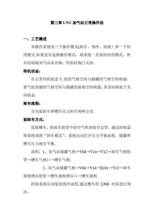
1、加液机的结构:加液机由机壳、电脑控制器、压力传感器、防爆接线盒、入口截止阀、安全阀、质量流量计、电磁阀、单向阀、真空软管、加液枪座、加液枪头及无缝不锈钢管和不锈钢接头等部件组成。
LNG加液机结构图(1.壳体 2、真空软管 3、压力传感器 4、加液枪头 5、加液枪座 6、单向阀7、电磁阀 8、质量流量计 9、安全阀 10.截止阀 11、接线盒)2、工作原理:液化天然气经过输送管道进入加液机,依次流经入口截止阀、安全阀、质量流量计、电磁阀、单向阀、真空软管、加液枪头,最后流入被充液汽车的真空瓶。
质量流量计测出流经加液机的气体的密度、质量等参数的物理信号,由信号转换器转换成电脉冲信号传送到电脑控制器,电脑经自动计算得出相应的体积(质量)、金额并由显示屏显示给用户,从而完成一次加液计量过程。
二、加液机加液安全操作规程:1、作业前准备(1)由运行工负责潜液泵、加液管路、加液机的预冷。
(2)首先检查储罐压力及液位是否满足潜液泵的运行要求。
(3)检查仪表空气系统是否工作正常,有无泄漏点。
(4)从控制电脑界面“参数位置”选中“LNG加气”,潜液泵进液,回气,出口紧急切断阀即气动打开,开始预冷潜液泵,潜液泵预冷温度设置为-115℃。
LNG潜液泵说明

A pump is a pump,right? No t exactly,given all the variations on thetheme. Take, for example thosepumps primarily used for trans-fer of liquefied natural gas (LNG)and o ther liquefied gases. They’rereally in a class unto themselves.Over the years, various methods oftransferring LNG fro m ship to tankstorage for transfer later to a send-outsystem, or transfer directly from shipinto a regasificatio n o r send-o ut sys-tem have been studied, and some arealready in detailed design o r underco nstructio n. This article fo cuses o nthe use of submerged, electric motorpumps (SEMPs) fo r these types o fservices.Multistage LNG send-out pumpafter removal from test stand Submerged Motor32MAY 2004 PUMPS & SYSTEMSAlong with the rapid growth of the global LNG market has c ome an esc alating demand for additional LNG receiving termi-nals and regasific ation systems around the world. Suc h termi-nals, whether on- or offshore,contain gas send-out systems that utilize SEMPs for LNG transfer and pressurization. These pumps typically feature an integral shaft with the entire motor, bearings and all other c omponents c om-pletely flooded with LNG. SafetySubmerged motor pump tec hnology was first applied in LNG applic ations in the early 1960s. Sinc e that time, SEMPS have been used in almost all LNG rec eiving terminals. The main reason for their popularity is their inherently safe design ompared to that of external motor type pumps with dynamic shaft seals.The motor and hydraulic sections of the SEMP are directly c oupled with a c ommon shaft,submerged in the liquid, with no oxygen present. This means the motor is not located in the atmo-sphere in the hazardous area, and no rotating seals are required.The design almost c ompletely eliminates the possibility of leak-age of flammable gas into the atmosphere.In addition to the safety aspe c ts, as no coupling is required between the motor and pump sec tions, there are no alignment problems normally assoc iated with pumps that use ouplings. Furthermore, sinc e the c omplete assembly is sub-merged in liquid that ac ts as effec tive sound insulation, these pumps operate very quietly.Basic DesignIn a traditional, land-based LNG receiving terminal, the sys-tem c onsists of a storage tankthat contains retractable (remov-able) or in-tank type pumps, and a send-out system, whic h c on-tains vessel-mounted type high-pressure LNG pumps and vapor-izers. This type of terminal also inc ludes a jetty where the LNG carrier would dock and discharge its LNG into the onshore storage tanks.The pumps used in the onshore storage tanks are sub-merged motor, retractable types,as shown in Figure 1. For a typi-c al rec eiving terminal, this type pump, sometimes also referred to as a “primary” pump, will have a flow rate of approximately 200 to over 400 m 3/h. This pump would normally only require one or two impeller stages, as it only needs to transfer the LNG out of the tank and into the secondary sys-tem.For vaporizer-feed duty, a relatively high pressure is required due to the high-pressure drop ac ross the vaporizer. For this application, a multistage ves-sel-mounted type pump (see Figure 2) that can produce pres-sures up to approximately 140kg/cm 2is used.For primary transfer pumps,the motor voltage is normally 400 to 480 volts, three phase, but also can be made at higher volt-ages, depending on the site power supply. The sec ondary vaporizer-feed pumps are nor-mally higher power, whi c h require from 4160 to 6600 volts.Both types of pumps c an be manufactured for either 50 or 60Hz power, depending on site requirements.The primary pump is installed into the storage tank through a disc harge “c olumn”mounted inside the tank. At the base of the c olumn is a suc tion valve that is opened by the pump itself. As the pump is lowered into the tank, the valve opens,allowing the LNG to flow intothe inlet of the pump. The pump has a seal loc ated near its base,which allows the discharge liquid to be pumped out the top of the pump and out the top of the dis-charge column.Sinc e the primary pump is installed in the storage tank,which is already provided with a vent system, no other venting c onnec tion at the headplate or olumn is required (although venting of the column to equal-ize pressure to the main tank area is required prior to start-up). The heat from the pump primarily is transferred to the pumped fluid,with only a small amount of heat being transferred back to the liq-uid in the storage tank.The high-pressure secondary pump is installed in its own self-ontained suc tion vessel, withPUMPS & SYSTEMS MAY 200433Figure 1.Diagram of submerged motor,retractable (removable) ty pe pumpused simply to transfer the LNG to Array the send-out system. Normally, twoor three primary pumps are used,depending on total flow require-ments and the need for backup orredundancy. From a pump designstandpoint, there is no particularspacing requirement between thepump columns. Normally, the col-umn spacing will be dictated by thetank design and spacing of the pip-ing, valves, etc, at the tank top.Care should be tak en in thetank design for the location of theinlet piping to the tank. If the inletpipe is placed too close to the pumpcolumns, the warmer liquid enter-ing the tank can affect the NPSHRof the pumps when filling the tanksduring lower-level operation.Another requirement is theneed for column venting prior tostart-up. Most columns will havedischarge piping that can be ventedto the tank top to equalize pressurebetween the tank and column; it iscrucial to ensure there are no lowspots that could trap liquid orprevent proper venting. ThisFigure 2.Multistage vessel-mounted pump design for vaporizer-feed duty.PUMPS & SYSTEMSealso is critical to recognize proper v nting. Sinc th s condary pumps normally hav much higher motor power, it is particu-larly important to take care of any heated LNG or vapor. Vent line s should always be rising as the y le ave the pump ve sse l and provide good ve nting back to a low-pre ssure space. Many prob-lems with secondary pumps over the years have been attributed to poor vent-system design.In the se condary pump sys-tem, a phase separator, or recon-de nse r, is normally installe d in the suction area. This tank is typ-ically used to allow the liquid to se ttle long e nough to allow any vapor to be ve nte d, and is also used to introduce LNG from the boil-off gas syste m to try and re cove r as much of the LNG as possible. The de sign of the sys-te m in this are a should also be tre ate d care fully to e nsure that the LNG temperature is still wellinto the liquid phase as it entersthe pump suction.MotorsWith the re ce nt inte re st in offshore or remote send-out sys-te ms, an important topic is the electrical supply used to start the high-pre ssure se nd-out pumps.Since the motors in these pumps are typically from 1000 to as much as 2300 kW, a large start-ing syste m is re quire d. A cryo-ge nic motor is a unique de sign,and the starting current required is approximately 61⁄2times the full load curre nt. It is difficult to re duce this value be cause of the amount of torque re quire d for starting a cryogenic motor.To re duce the starting cur-rent, soft starters, autotransform-ers and variable frequency drives can be use d with SEMPs—and have been used very successfully in many applications. Howe ve r,proper set-up of starting parame-ters in any current reduction type starting system is critical. T o pre-v nt probl ms, consult your pump manufacturer.In some offshore or re mote locations, using the LNG carrier as the primary system delivering the LNG dire ctly to the se c-ondary pumps has be n dis-cussed. It appears as though the biggest obstacle in this type sys-te m is the ve nting and boil-off from the send-out system during operation. Using the boil-off gas to feed local gas turbine genera-tors for powe r, or pre ssurizing the gas using compre ssors and feeding into the downstream gas syste m appe ar to be popular alternatives.Monitor & ProtectBoth primary and secondary SEMPs can have monitoring sys-tems installed to trend vibration.These systems typically consist of a piezoelectric type accelerometerPUMPS & SYSTEMS MAY 2004 35C i r c l e 226o n R e a d e r S e r v i c e C a r dMAY 2004 PUMPS & SYSTEMS36■Operation at flow rates away fr om the r ated or best effi-ciency point fo extended periods of time.■Debr is or contamination in the liquid.Since LNG systems are nor-mally clean, the first two points seem to be the main causes of failur e. To ensur e r eliable send-out systems, the designer s and oper ator s of these systems need to be well tr ained and awar e of the important issues surrounding design and operation.Mo r eove r, it is especially impor tant to consult with the SEMP manufacturer during ini-tial design or FEED stages, aswell as when wr iting specifica-tions for equipment. As with any application, p r ope rsystem design should r esult in a safe,simple, r eliable and r easonably priced installation. P&SReferences1. D. Cullen, J. Madison, HighPressure T echnology, Hydro-carbon Asia, July/August 2001.2. G. Louis Weisser, ModernSubmersible Pumps for Cryogenic Liquids, World Pumps, January 1994.3. D. Cullen, S. Rush, J. Madison,Radial and Axial Diffusers for S ubmerged Electric Motor-Driven Pumps, World Pumps,September 2000.Steve Rush is the Vice President of S ales and Service for the Cryodynamics Division of Ebara International Corp (EIC).Headquartered in Sparks, NV, he’s worked with this division for more than 23 years in the design, devel-opment, testing, service and sales of submerged motor cryogenic pumps and liquid expanders. The author of several papers and articles on various subjects related to liquefied gas pump equipment manufac-tured by EIC/Cryodynamics, Rush based this article on a presentation he delivered for the 2004 AIChE Spring National Meeting, T opical Conference on Natural Gas Utili-zation, in New Orleans, LA, April 27th. Contact him directly at:srush@PUMPS & SYSTEMS MAY 2004 37C i r c l e 248o n R e a d e r S e r v i c e C a r d。
LNG加气站操作规程

LNG加气站操作规程一、安全操作要求1.操作人员必须经过专业培训,并取得相关资格证书,了解LNG的基本性质、危险特性和操作规程。
2.操作人员必须佩戴符合国家标准的个人防护装备,并按照规定穿戴工作服,并保持整洁和统一3.操作人员必须保持警觉,不得擅自离开工作岗位,发生异常情况时及时报告主管。
4.禁止在加气站内吸烟、明火作业,严禁乱堆物品。
5.加气站内必须安装足够数量和种类的灭火器、消防栓等消防设备,并经常检修和保养。
二、LNG储罐操作规程1.在进行气化和加气作业前,必须检查储罐与加气设备的连接情况,并确保密封、无泄漏。
2.加气操作人员必须清楚了解储罐的安全性能和操作规程,并随时严格按照操作规程进行操作。
3.禁止在储罐周围进行焊接、火焰切割等明火作业。
三、LNG气化设备操作规程1.在进行气化设备起动前,必须检查设备的运行状况,确保无异常。
2.加气站内的气化设备安全组织按照规定检修和保养,并定期进行维护检查。
3.操作人员必须了解气化设备的基本原理和操作方法,并随时掌握其运行状态。
四、LNG加气设备操作规程1.在进行加气作业前,必须检查加气设备的运行状况,确保无异常。
2.加气设备操作人员必须了解加气设备的基本原理和操作方法,并随时掌握其运行状态。
3.加气操作过程中,操作人员必须严格按照操作规程进行操作,严禁超负荷操作。
五、LNG加气作业安全要求1.加气作业前,必须检查加气设备的连接状态和密封性,确保无泄漏。
2.加气作业时,必须注意货车的安装和接地情况,确保安全可靠。
3.加气作业结束后,必须关闭加气设备,并检查设备的连接情况和完好性。
六、应急处置规程1.在发生事故或紧急情况时,操作人员必须立即启动应急预案,采取相应的措施,确保人员安全和设备完好。
2.在应急情况下,必须及时报告相关主管部门,并听从指挥。
3.在应急情况处理完毕后,必须及时进行事故调查和隐患排查,总结经验教训。
七、例行检查和维护1.加气站必须定期进行设备的检查和维护,确保设备的正常运行。
LNG加气站操作规程准则

LNG加气站操作规程准则加气站操作流程标准一、、岗位职责(含生产和安全职责)(1)站长岗位职责1、站长对全站的生产运行、优质服务、行政管理负责,领导全站职工完成公司下达的生产任务;完成公司领导安排的其它有关生产经营管理方面的工作。
2、认真贯彻和执行党和国家的法律、法规及遵守公司制定的各项规章制度,建立健全的正常工作秩序,经常实施定期或不定期检查,及时发现问题,及时解决。
3、根据上级要求及年度计划,制定本站经营目标,并及时落实到生产中去,完成各项年度指标。
4、做好全站人员的思想工作;培养管理人员,提出班长及生管理人员名单。
5、随时检查监督各岗位责任制的落实及操作规程的执行情况,协助相关部门不断完善岗位责任制和操作规程。
6、定期组织人员对设备、管线阀门、仪器仪表、消防重点部位及消防器材、报警装置进行检查、维护、使之始终处于良好状态。
7、组织安排全站职工业务技术和LNG站事故应急抢险预案学习、企业文化和职工道德教育,使其具备正确处理突发事件的综合能力。
8、做好班组人员调配、班组间工作安排和衔接;对值班经理和班组工作定期考核并提出考核和奖惩意见。
9、负责购进及销售气量的结算工作,做到月结月清,监督营业款的上交工作。
10、定期向公司领导汇报LNG加气站工作情况,接受领导的工作检查,执行有关指令。
如遇突发情况必须及时报告,并组织全站人员实施应急抢险并启动应急预案。
11、完成上级领导交办的临时性任务。
(2)站长安全职责1、在经理领导下,LNG加气站站长对全站的安全生产、安全管理全面负责,领导全站职工完成公司下达的安全生产工作任务;完成公司领导安排的其它有安全(生产安全和消防安全)方面的工作。
2、认真学习和贯彻国家的法律法规和公司的安全生产制度,把职业安全列入工作重要议事日程。
3、树立“安全第一”的思想,落实LNG加气站的各项安全制度。
4、做好全站员工的劳动纪律、消防安全、安全知识的教育。
5、随时检查监督岗位责任制的落实及操作规程的执行情况,协助上级部门不断完善岗位责任制和操作规程。
- 1、下载文档前请自行甄别文档内容的完整性,平台不提供额外的编辑、内容补充、找答案等附加服务。
- 2、"仅部分预览"的文档,不可在线预览部分如存在完整性等问题,可反馈申请退款(可完整预览的文档不适用该条件!)。
- 3、如文档侵犯您的权益,请联系客服反馈,我们会尽快为您处理(人工客服工作时间:9:00-18:30)。
LNG加气站潜液泵操作
规程示范文本
In The Actual Work Production Management, In Order To Ensure The Smooth Progress Of The Process, And Consider The Relationship Between Each Link, The Specific Requirements Of Each
Link To Achieve Risk Control And Planning
某某管理中心
XX年XX月
LNG加气站潜液泵操作规程示范文本使用指引:此操作规程资料应用在实际工作生产管理中为了保障过程顺利推进,同时考虑各个环节之间的关系,每个环节实现的具体要求而进行的风险控制与规划,并将危害降低到最小,文档经过下载可进行自定义修改,请根据实际需求进行调整与使用。
(一)目的
为确保操作及管理人员安全的使用本设备,保证加气
站的安全运行。
(二)适应范围
本LNG加注设施区域内的LNG潜液泵及泵体附属设
备。
(三)操作规程
(1)开机前的检查:
a) 检查所有的管路、配件、螺栓和电路接线是否准备
就绪。
b) 检查所有管路接头部位的密封情况是否达到要求。
c) 检查储罐液位与泵吸入口是否有足够的液位差。
(2)启动:
a) 按照潜液泵的预冷程序,缓慢地对泵进行冷却。
b) 预冷完成后,泵壳内充满液体。
当泵池温度测点温度低于设定值之后,变频器按照给定频率启动电机。
c) 如果泵发出异常的声音,或排出管路有较大震动,应立即停泵,查找出原因后,重新启动。
(3)停泵:
a) 切断泵的变频输出,关闭进液阀,导通加气机回流管线。
b) 常开回气阀门,确保回气畅通。
(4)注意事项:
a) 必须密切关注泵的气蚀问题,即良好控制启泵温度,关注泵出口压力,避免严重气蚀给现场操作人员带来人身伤害或给设备带来损害。
b) 当泵不起压时,首先判断泵是否转动,若泵不转,
先查找动力电源及变频器问题,若正常,则考虑泵本体机械发生故障。
若判断泵转动,则根据泵运行声音正常与否,判断是否为液体原因或是电源因素,若均正常,则考虑泵本体机械发生故障。
当泵起压后压力不平稳,起伏波动时,先判断管路管阻是否发生变化(即进、出口阀门和加气机阀门是否正常开启),若均正常,则先考虑变频器频率是否恒定,最后考虑泵本体机械发生故障。
c) 依据气瓶压力的不同酌情选择加气机运行频率,在气瓶压力大于0.8MPa时,建议回气卸压,以确保加气速度及泵在较好工况工作。
d) 当泵的转速不为“0”时,请勿二次启动电机。
请在此位置输入品牌名/标语/slogan
Please Enter The Brand Name / Slogan / Slogan In This Position, Such As Foonsion。