橡胶制品压缩永久变形测试
d395橡胶压缩永久变形特性试验方法
Designation:D395–02Standard Test Methods forRubber Property—Compression Set1This standard is issued under thefixed designation D395;the number immediately following the designation indicates the year of original adoption or,in the case of revision,the year of last revision.A number in parentheses indicates the year of last reapproval.A superscript epsilon(e)indicates an editorial change since the last revision or reapproval.This standard has been approved for use by agencies of the Department of Defense.1.Scope1.1These test methods cover the testing of rubber intended for use in applications in which the rubber will be subjected to compressive stresses in air or liquid media.They are applicable particularly to the rubber used in machinery mountings,vibra-tion dampers,and seals.Two test methods are covered as follows:Test Method Section A—Compression Set Under Constant Force in Air7–10B—Compression Set Under Constant Deflection in Air11–14 1.2The choice of test method is optional,but consideration should be given to the nature of the service for which correlation of test results may be sought.Unless otherwise stated in a detailed specification,Test Method B shall be used.1.3Test Method B is not suitable for vulcanizates harder than90IRHD.1.4The values stated in SI units are to be regarded as the standard.1.5This standard does not purport to address all of the safety concerns,if any,associated with its use.It is the responsibility of the user of this standard to establish appro-priate safety and health practices and determine the applica-bility of regulatory limitations prior to use.2.Referenced Documents2.1ASTM Standards:D1349Practice for Rubber—Standard Temperatures for Testing2D3182Practice for Rubber—Materials,Equipment,and Procedures for Mixing Standard Compounds and Prepar-ing Standard Vulcanized Sheets2D3183Practice for Rubber—Preparation of Pieces for Test Purposes from Products2D3767Practice for Rubber—Measurement of Dimensions2 D4483Practice for Determining Precision for Test Meth-ods Standards in the Rubber and Carbon Black Industries2E145Specification for Gravity-Convection and Forced-Ventilation Ovens33.Summary of Test Methods3.1A test specimen is compressed to either a deflection or by a specified force and maintained under this condition for a specified time and at a specified temperature.3.2The residual deformation of a test specimen is measured 30min after removal from a suitable compression device in which the specimen had been subjected for a definite time to compressive deformation under specified conditions.3.3After the measurement of the residual deformation,the compression set,as specified in the appropriate test method,is calculated according to Eq1and Eq2.4.Significance and Use4.1Compression set tests are intended to measure the ability of rubber compounds to retain elastic properties after pro-longed action of compressive stresses.The actual stressing service may involve the maintenance of a definite deflection, the constant application of a known force,or the rapidly repeated deformation and recovery resulting from intermittent compressive forces.Though the latter dynamic stressing,like the others,produces compression set,its effects as a whole are simulated more closely by compressionflexing or hysteresis tests.Therefore,compression set tests are considered to be mainly applicable to service conditions involving static stresses.Tests are frequently conducted at elevated tempera-tures.5.Test Specimens5.1Specimens from each sample may be tested in duplicate (Option1)or triplicate(Option2).The compression set of the sample in Option1shall be the average of the two specimens expressed as a percentage.The compression set of the sample in Option2shall be the median(middle most value)of the three specimens expressed as a percentage.5.2The standard test specimen shall be a cylindrical disk cut from a laboratory prepared slab.5.2.1The dimensions of the standard specimens shall be:1These test methods are under the jurisdiction of ASTM Committee D11onRubber and are the direct responsibility of Subcommittee D11.10on PhysicalTesting.Current edition approved Dec.10,2002.Published January2003.Originallyapproved st previous edition approved in2001as D395–01.2Annual Book of ASTM Standards,V ol09.01.3Annual Book of ASTM Standards,V ol14.04.1Copyright©ASTM International,100Barr Harbor Drive,PO Box C700,West Conshohocken,PA19428-2959,United States.Type1A2BThickness,mm(in.)12.560.5(0.4960.02)6.060.2 (0.2460.01)Diameter,mm(in.)29.060.5(1.1460.02)13.060.2 (0.5160.01)A Type1specimen is used in Test Methods A and B.B Type2specimen is used in Test Method B.5.2.2When cutting the standard specimen,the circular die having the required inside dimensions specified in5.2.1shall be rotated in a drill press or similar device and lubricated by means of a soap solution.A minimum distance of13mm(0.51 in.)shall be maintained between the cutting edge of the die and the edge of the slab.The cutting pressure shall be as light as possible to minimize cupping of the cut edges.The dies shall be maintained carefully so that the cutting edges are sharp and free of nicks.5.3An optional method of preparing the standard specimen may be the direct molding of a circular disk having the dimensions required for the test method used and specified in 5.2.1.N OTE1—It should be recognized that an equal time and temperature,if used for both the slab and molded specimen,will not produce an equivalent state of cure in the two types of specimen.A higher degree of cure will be obtained in the molded specimen.Adjustments,preferably in the time of cure,must be taken into consideration if comparisons between the specimens prepared by different methods are to be considered valid. N OTE2—It is suggested,for the purpose of uniformity and closer tolerances in the molded specimen,that the dimensions of the mold be specified and shrinkage compensated for therein.A two-plate mold with a cavity13.060.1mm(0.51060.004in.)in thickness and29.2060.05 mm(1.14860.002in.)in diameter,with overflow grooves,will provide Type1specimens for Test Method A and Test Method B.A similar mold but having a cavity of6.360.3mm(0.2560.012in.)in thickness and 13.260.1mm(0.5260.004in.)in diameter will provide Type2 specimens for Test Method B.5.4When the standard test specimen is to be replaced by a specimen taken from a vulcanized rubber part of greater thickness than the one indicated in5.2.1,the sample thickness shall be reducedfirst by cutting transversely with a sharp knife and then followed by buffing to the required thickness in accordance with Practice D3183.5.5An alternative method of preparing specimens is by plying up cylindrical disks cut from a standard sheet prepared in accordance with Practice D3182using the specimen sizes specified in5.2.1and cutting as described in5.2.2,or where a drill press is not available cutting the specimens with a single stroke from a cutting die.5.5.1The disks shall be plied,without cementing,to the thickness required.Such plies shall be smooth,flat,of uniform thickness,and shall not exceed seven in number for Type1 specimens and four in number for Type2specimens.5.5.2Care shall be taken during handling and placing of the plied test specimen in the testfixture by keeping the circular faces parallel and at right angles to the axis of the cylinder.5.5.3The results obtained on plied specimens may be different from those obtained using solid specimens and the results may be variable,particularly if air is trapped between disks.5.5.4The results obtained on the specimens prepared by one of the methods may be compared only to those prepared by the same method.5.6For routine or product specification testing,it is some-times more convenient to prepare specimens of a different size or shape,or both.When such specimens are used,the results should be compared only with those obtained from specimens of similar size and shape and not with those obtained with standard specimen.For such cases,the product specification should define the specimen as to the size and shape.If suitable specimens cannot be prepared from the product,the test method and allowable limits must be agreed upon between the producer and the purchaser.6.Conditioning6.1Store all vulcanized test specimens or product samples to be tested at least24h but not more than60days.When the date of vulcanization is not known,make tests within60days after delivery by the producer of the article represented by the specimen.6.2Allow buffed specimens to rest at least30min before specimens are cut for testing.6.3Condition all specimens before testing for a minimum of 3h at2362°C(73.463.6°F).Specimens whose compression set properties are affected by atmospheric moisture shall be conditioned for a minimum of24h in an atmosphere controlled to5065%relative humidity.7.Precision and Bias47.1These precision statements have been prepared in ac-cordance with Practice D4483.Please refer to Practice D4483 for terminology and other testing and statistical concepts.7.2Prepared test specimens of two rubbers for Test MethodsA andB were supplied tofive laboratories.These were tested in duplicate each day on two separate testing days.A test result, therefore,is the average of two test specimens,for both Test Methods A and B.7.3One laboratory did not run the Test Method A testing; therefore,the precision for Test Method A is derived from four laboratories.7.4The Type1precision results are given in Table1and Table2.4Supporting data are available from ASTM Headquarters.Request RR: D11–1138.TABLE1Type1Precision Results,%Compression Set—TestMethod AMaterialMeanLevelWithin Laboratory A Between Laboratory AS r r(r)S R R(R)1 1.73(%)0.0500.1428.20.1900.5431.1 226.10.898 2.549.7 2.37 6.7125.7A Sr=within laboratory standard deviation.r=repeatability(in measurement units).(r)=repeatability(in percent).S R=between laboratory standard deviation. R=reproducibility(in measurement units). (R)=reproducibility(in percent).7.5Bias—In test method statistical terminology,bias is the difference between an average test value and the reference or true test property value.Reference values do not exist for these test methods since the value or level of the test property is exclusively defined by the test method.Bias,therefore,cannot be determined.TEST METHOD A—COMPRESSION SET UNDERCONSTANT FORCE IN AIR8.Apparatus8.1Dial Micrometer—A dial micrometer,for measuring specimen thickness,in accordance with Practice3767,Method A1.8.2Compression Device,consisting of a force application spring and two parallel compression plates assembled bymeans of a frame or threaded bolt in such a manner that the device shall be portable and self-contained after the force has been applied and that the parallelism of the plates shall be maintained.The force may be applied in accordance with either 8.2.1or8.2.2.8.2.1Calibrated Spring Force Application—The required force shall be applied by a screw mechanism for compressing a calibrated spring the proper amount.The spring shall be of properly heat-treated spring steel with ends ground and per-pendicular to the longitudinal axis of the spring.A suitable compression device is shown in Fig. 1.The spring shall conform to the following requirements:8.2.1.1The spring shall be calibrated at room temperature 2365°C(73.469°F)by applying successive increments of force not exceeding250N(50lbf)and measuring the corresponding deflection to the nearest0.2mm(0.01in.).The curve obtained by plotting the forces against the corresponding deflections shall have a slope of7063.5kN/m(400620 lbf/in.)at1.8kN(400lbf).The slope is obtained by dividing the two forces above and below1.8kN by the difference between the corresponding deflections.8.2.1.2The original dimensions of the spring shall not change due to fatigue by more than0.3mm(0.01in.)after it has been mounted in the compression device,compressed under a force of1.8kN(400lbf),and heated in the oven for one week at70°C62°C(15863.6°F).In ordinary use,a weekly check of the dimensions shall show no greater change than this over a period of1year.8.2.1.3The minimum force required to close the spring (solid)shall be2.4kN(530lbf).8.2.2External Force Application—The required force shall be applied to the compression plates and spring by external means after the test specimen is mounted in the apparatus. Either a calibrated compression machine or known masses may be used for force application.Provision shall be made by the use of bolts and nuts or other devices to prevent the specimen and spring from losing their initial deflections when the external force is removed.The spring shall have essentially the same characteristics as described in8.2.1,but calibration is not required.A suitable compression device is shown in Fig.2.8.3Plates—The plates between which the test specimen is compressed shall be made of steel of sufficient thickness to withstand the compressive stresses without bending.8.3.1The surfaces against which the specimen is held shall have a chromium platedfinish and shall be cleaned thoroughly and wiped dry before each test.8.3.2The steel surfaces contacting the rubber specimens shall be ground to a maximum roughness of250µm(10µin.) and then chromium plated and polished.8.3.3The chromium plating and subsequent polishing shall not affect thefinalfinish beyond the tolerance stated in8.3.2.8.4Oven,conforming to the specification for a Type IIB laboratory oven given in Specification E145.8.4.1Type IIB ovens specified in Test Method E145are satisfactory for use through70°C.For higher Temperatures Type II A ovens are necessary.8.4.2The interior size shall be as follows or of an equivalent volume:TABLE2Type1Precision Results,%Compression Set—TestMethod BMaterial MeanLevelWithin Laboratory A Between Laboratory AS r r(r)S R R(R)113.7(%)0.591 1.6712.2 1.54 4.3631.8 252.80.567 1.60 3.0 5.9216.831.7 A Sr=within laboratory standard deviation.r=repeatability(in measurement units).(r)=repeatability(in percent).S R=between laboratory standard deviation.R=reproducibility(in measurement units).(R)=reproducibility(in percent).Interior size of air oven:min.300bt300mm by300mm(12by12by12in.)max.900by900by1200mm(36by36by48in.) 8.4.3Provision shall be made for placing test specimens in the oven without touching each other or the sides of the aging chamber.8.4.4The heating medium for the aging chamber shall be air circulated within it at atmospheric pressure.8.4.5The source of heat is optional but shall be located in the air supply outside of the aging chamber.8.4.6A suitable temperature measurement device located in the upper central portion of the chamber near the test speci-mens shall be provided to record the actual aging temperature.8.4.7Automatic temperature control by means of thermo-static regulation shall be used.8.4.8The following special precautions shall be taken in order that accurate,uniform heating is obtained in all parts of the aging chamber.8.4.8.1The heated air shall be thoroughly circulated in the oven by means of mechanical agitation.When a motor driven fan is used,the air must not come in contact with the fan motor brush discharge because of danger of ozone formation.8.4.8.2Baffles shall be used as required to prevent local overheating and dead spots.8.4.8.3The thermostatic control device shall be so located as to give accurate temperature control of the heating medium. The preferred location is adjacent to the temperature measuring device listed in section8.4.6.8.4.8.4An actual check shall be made by means of maxi-mum reading thermometers placed in various parts of the oven to verify the uniformity of the heating.9.Procedure9.1Original Thickness Measurement—Measure the original thickness of the specimen to the nearest0.02mm(0.001in.). Place the specimen on the anvil of the dial micrometer so that the presser foot will indicate the thickness at the central portion of the top and bottom faces.9.2Application of Compressive Force—Assemble the specimens in the compression device,using extreme care to place them exactly in the center between the plates to avoid tilting.If the calibrated spring device(see Fig.1)is used,apply the compressive force by tightening the screw until the deflection as read from the scale is equivalent to that shown on the calibration curve for the spring corresponding to a force of 1.8kN(400lbf).With the external loading device(see Fig.2), apply this force to the assembly in the compression machine or by adding required masses,but in the latter case,take care to add the mass gradually without shock.Tighten the nuts and bolts just sufficiently to hold the initial deflections of the specimen and spring.It is imperative that no additional force be applied in tightening the bolts.9.3Test Time and Test Temperature—Choose a suitable temperature and time for the compression set,depending upon the conditions of the expected service.In comparative tests,use identical temperature and heating periods.It is suggested that the test temperature be chosen from those listed in Practice D1349.Suggested test periods are22h and70h.The specimen shall be at room temperature when inserted in the compression device.Place the assembled compression device in the oven within2h after completion of the assembly and allow it to remain there for the required test period in dry air at the test temperature selected.At the end of the test period,take the device from the oven and remove the specimens immedi-ately and allow it to cool.9.4Cooling Period—While cooling,allow the specimens to rest on a poor thermally conducting surface,such as wood,for 30min before making the measurement of thefinal thickness. Conduct the cooling period at a standard laboratory tempera-ture of2362°C(73.463.6°F).Specimens whose compres-sion set property is affected by atmospheric moisture shall be cooled in an atmosphere controlled to5065%relative humidity.9.5Final Thickness Measurement—After the rest period, measure thefinal thickness at the center of the specimen in accordance with9.1.10.Calculation10.1Calculate the compression set as a percentage of the original thickness as follows:C A5@~t o2t i!/t o#3100(1) where:C A=Compression set(Test Method A)as a percentage ofthe original thickness,t o=original thickness(see9.1),andt i=final thickness (see 9.5).11.Report11.1Report the following information:11.1.1Original dimensions of the test specimen,including the original thickness,t o ,11.1.2Actual compressive force on the specimen as deter-mined from the calibration curve of the spring and spring deflection reading (see 8.2.1)or as applied by an external force (see 8.2.2),11.1.3Thickness of the test specimen 30min after removal from the clamp,t i ,11.1.4Type of test specimen used,together with the time and temperature of test,11.1.5Compression set,expressed as a percentage of the original thickness,11.1.6Test method used (Test Method A),and 11.1.7Number of specimens tested.TEST METHOD B—COMPRESSION SET UNDERCONSTANT DEFLECTION IN AIR 12.Apparatus12.1Dial Micrometer —A dial micrometer,for measuring the specimen thickness,in accordance with Practice D 3767,Method A 1.N OTE 3—For vulcanizates having a hardness below 35IRHD,the force on the presser foot should be reduced to 0.260.05N (0.0460.01lbf).12.2Spacer Bars ,to maintain the constant deflection re-quired under Test Method B.12.2.1Spacer bars for Type 1samples shall have a thickness of 9.560.02mm (0.37560.001in.).12.2.2Spacer bars for Type 2samples shall have a thickness of 4.5060.01mm (0.177060.0005in.).12.3Compression Device ,consisting of two or more flat steel plates between the parallel faces of which the specimens may be compressed as shown in Fig.3.Steel spacers for the required percentage of compression given in 13.2shall be placed on each side of the rubber specimens to control their thickness while compressed.12.4Oven ,see 8.4.12.5Plates —The plates between which the test specimen is compressed shall be made of steel of sufficient thickness to withstand the compressive stresses without bending.12.5.1The surfaces against which the specimen is held shall have a chromium-plated finish and shall be cleaned thoroughly and wiped dry before each test.12.5.2The steel surfaces contacting the rubber specimens shall be ground to a maximum roughness of 250µm (10µin.)and then chromium plated and polished.12.5.3The chromium plating and subsequent polishing shall not affect the final finish beyond the tolerance stated in 12.5.2.13.Procedure13.1Original Thickness Measurement —Measure the origi-nal thickness of the specimen to the nearest 0.02mm (0.001in.).Place the specimen on the anvil of the dial micrometer so that the presser foot will indicate the thickness at the central portion of the top and bottom faces.13.2Application of Compressive Force —Place the test specimen between the plates of the compression device with the spacers on each side,allowing sufficient clearance for the bulging of the rubber when compressed (see Fig.3).Where a lubricant is applied,it shall consist of a thin coating of a lubricant having substantially no action on the rubber.For most purposes,a silicon or fluorosilicon fluid is suitable.Tighten the bolts so that the plates are drawn together uniformly until they are in contact with the spacers.The amount of compression employed shall be approximately 25%.A suitable mechanical or hydraulic device may be used to facilitate assembling and disassembling the test fixture.13.3Test Time and Temperature —Choose a suitable tem-perature and time for the compression set,depending upon the conditions of the expected service.In comparative tests,use identical temperature and test periods.It is suggested that the test temperature be chosen from those listed in Practice D 1349.Suggested test periods are 22h and 70h.The test specimen shall be at room temperature when inserted in the compression device.Place the assembled compression device in the oven within 2h after completion of the assembly and allow it to remain there for the required test period in dry air at the test temperature selected.At the end of the test period,take the device from the oven and remove the test specimen immediately and allow them to cool.13.4Cooling Period —While cooling,allow the test speci-men to rest on a poor thermally conducting surface,such as wood,for 30min before making the measurement of the final thickness.Maintain the conditions during the cooling period in accordance with 9.4.13.5Final Thickness Measurement —After the rest period,measure the final thickness at the center of the test specimen in accordance with 13.1.14.Calculation14.1Calculate the compression set expressed as a percent-age of the original deflection as follows:C B 5@~t o 2t i !/~t o 2t n !#3100(2)where:C B =compression set (Test Method B)expressed aspercentage of the original deflection,t 0=original thickness of specimen (13.1),t i =final thickness of specimen (13.5),and t n =thickness of the spacer bar used.N OTE 4—Lubrication of the operating surfaces of thecompressionFIG.3Device for Compression Set Test Under ConstantDeflection,Test MethodBdevice is optional while giving more reproducible results;lubrication may somewhat alter the compression set values.15.Report15.1Report the following information:15.1.1Original dimensions of the test specimen including the original thickness,t o,15.1.2Percentage compression of the specimen actually employed,15.1.3Thickness of the test specimen30min after removal from the clamp,t i,15.1.4Type of test specimen used,together with the time and temperature of test,15.1.5Whether or not the surfaces of the compression device are lubricated.If they are,what type lubrication was used,15.1.6Compression set,expressed as a percentage of the original deflection,15.1.7Test method used(Test Method B),and15.1.8Number of specimens tested.16.Keywords16.1compression set;compression set under constant de-flection;compression set under constant force;deflection; deformation;elastic property;hysteresis;recoveryASTM International takes no position respecting the validity of any patent rights asserted in connection with any item mentioned in this ers of this standard are expressly advised that determination of the validity of any such patent rights,and the risk of infringement of such rights,are entirely their own responsibility.This standard is subject to revision at any time by the responsible technical committee and must be reviewed everyfive years and if not revised,either reapproved or withdrawn.Your comments are invited either for revision of this standard or for additional standards and should be addressed to ASTM International Headquarters.Your comments will receive careful consideration at a meeting of the responsible technical committee,which you may attend.If you feel that your comments have not received a fair hearing you should make your views known to the ASTM Committee on Standards,at the address shown below.This standard is copyrighted by ASTM International,100Barr Harbor Drive,PO Box C700,West Conshohocken,PA19428-2959, United States.Individual reprints(single or multiple copies)of this standard may be obtained by contacting ASTM at the above address or at610-832-9585(phone),610-832-9555(fax),or service@(e-mail);or through the ASTM website().。
橡胶密封性能分析——测试方法比较
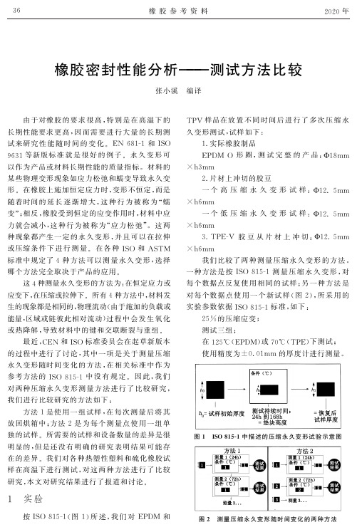
显示了每 3 次测 量 的 平 均 值,误 差 条 显 示 了 最 高
分布的匹配情况.图中绘制了最大值和最小值的
最佳拟合线,以查看测量值的趋势是否存在偏差.
38
橡 胶 参 考 资 料
曲线.
2020 年
最佳拟合线是幂律曲线.
第二项研究用低压缩永久变形和高压缩永久
图 5 示出 了 高 压 缩 永 久 变 形 EPDM 橡 胶 的
对每个数据 点 使 用 一 个 新 试 样 (图 2),所 采 用 的
实验参数依据I
SO815
G
1 标准,如Байду номын сангаас:
25% 的压缩应变;
测试三组;
在 125℃ (
EPDM)或 70℃ (
TPE)下测试;
使用精度为 ±0.
01mm 的厚度计进行测量.
参考方法的 I
SO815
G
1 中 没 有 规 定. 因 此,我 们
分布更真实,因 而 结 果 更 加 精 确.如 果 只 测 试 一
的,因 为 方 法 1 中 每 个 测 量 点 都 有 急 速 冷 却.这
方法 2 的潜在优 点 是 由 于 使 用 了 更 多 试 样,结 果
热条件外,两种方 法 中 影 响 结 果 的 参 数 都 是 相 同
个测试时间,这两种方法之间没有区别,因为测试
36
橡 胶 参 考 资 料
2020 年
橡胶密封性能分析 ——— 测试方法比较
张小溪 编译
由于对橡胶 的 要 求 很 高,特 别 是 在 高 温 下 的
长期性能要求更 高,因 而 需 要 进 行 大 量 的 长 期 测
TPV 样品在放 置 不 同 时 间 后 进 行 了 多 次 压 缩 永
橡胶压缩永久变形标准国标

橡胶压缩永久变形标准国标橡胶压缩永久变形是指橡胶材料在受到一定的压力或应力后,会发生不可恢复的变形现象。
这种变形是橡胶材料特有的性质,也是橡胶制品在实际使用中需要考虑的重要因素之一。
为了保证橡胶制品的使用寿命和性能稳定性,国家制定了橡胶压缩永久变形的标准,即国标。
国标是指由国家制定的、对某一特定领域的产品或服务进行统一规范的标准。
对于橡胶压缩永久变形,国标的制定是为了保证橡胶制品在使用过程中不会出现过大的变形,从而影响其功能和性能。
国标对橡胶压缩永久变形进行了严格的限制,规定了橡胶制品在一定的压力或应力下所允许的变形范围。
橡胶压缩永久变形的国标主要包括以下几个方面的内容:1.测试方法:国标对橡胶压缩永久变形的测试方法进行了详细的规定,包括测试样品的制备、测试条件的确定、测试设备的选择和使用等。
这些规定旨在确保测试结果的准确性和可靠性。
2.压力或应力:国标规定了橡胶制品在测试过程中所受到的压力或应力的范围。
这些压力或应力的选择是基于橡胶材料的性能和使用环境的需求,确保测试结果的可比性和可靠性。
3.变形限制:国标规定了橡胶制品在测试过程中所允许的变形范围。
这些变形限制是基于橡胶材料的物理性质和工程实践的需求,确保橡胶制品在使用过程中不会出现过大的变形,从而影响其功能和性能。
4.评定标准:国标规定了橡胶压缩永久变形的评定标准,即根据测试结果对橡胶制品的质量进行评定。
评定标准主要包括合格和不合格两个等级,根据测试结果的符合程度进行判断。
橡胶压缩永久变形的国标的制定对于橡胶制品的生产和应用具有重要的意义。
首先,国标的制定可以确保橡胶制品在使用过程中具有一定的稳定性和可靠性,减少因变形引起的故障和事故。
其次,国标的制定可以促进橡胶制品的技术进步和质量提升,推动橡胶行业的发展和创新。
最后,国标的制定可以提高橡胶制品的质量标准和行业竞争力,提升橡胶制品在市场上的地位和声誉。
橡胶压缩永久变形的国标是为了保证橡胶制品在使用过程中不会出现过大的变形,从而影响其功能和性能。
压缩永久变形中文版

编号:D 395-03橡胶性能的标准试验方法----------压缩永久变形1此项标准在固定编号B 117下发布,紧随编号的数字表示标准采纳的年度,如果是修正,数字表示最后一次修正的年度。
在括号内的数字表示最后一次重申批准的年度。
上标 表示自最后一次修正或重申批准以来的编辑改动。
此项标准已被批准供美国国防部下属机构使用。
1范围1.1本测试方法测试应用中会在气体或液体媒介中承受压力的橡胶。
本测试方法特别适用于在机械固定器件,1.2测试方法可以选择,但是应考虑用于与测试结果关联的实际情况下使用的橡胶的性质。
除非在具体的规范中有其他规定,应使用测试方法B。
1.3测试方法B不适用于硬度大于90IRHD的硫化橡胶。
1.4以国际单位(SI)为单位的数值应被认为是标准。
在括号内的数值起参照作用。
1.5此项标准不包括与其应用有关的所有的安全隐患。
此项标准的使用者有责任在使用前建立合适的安全健康规范以及决定法规限制是否适用2 参考文件2.1 ASTM标准2:D1349 橡胶规范---测试的标准温度D 3182D 3183D 3767D 4483E 145---------------------------------------1此测试方法属于ASTM D 11橡胶委员会的工作范围,是其下属D11.10物理测试子委员会的直接责任。
目前的版本在2008.3.1批准,2008.07出版。
原始的版本在1934年批准。
上一个版本在2003年批准,编号为D395-03.2如需参照ASTM 标准,访问ASTM网站,. 如需要《ASTM标准年鉴》的内容信息,浏览ASTM网站的标准索引页。
3 测试方法概要3.1 用挠力或规定的力压缩试样,并在规定的温度下保持规定的时间。
3.2 在试样在合适的装置内,在规定的条件下经过特定时间的压缩变形后,取出试样,等待30分钟,测量试样的残留变形。
3.3 在测量残留变形后,根据Eq1和Eq2计算压缩永久变形。
橡胶材料的压缩变形率测试方法
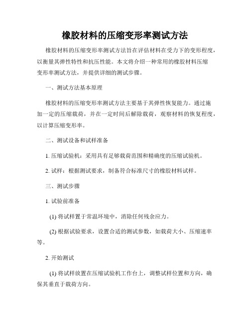
橡胶材料的压缩变形率测试方法橡胶材料的压缩变形率测试方法旨在评估材料在受力下的变形程度,以衡量其弹性特性和抗压性能。
本文将介绍一种常用的橡胶材料压缩变形率测试方法,并提供详细的测试步骤。
一、测试方法基本原理橡胶材料的压缩变形率测试方法主要基于其弹性恢复能力。
通过施加一定的压缩载荷,并在一定时间后解除载荷,观察材料的恢复程度,以计算压缩变形率。
二、测试设备和试样准备1. 压缩试验机:采用具有足够载荷范围和精确度的压缩试验机。
2. 试样:根据测试要求,制备符合标准尺寸的橡胶材料试样。
三、测试步骤1. 试验前准备(1) 将试样置于常温环境中,消除任何残余应力。
(2) 根据试验要求,设置合适的测试参数,如载荷大小、压缩速率等。
2. 开始测试(1) 将试样放置在压缩试验机工作台上,调整试样位置和方向,确保其垂直于载荷方向。
(2) 施加初始压缩载荷,使试样接触承载面。
(3) 在设定的压缩速率下,开始压缩试验,并记录载荷和位移数据。
(4) 持续加载,直到观察到试样的压缩变形达到预定的时间或程度。
3. 解除载荷(1) 解除压缩载荷,使试样恢复到初始状态。
(2) 观察试样的恢复情况,并记录恢复时间和恢复率等数据。
四、数据处理和分析1. 计算压缩变形率压缩变形率可根据以下公式计算:压缩变形率 = (初始高度 - 压缩后高度) / 初始高度 × 100%2. 数据分析和报告对测试数据进行统计和分析,可以绘制压缩变形率-载荷曲线,评估橡胶材料的弹性特性和抗压性能。
将测试结果整理成报告,包括试验条件,数据表格和图表等。
需要注意的是,以上的测试方法仅为一种常用的橡胶材料压缩变形率测试方法,具体的测试方法应根据实际需求和标准要求进行选择。
在进行测试前应熟悉测试设备的操作手册,并遵循实验室安全操作规范。
通过准确的橡胶材料压缩变形率测试方法,可以评估橡胶材料的弹性特性和抗压性能,为材料的选用和工程设计提供科学依据。
2019年硫化橡胶常温、高温下的压缩永久变形试验.doc
2试验结果
压缩永久变形C(%)按式(1)计算:
C(%)=[(h0-h1)/( (h0-h2)]×100……………(1)
式中:h0——试样原高mm
h1----试样恢复后的高度mm
h2————限制器高度mm
计算结果精确到1%
2..2每个试验结果与中值的差不大于士2%或与算术平均值的差不大于士10%,否则再取三个试样试验,结果是取所有试验数据的中值,并在报告中注明试样的个数。
三、成果应用情况、取得的经济效益和社会效益、详细测算或评价依据、远远景预测
四、主要技术文件提供单位和成果完成协作单位
五、成果应用单位财务部门审核意见(能计算直接经济效益的革新成果)
(财务,公章)
年月日
六、申报单位意见
主管领导(签章):
(单位公章)
年月日
七、(力神泵业公司)专业评审组验收意见
(公章)
年月日
橡胶恒定形变压缩永久变形试验监测中心2009年12概要问题的提出及革新目的原技术状况技术指标等橡胶材料受到外力作用时可以产生两种性质的形变?一种是弹性形变即橡胶受外力作用时发生形变当外力除去后便恢复原状?另一种是塑性形变即橡胶受外力作用时发生的形变外力去除后不能恢复原状而有一部分形变保留环的工作状态基本相同
1.7耐液体试验时,先在试验容器内放入液体,液面为容器高度的二分之一,然后把已装有试样的压缩具放入容器内。试样必须浸没在液体中。试验用的液体不能重复使用。不同配方的试样不可在同一试验容器中进行试验。在液体中试验结束后,将试验容器冷却至接近室温,再把压缩夹具从容器中取出,夹具可用汽油等洗涤,时间不超过30 s,然后按本标准7.5.1进行测量,并在报告中注明试验容器的冷却时间。
压缩永久变形
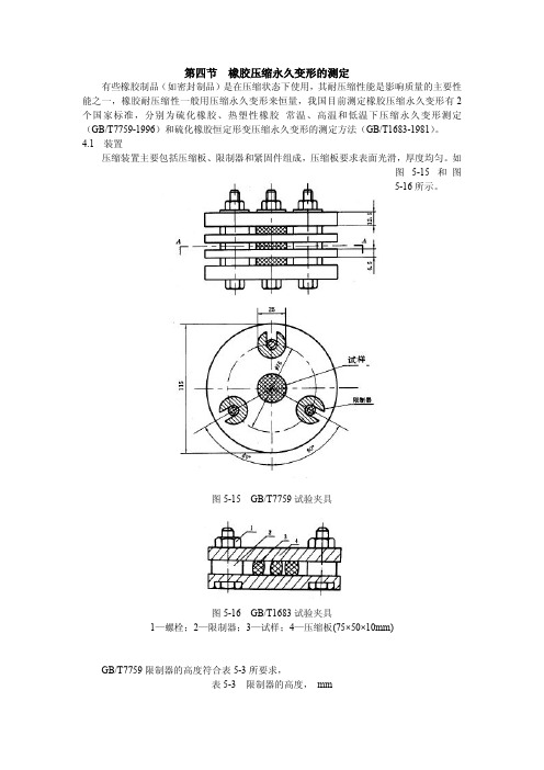
第四节橡胶压缩永久变形的测定有些橡胶制品(如密封制品)是在压缩状态下使用,其耐压缩性能是影响质量的主要性能之一,橡胶耐压缩性一般用压缩永久变形来恒量,我国目前测定橡胶压缩永久变形有2个国家标准,分别为硫化橡胶、热塑性橡胶常温、高温和低温下压缩永久变形测定(GB/T7759-1996)和硫化橡胶恒定形变压缩永久变形的测定方法(GB/T1683-1981)。
4.1装置压缩装置主要包括压缩板、限制器和紧固件组成,压缩板要求表面光滑,厚度均匀。
如图5-15和图5-16所示。
图5-15GB/T7759试验夹具图5-16GB/T1683试验夹具1—螺栓;2—限制器;3—试样;4—压缩板(75×50×10mm)GB/T7759限制器的高度符合表5-3所要求,表5-3限制器的高度,mm试样类型压缩率为25%时压缩率为15%时压缩率为10%时A9.3~9.410.6~10.711.25~11.3B 4.7~4.8 5.3~5.4 5.65~5.7GB/T1683限制器的高度为8±0.02、7±0.02、6±0.02mm。
4.2试样1)试样为圆柱形,GB/T7759试样分为A型和B型两种,A型试样直径为29±0.5mm,高为12.5±0.5mm;B型试样直径为13±0.5mm,高为6.3±0.3mm。
最好用A型试样,B 型试样适用从成品上裁取GB/T1683。
试样直径为10±0.2mm,高为10±0.2mm。
2)试样最好用模具硫化,也可以从胶片或成品上裁取。
3)试样不得有气泡、杂质等。
4)试样的数量为3个。
5)从硫化到试验之间时间不少于16h不超过4周,成品取样为3个月。
制好的试样试验前要在试验标准温度下调节不少于3h。
4.3试验条件⑴试验时间可选用24h、、48h、72h、96h、120h、144h、168h和168h的倍数。
ASDM-低温下的压缩永久变形试验[1]
![ASDM-低温下的压缩永久变形试验[1]](https://img.taocdn.com/s3/m/fca6f7d83186bceb19e8bb77.png)
标准试验方法——橡胶低温下永久变形性能试验1. 范围这个试验方法包括了硫化橡胶性能的评估。
在室温下压缩橡胶,然后在低温下(空气或者二氧化碳)放置,在低温下将其从压接装置中取出,观察其形变回复情况。
1.2 用国际单位制来记录的值即标准值,而括号中的数据只是作为参考使用。
1.3 这个标准没有任何安全隐患。
此测试方法的使用者应注意安全。
2.参考文件2.1 ASTM标准:D375 橡胶性能试验方法——压缩永久变形D832 橡胶性能测试方法——低温测试D3767 橡胶实务——尺寸测量D4483 橡胶和炭黑工业试验方法标准之测试精确度的决定3. 试验方法概述3.1 在室温下,试样将被压缩至它原厚度的25%,然后在设定的低温下放置一段特定时间。
3.2 仍在试验温度下,将此试样恢复(解压)3.3 将试样从压缩仪器中取出后,在10秒和30分钟两个时间点测量其剩余压缩量。
3.4 根据9.1中的公式计算压缩永久形变。
4. 重要性和应用橡胶产品可能会被暴露在各种极端温度下,例如是飞行器用的液压密封件制品,潜艇舱密封垫制品,液压制动器皮碗圈。
此测试方法可以给出一个极限范围,一个在持续暴露在低温下的压缩力得到释放时,常温下的压缩恢复程度会受到抑制的极限范围;5. 压缩永久形变对于这个试验来说,硫化橡胶的永久形变就是指试样厚度减少的百分比,是不可恢复的。
而常见的高温下的形变,在将试样放置常温环境中会恢复其原有厚度。
6. 仪器6.1 压缩永久形变夹具,配有合适的钢制间隔条,见D395中B方法。
6.2 测微仪,见D37676.3 低温试验箱,用干冰,液态二氧化碳,液氮,或者适宜物理冷冻的从顶上打开的,温度可以控制在61°C (1.8°F)之内(见D832)。
试验箱应该配备一把老虎钳,'C'形螺丝钳或者其他可以固定住夹具的工具。
7. 试样标准试样应该是一个圆柱形薄片,直径在29±0.5mm(1.14±0.02),厚度在12.5±0.5mm (0.4±0.02),见试验方法D395。
- 1、下载文档前请自行甄别文档内容的完整性,平台不提供额外的编辑、内容补充、找答案等附加服务。
- 2、"仅部分预览"的文档,不可在线预览部分如存在完整性等问题,可反馈申请退款(可完整预览的文档不适用该条件!)。
- 3、如文档侵犯您的权益,请联系客服反馈,我们会尽快为您处理(人工客服工作时间:9:00-18:30)。
创作编号:
GB8878185555334563BT9125XW
创作者:凤呜大王*
橡胶制品压缩永久变形测试
1.定义和方法
橡胶压缩永久变形,是指压缩橡胶试样在完全去掉引起其压缩形变的力之后所剩余的变形。
其用于判定橡胶材料的交织密度,受力状况下的物性。
试验方法通常有三种:
1)方法A:在恒定压力作用下,空气中作压缩试验
2)方法B:在空气中恒定形变压缩试验
3)方法C:在空气(气体)或液体中,恒定形变压缩试验
在方法的选择中一般选用B,但是方法B、C不适合于IRHD>90℃的硬度胶料中。
以上三种方法可以做常温、高温、低温或溶液中的形变测试。
2.简单的测试步骤如下:
1)按照要求制作压缩永久变形的试块或直接用产品或部分产品(如O-ring,Washer,Disc等);
2)用夹具将试块固定并压缩到一定的压缩量(压缩率),在一定试验条件(通常是一定温度和时间,有时会浸泡在溶液中测试)后取出;
3)在2的操作过程中记录相应数据,同时记录取出的产品在室温下放置30分钟后的数值(有些客户要求不松开夹具放置30分钟,后松开30分钟后测量);
4)按照压缩永久变形的公式计算在要求温度时间和变形量的前提下的压缩永久变形。
3.压缩永久变形CS的计算方法:
CS=(h0-h2)/(h0-h1)
h0:压缩前试样的高度,mm
h1:限制器的高度,mm
h2:试样恢复后的高度,mm
4.结果判定:
在压缩永久变形中,对于所测的每一个样品,都要在标准内,否则视为不合格。
在每一个数据都在标准内时,一般测三个样品的试验,最后数值以平均值记录,如果五个样品,一般去掉最大和最小的数值,其余求平均值一般测试需要4-5样品。
5. 压缩永久变形的影响因素:
1)橡胶配方,此决定压缩永久变形好坏的最大关键;如过氧化物硫化的EPDM压缩永久变形比硫磺硫化的小非常多,而且可以通过更高温度的测试;
2)加硫程度,取决于橡胶成型三大因素-温度,时间,压力。
正常的橡胶随加硫程度的增加而压缩永久变形变小,到最低值后就开始变大,这时意味着橡胶产品开始过硫化了;特别需要说明的是硫磺硫化的NBR,EPDM等,一次加硫和二次加硫均对此影响非常大(尤其是温度);而过氧化物硫化的NBR,EPDM,一次成型的温度尤其重要,建议在180摄氏度以上,如果一次加硫不足,二次加硫的补足有限;
3)测试样品的形状和测试夹具,量具和试验设备的精密性均会影响最后的结果,但不是橡胶压缩永久变形的真因。
6. 补充说明:
ASTM D1414 O-RING测量方法,方法于D395大致相同,但垫片和制取样品方法不同:
⑴间隔板是金属片,有可调节0.025MM公差,以组合不同厚度的O-RING产品,压缩率通常为25﹪(特殊压缩率由客户指定);
⑵制品制取:从O-RING上切取,通常对于内径大于17MM O-RING切取52MM部分作样品,对于内径小于17MM时,切除3MM余下部分作样品。
一般说来,以整个O-RING作压缩永久变形是无效的。
至少要从同一批次中取3个样品,最好为5个。
结果计算同上。
创作编号:
GB8878185555334563BT9125XW
创作者:凤呜大王*。