SPG-MPS-027A (铝点焊)
NBC气保焊使用说明书要点

▲ NBC(列逆变式CO抗体保护焊机是一种用于CO质体保护焊的高性能通用半自动电焊机。
可使用)1.0〜①1.6直径实芯及药芯焊丝焊接低碳钢低合金钢构件。
该系列逆变焊机具有合理的静外特性及良好的动态性能。
该系列逆变焊机性能特点如下:台逆变技术可以保证焊接电压在电网电压波动及电弧长度变化的情况下高度平稳,电弧自调节能力强,焊接过程稳定。
台焊接飞溅小,金属熔敷率高。
台焊缝成型好,焊接变形小。
台采用强脉冲引弧,引弧成功率高。
台收弧时具有消球功能。
台自锁功能在大规范长焊缝焊接是时可降低焊工劳动强度。
台送丝电路采用高稳定电源,送丝平稳。
台送丝装置接口独立,便于拆装加长电缆。
台体积小,重量轻,便于移动。
节能省电,使用费用低,对电网容量要求低。
该系列焊机的制造符合标准GB15579.1-2004《弧焊设备第一部分:焊接电源》,L 一般安全注意事项•请务必遵守本说明书规定的注意事项,否则可能发生事故。
•输入电源的设计施工,安装场地的选择,高压气体的使用等,请按照相关标准和规定进行。
•无关人员请勿进入焊接作业场所内。
•请有专业资格的人员对焊机进行安装,检修,保养及使用。
•不得将本焊机用于焊接以外的用途(如充电,加热,管道解冻等等)。
•如果地面不平,要注意防止焊机倾倒。
企防止触电造成电击或灼伤•请勿接触带电部位。
•请专业电气人员用规定截面的铜导线将焊机接地。
•请专业电气人员用规定截面的铜导线将焊机接入电源,绝缘护套不得破损。
•在潮湿,活动受限处作业时,要确保身体与母材之间的绝缘。
•高空作业时,请使用安全网。
不用时请关闭输入电源。
* 避免焊接烟尘及气体对人体的危害•请使用规定的排风设备,避免发生气体中毒和窒息等事故。
•在容器底部作业时,保护气体会沉积在周围,造成窒息。
应特别注意通风。
小避免焊接弧光,飞溅及焊渣对人体的危害•请佩戴足够遮光度的保护眼镜。
弧光会引起眼部发炎,飞溅及焊渣会烫伤眼睛。
•请使用焊接用的皮质保护手套,长袖衣服,帽子,护脚,围裙等保护用品,以免弧光,飞溅及焊渣灼伤,烫伤皮肤。
2009年Kemper产品目录:焊接、切割等说明书

welding, cutting and more...High-vacuum extraction . KEMPER Dusty (27). Mini-Weldmaster (28). High-vacuum cartridge filter (29)· Accessories ............................... 30 - 31· High-vacuum extractionand filter unit (32)26Ultra light, flexible and powerful.These are only some properties of this small power pack.Two strong turbines provide an excellent extraction efficiencyand high static pressing. The minimum weight makes it veryflexible and universal for many different applications.A Kem Tex® ePTFE membrane filter cartridge provides thefiltration of superfine dust below 0.1 μm. Thereby this unitis suitable for the separation of alveole exchangeable dusts.The advantage of surface filtration is that the filtercartridge can be cleaned.In case of the Dusty, this happens manually in that minutewhen an essential cleaning will be indicated by theinstrument itself. The collected dust can be removed easilyfrom the lower part of the unit.Different nozzles, welding torches with integrated extraction ormini exhaust arms of the extensive accessory programme canbe connected to the two lugs of this extraction and filter unit.The extraction performance can be controlled steplessly andelectronically.For further accessories see pages 30/31. KEMPER DustyPart No.Description63 100KEMPER Dusty1.6 kW · 1 x 230 V / 50 HzVoltage: 1 x 230 V / 50 HzExtraction performance:340 m³/hMotor power: 1.6 kWNoise level:74 dB (A)Filter efficiency:> 99.9 %Weight:21 kgDimensions (w x d x h):300 x 300 x 690 mmTechnical dataPart No.Description10 902 44Spare filter for KEMPER DustySpare filter69mm300m m300mm₤1,197.00₤309.7027Mini-WeldmasterThis easy to transport high vacuum extraction and filterunit is ideal for the extraction of welding fumes at frequently changing work places.Extraction hoses with a diameter of 45 mm guarantee application at locations difficult to access.Various extraction nozzles with a magnetic foot are available.It is also possible to connect one or two welding torches with integrated extraction.The Mini-Weldmaster is equipped with a two stage filter and has a filter efficiency of 99.9 %. It is also possible to retrofit the unit with an activated charcoal filter. Cleaning of the filter inserts is not necessary.Depending on the actual operating time and the substances to be captured the filter has to be changed once or twice a year.A filter monitor indicates a necessary filter change.For more convenient handling a trolley with castor wheels and an automatic start-stop is available.For further accessories see pages 30/31.Part No.Description10 900 34Pre-filter mats, (10 per set)10 900 09Main filter10 900 08Activated charcoal filterSpare filtersVoltage:1 x 230 V / 50 Hz 3 x 400 V / 50 Hz Extraction performance:340 m³/h 270 m³/h Motor power: 1.6 kW 1.1 kW Noise level:71 dB (A)71 dB (A)Filter efficiency:> 99,9 % according to BGIA classification M Weight:24 kg 28 kgDimensions (w x d x h):340 x 450 x 660 mm 340 x 450 x 660 mmTechnical dataPart No.Description 91 730Mini-Weldmaster1.6 kW · 1 x 230 V / 50 Hz 91 730 100Mini-Weldmaster1.1 kW · 3 x 400 V / 50 Hz91 731Mini-Weldmaster with activated charcoal 1.6 kW · 1 x 230 V / 50 Hz91 731 100Mini-Weldmaster with activated charcoal 1.1 kW · 3 x 400 V / 50 HzUnits₤37.30116.40233.60₤1,330.002,659.001,563.002,893.0028With its four air intakes this mobile extraction and filter unit offers a flexible unit for the extraction of polluted air directly at source.It can be used on multiple operations in the metal working industry.The unit can be connected to exhaust nozzles, mini exhaust arms or shields with integrated extraction. The use of torches with integrated extraction makes it even more flexible.The robust extraction unit is supplied with two Kem Tex ® ePTFE membrane filter cartridges, which are monitored by the electrical control and – according to the saturation rate –cleaned automatically during operation.The extraction capacity can be controlled by a stepless adjustable speed control.For further accessories see pages 30/31.High-vacuum cartridge filter unit, mobilePart No.Description82 600High-vacuum cartridge filter unit, mobile 3.3 kW · 3 x 400 V / 50 Hz 94 102 600 02Sensor clamp for the automatic start-stopFan performance:max. 600 m³/h Motor power: 3.3 kW Amperage:7 APressure:20,000 PaVoltage:3 x 400 V / 50 Hz Filter efficiency:> 99,9 %(BGIA classification M)for info on filter cartridges see page 33Compressed air supply: 3.0 - 5.0 bar Weight:178 kg Dimensions (w x d x h):655 x 825 x 1,315 mm Noise level:70 dB (A)Technical dataPart No.Description 10 902 44Spare filter forhigh-vacuum cartridge filter unit, mobileSpare filter₤6,683.00495.60₤309.7029AccessoriesTrolleyPart No.Description91 750 200Trolley for Mini-Weldmaster incl. 4 guide rollers, with brakesExtraction hosePart No.Description93 070 004Extraction hose Ø 45 mm, length: 2.5 m 93 070 005Extraction hose Ø 45 mm, length: 5.0 m 93 070 006Extraction hose Ø 45 mm, length: 10.0 mSlit nozzle 300 mmPart No.Description23 200 08Slit nozzle, 300 mm, with magnetic footSlit nozzle 600 mmPart No.Description23 200 09Slit nozzle, 600 mm, with magnetic footFunnel nozzlePart No.Description23 200 10Funnel nozzle flexible, with magnetic footWelding shieldPart No.Description280 010 030Welding shield with integrated extraction₤49.9098.70191.10₤119.50₤128.80₤126.80₤101.80₤89.8030AccessoriesAdaptor for welding torchesFor connection with a hose, Ø 45 mm.Part No.Description10 600 71Adaptor for welding torches with integrated extraction 42 - 44 mm 10 601 04Adaptor for welding torches with integrated extraction 39 - 42 mm 10 600 84Adaptor for welding torches with integrated extraction 30 - 38 mmMini-Exhaust armPart No.Description91 350Exhaust arm, Ø 50 mm, length: 740 mm, without exhaust nozzle, swivelling to all directions, tubes made of aluminium,joints made of molded plastic incl. standard fixing device.Other exhaust arm diameters on request.Mounting bracketsPart No.Description93 008 001Table mounting bracket incl. two screw clamps 93 008 002Wall mounting bracket incl. screws and rawlplugsNozzlesPart No.Description232 0002Slit nozzle, width 200 mm 232 0004Tube nozzle, Ø 50 mm232 0005Plexiglass nozzle, 245 x 220 mm232 0006Funnel nozzle, round, extraction hole Ø 210 mm₤7.307.307.30₤220.20₤44.5032.50₤54.9019.1068.4064.2031High-vacuum extraction and filter unitPart No.:91 0100 20091 0200 20091 0300 200Filter cartridges:Kem Tex ®ePTFE-membrane filter for surface filtration Filter efficiency:> 99.99 % according to BGIA classification L, M Filter efficiency:For alveole exchangeable dusts see page 33Extraction performance:3,300 m³/h 4,000 m³/h 4,500 m³/h Pressure:18,000 Pa 18,000 Pa 20,000 Pa Motor power:22.0 kW 30.0 kW 37.0 kW Voltage:3 x 400 V / 50 Hz 3 x 400 V / 50 Hz 3 x 400 V / 50 Hz Compressed air supply: 5.0 to 6.0 bar 5.0 to 6.0 bar 5.0 to 6.0 bar Weight:1,050 kg 1,150 kg 1,350 kg Dimensions (w x d x h):2,375 x 1,413 x 2,015 mm 2,826 x 1,413 x 2,015 mm 3,277 x 1,413 x 2,015 mmTechnical dataHigh-vacuum extraction and filter units of the system 9000are very suitable for the connection of several extraction elements and for the construction of central extraction systems for welding workshops, grinding shops or the like.The extracted harmful substances will be separated at the surface of the Kem Tex ® ePTFE membrane filter. The control,based on a Siemens Simatec S7, monitors the collected dust on the surface of the cartridges. On reaching a certain limit it automatically activates the cleaning process during operation of the unit.The robust filter unit, contructed of reinforced steel panels,consists of two parts being connected on site.The following table gives an overview of the standard units.Units with higher outputs are available.For further information on extraction and filtration unitssystem 9000 see pages 70 to 82.32Due to the Kem Tex ® ePTFE membrane filter the KEMPER extraction and filtration systems act as reference for all extraction units.KEMPER extraction and filtration systems are yet efficient where other filtration units are no longer able to filter even the smallest particles. Especially the range of particle sizes smaller than 0.4 μm is very important for the filtration of dusts generated during welding and cutting processes. Because the particles below 0.4 μm are alveole exchangeable.Pulmonary alveoli are the smallest units in the human lung where oxygen is exchanged between the inhaled air and the human blood. Particles reaching the pulmonary alveoli can also diffuse into the bloodstream, form deposits all over the body and, depending on the chemical structure of the particles, can cause cancer.It is absolutely essential for extraction and filtration systems to filter even those finest particles since it is the only possibility to protect your employees and yourself against serious diseases.The BGIA (German government safety organisation) tests on the particle size distribution of welding smoke has shown the following results (E308-16).The Kem Tex ® ePTFE membrane filters can filter particles smaller than 0.4 μm, which represent 98.9 % of the total dust particles, according to BGIA tests.The effective pore size of the Kem Tex ® ePTFE membrane filter is that small, that even particles with 0.1 μm already will be filtered up to 92 %. The equal zero-emission of the Kem Tex ®ePTFE membrane surpasses all current regulations even for superfine particles. Especially with superfine dusts theKem Tex ® ePTFE membrane filters prevent a penetration of the particles.Kem Tex ® ePTFE membrane filters are therefore the ultimate technology concerning all applications. They are yet efficient where conventional filters of the filter class “M” reach their limit. About 90 % less particles reach the air in comparison with conventional filters.Trust in the experience of KEMPER and keep your air clean with Kem Tex ® ePTFE membrane filters!KemTex ® ePTFE membrane filterParticles Ø in μm <0.2<0.4<0.6<0.8<1.0>1.0Quantity 8002519012% of the quantity 75.323.60.900.10.2% of the mass15.938.77.58.229.733Your distributor:P a r t N o . 691 2440-3 · P r i n t e d o n e c o l o g i c a l l y b e n e fi c i a l p a p e r .All prices are exclusive of the current VAT.Priced catalogue items will be delivered carriage paid, within the EU (mainland),incl. packaging. For orders below a net price of £400.00, a standard carriage charge of £15.00ex. VAT, for packaging, insurance and carriage will be raised.All orders are subject to our conditions of sale.Price and technical specifi cations are subject to change without notice. We do not accept any liability for misprints. With the publication of this price list, all former price list loose there validity.The technical specifi cations stated in our catalogue are subject to change withoutnotice. This catalogue is protected by copyright and remains our property.This catalogue can be reclaimed at anytime.Reprints, or partial reprints can only beaccepted with written authorisation by KEMPER .KEMPER (U.K.) Ltd. · Venture Court · 2 Debdale Road · Wellingborough · Northamptonshire NN85AA·Tel.01327872909·Fax01327872181·**************.uk·。
松下 YD-700GL5 数字 IGBT 控制 MIG MAG 弧焊电源 使用说明书

8.6 存储 ··············································74
8.7 调用 ··············································77
必须做 例 如 「接 地」
禁止做
以上符号用于一般场合
I
II 敬请遵守的安全事项
为避免重大事故,务请遵守以下规定
1、不得将本机用于焊接以外的作业。 2、本焊机的设计、制作充分考虑了安全性,使用时请务必关注本说明书的注意事项,否则会引起死亡或重
伤等重大人身事故。 3、输入侧动力源的施工、设置场所的选定、高压气体的使用、保管和配置、焊接后的工件的保管和废弃物
1.1 安装、使用场所 ············ 1 1.2 搬运················· 2 1.3 电源设备及附件 ············ 3
2 产品规格 ··········································4
2.1 额定规格 ··············· 4 2.2 外形尺寸 ··············· 5 2.3 负载持续率 ·············· 5 2.4 静外特性和热保护 ··········· 6
使用说明书 数字 IGBT 控制 MIG/MAG 弧焊电源
型号:YD-700GL5
保修卡另附 非常感谢您购买了Panasonic产品。 ●请仔细阅读使用说明书以确保正确安全的使用。 ●使用前请务必阅读“安全注意事项”或者“安全手册”。 ●请确认保修卡的“购买日期、验收日期及销售代理店名称”等信息无误后,和说明书一起妥善保管。 ●产品序列号:YD-700GL5HGE
英飞凌 FP50R12N2T7P EconoPIM 2 模块 数据表
EconoPIM ™2 模块 采用第七代沟槽栅/场终止IGBT7和第七代发射极控制二极管 带有温度检测NTC 和预涂导热介质特性•电气特性-V CES = 1200 V-I C nom = 50 A / I CRM = 100 A -沟槽栅IGBT7-低 V CEsat-过载操作达175°C•机械特性-高功率循环和温度循环能力-集成NTC 温度传感器-铜基板-低热阻的三氧化二铝 Al 2O 3 衬底-预涂导热介质-焊接技术可选应用•辅助逆变器•电机传动•伺服驱动器产品认证•根据 IEC 60747、60749 和 60068标准的相关测试,符合工业应用的要求。
描述FP50R12N2T7PEconoPIM ™2 模块内容描述 . . . . . . . . . . . . . . . . . . . . . . . . . . . . . . . . . . . . . . . . . . . . . . . . . . . . . . . . . . . . . . . . . . . . . . . . . . . . . . . . . . . . . . . . .1特性 . . . . . . . . . . . . . . . . . . . . . . . . . . . . . . . . . . . . . . . . . . . . . . . . . . . . . . . . . . . . . . . . . . . . . . . . . . . . . . . . . . . . . . . . .1可选应用 . . . . . . . . . . . . . . . . . . . . . . . . . . . . . . . . . . . . . . . . . . . . . . . . . . . . . . . . . . . . . . . . . . . . . . . . . . . . . . . . . . . .1产品认证 . . . . . . . . . . . . . . . . . . . . . . . . . . . . . . . . . . . . . . . . . . . . . . . . . . . . . . . . . . . . . . . . . . . . . . . . . . . . . . . . . . . .1内容 . . . . . . . . . . . . . . . . . . . . . . . . . . . . . . . . . . . . . . . . . . . . . . . . . . . . . . . . . . . . . . . . . . . . . . . . . . . . . . . . . . . . . . . . .2 1封装 . . . . . . . . . . . . . . . . . . . . . . . . . . . . . . . . . . . . . . . . . . . . . . . . . . . . . . . . . . . . . . . . . . . . . . . . . . . . . . . . . . . . . . . . .3 2IGBT, 逆变器 . . . . . . . . . . . . . . . . . . . . . . . . . . . . . . . . . . . . . . . . . . . . . . . . . . . . . . . . . . . . . . . . . . . . . . . . . . . . . . . . .3 3二极管,逆变器 . . . . . . . . . . . . . . . . . . . . . . . . . . . . . . . . . . . . . . . . . . . . . . . . . . . . . . . . . . . . . . . . . . . . . . . . . . . . . . .5 4二极管,整流器 . . . . . . . . . . . . . . . . . . . . . . . . . . . . . . . . . . . . . . . . . . . . . . . . . . . . . . . . . . . . . . . . . . . . . . . . . . . . . . .6 5IGBT, 斩波器 . . . . . . . . . . . . . . . . . . . . . . . . . . . . . . . . . . . . . . . . . . . . . . . . . . . . . . . . . . . . . . . . . . . . . . . . . . . . . . . . .7 6Diode-斩波器 . . . . . . . . . . . . . . . . . . . . . . . . . . . . . . . . . . . . . . . . . . . . . . . . . . . . . . . . . . . . . . . . . . . . . . . . . . . . . . . .8 7负温度系数热敏电阻 . . . . . . . . . . . . . . . . . . . . . . . . . . . . . . . . . . . . . . . . . . . . . . . . . . . . . . . . . . . . . . . . . . . . . . . . .9 8特征参数图表 . . . . . . . . . . . . . . . . . . . . . . . . . . . . . . . . . . . . . . . . . . . . . . . . . . . . . . . . . . . . . . . . . . . . . . . . . . . . . . .10 9电路拓扑图 . . . . . . . . . . . . . . . . . . . . . . . . . . . . . . . . . . . . . . . . . . . . . . . . . . . . . . . . . . . . . . . . . . . . . . . . . . . . . . . . .16 10封装尺寸 . . . . . . . . . . . . . . . . . . . . . . . . . . . . . . . . . . . . . . . . . . . . . . . . . . . . . . . . . . . . . . . . . . . . . . . . . . . . . . . . . . .16 11模块标签代码 . . . . . . . . . . . . . . . . . . . . . . . . . . . . . . . . . . . . . . . . . . . . . . . . . . . . . . . . . . . . . . . . . . . . . . . . . . . . . . .17修订历史 . . . . . . . . . . . . . . . . . . . . . . . . . . . . . . . . . . . . . . . . . . . . . . . . . . . . . . . . . . . . . . . . . . . . . . . . . . . . . . . . . . .18免责声明 . . . . . . . . . . . . . . . . . . . . . . . . . . . . . . . . . . . . . . . . . . . . . . . . . . . . . . . . . . . . . . . . . . . . . . . . . . . . . . . . . . .191封装表 1绝缘参数特征参数代号标注或测试条件数值单位绝缘测试电压V ISOL RMS, f = 50 Hz, t = 1 min 2.5kV 模块基板材料Cu内部绝缘基本绝缘 (class 1, IEC 61140)Al2O3爬电距离d Creep端子至散热器10.0mm 电气间隙d Clear端子至散热器7.5mm 相对电痕指数CTI>200相对温度指数 (电)RTI封装140°C 表 2特征值特征参数代号标注或测试条件数值单位最小值典型值最大值杂散电感,模块L sCE35nH 模块引线电阻,端子-芯片R AA'+CC'T H=25°C, 每个开关 5.5mΩ模块引线电阻,端子-芯片R CC'+EE'T H=25°C, 每个开关 4.8mΩ储存温度T stg-40125°C 最高基板工作温度T BPmax150°CM5, 螺丝36Nm 模块安装的安装扭距M根据相应的应用手册进行安装重量G180g注:The current under continuous operation is limited to 50 A rms per connector pin.Storage and shipment of modules with TIM => see AN2012-072IGBT, 逆变器表 3最大标定值特征参数代号标注或测试条件数值单位集电极-发射极电压V CES T vj = 25 °C1200V 连续集电极直流电流I CDC T vj max = 175 °C T H = 90 °C50A 集电极重复峰值电流I CRM t P = 1 ms100A 栅极-发射极峰值电压V GES±20V表 4特征值特征参数代号标注或测试条件数值单位最小值典型值最大值集电极-发射极饱和电压V CE sat I C = 50 A, V GE = 15 V T vj = 25 °C 1.50 1.80VT vj = 125 °C 1.64T vj = 175 °C 1.72栅极阈值电压V GEth I C = 2 mA, V CE = V GE, T vj = 25 °C 5.15 5.80 6.45V 栅极电荷Q G V GE = ±15 V, V CE = 600 V0.92µC 内部栅极电阻R Gint T vj = 25 °C0Ω输入电容C ies f = 100 kHz, T vj = 25 °C, V CE = 25 V, V GE = 0 V11.1nF 反向传输电容C res f = 100 kHz, T vj = 25 °C, V CE = 25 V, V GE = 0 V0.039nF 集电极-发射极截止电流I CES V CE = 1200 V, V GE = 0 V T vj = 25 °C0.01mA 栅极-发射极漏电流I GES V CE = 0 V, V GE = 20 V, T vj = 25 °C100nA开通延迟时间(感性负载)t don I C = 50 A, V CE = 600 V,V GE = ±15 V, R Gon = 7.5 ΩT vj = 25 °C0.059µs T vj = 125 °C0.061T vj = 175 °C0.062上升时间(感性负载)t r I C = 50 A, V CE = 600 V,V GE = ±15 V, R Gon = 7.5 ΩT vj = 25 °C0.043µs T vj = 125 °C0.047T vj = 175 °C0.049关断延迟时间(感性负载)t doff I C = 50 A, V CE = 600 V,V GE = ±15 V, R Goff = 7.5 ΩT vj = 25 °C0.290µs T vj = 125 °C0.380T vj = 175 °C0.420下降时间(感性负载)t f I C = 50 A, V CE = 600 V,V GE = ±15 V, R Goff = 7.5 ΩT vj = 25 °C0.110µs T vj = 125 °C0.200T vj = 175 °C0.270开通损耗能量 (每脉冲)E on I C = 50 A, V CE = 600 V,Lσ = 35 nH, V GE = ±15 V,R Gon = 7.5 Ω, di/dt = 900A/µs (T vj = 175 °C)T vj = 25 °C 5.07mJ T vj = 125 °C 6.76T vj = 175 °C7.72关断损耗能量 (每脉冲)E off I C = 50 A, V CE = 600 V,Lσ = 35 nH, V GE = ±15 V,R Goff = 7.5 Ω, dv/dt =2900 V/µs (T vj = 175 °C)T vj = 25 °C 3.37mJ T vj = 125 °C 5.31T vj = 175 °C 6.58(待续)表 4(续) 特征值特征参数代号标注或测试条件数值单位最小值典型值最大值短路数据I SC V GE≤ 15 V, V CC = 800 V,V CEmax=V CES-L sCE*di/dt t P≤ 8 µs,T vj=150 °C190At P≤ 7 µs,T vj=175 °C180结-散热器热阻R thJH每个 IGBT, Valid with IFX pre-appliedThermal Interface Material0.777K/W 允许开关的温度范围T vj op-40175°C注:T vj op > 150°C is allowed for operation at overload conditions. For detailed specifications, please refer to AN 2018-14.3二极管,逆变器表 5最大标定值特征参数代号标注或测试条件数值单位反向重复峰值电压V RRM T vj = 25 °C1200V 连续正向直流电流I F50A 正向重复峰值电流I FRM t P = 1 ms100A I2t-值I2t V R = 0 V, t P = 10 ms T vj = 125 °C465A²sT vj = 175 °C420表 6特征值特征参数代号标注或测试条件数值单位最小值典型值最大值正向电压V F I F = 50 A, V GE = 0 V T vj = 25 °C 1.72 2.10VT vj = 125 °C 1.59T vj = 175 °C 1.52反向恢复峰值电流I RM I F = 35 A, V R = 600 V,V GE = -15 V, -di F/dt = 900A/µs (T vj = 175 °C)T vj = 25 °C31A T vj = 125 °C39T vj = 175 °C45恢复电荷Q r I F = 50 A, V R = 600 V,V GE = -15 V, -di F/dt = 900A/µs (T vj = 175 °C)T vj = 25 °C 3.96µC T vj = 125 °C7.37T vj = 175 °C9.89(待续)表 6(续) 特征值特征参数代号标注或测试条件数值单位最小值典型值最大值反向恢复损耗(每脉冲)E rec I F = 50 A, V R = 600 V,V GE = -15 V, -di F/dt = 900A/µs (T vj = 175 °C)T vj = 25 °C 1.31mJ T vj = 125 °C 2.52T vj = 175 °C 3.46结-散热器热阻R thJH每个二极管, Valid with IFX pre-appliedThermal Interface Material1.13K/W 允许开关的温度范围T vj op-40175°C注:T vj op > 150°C is allowed for operation at overload conditions. For detailed specifications, please refer to AN 2018-14.4二极管,整流器表 7最大标定值特征参数代号标注或测试条件数值单位反向重复峰值电压V RRM T vj = 25 °C1600V 最大正向均方根电流(每芯片)I FRMSM T H = 60 °C70A最大整流器输出均方根电流I RMSM T H = 60 °C100A 正向浪涌电流I FSM t P = 10 ms T vj = 25 °C560AT vj = 150 °C435I2t-值I2t t P = 10 ms T vj = 25 °C1570A²sT vj = 150 °C945表 8特征值特征参数代号标注或测试条件数值单位最小值典型值最大值正向电压V F I F = 50 A T vj = 150 °C 1.05V 反向电流I r T vj = 150 °C, V R = 1600 V1mA 结-散热器热阻R thJH每个二极管, Valid with IFX pre-appliedThermal Interface Material1.10K/W 允许开关的温度范围T vj, op-40150°C5IGBT, 斩波器表 9最大标定值特征参数代号标注或测试条件数值单位集电极-发射极电压V CES T vj = 25 °C1200V 连续集电极直流电流I CDC T vj max = 175 °C T H = 110 °C25A 集电极重复峰值电流I CRM t P = 1 ms50A 栅极-发射极峰值电压V GES±20V表 10特征值特征参数代号标注或测试条件数值单位最小值典型值最大值集电极-发射极饱和电压V CE sat I C = 25 A, V GE = 15 V T vj = 25 °C 1.60 1.85VT vj = 125 °C 1.74T vj = 175 °C 1.82栅极阈值电压V GEth I C = 0.525 mA, V CE = V GE, T vj = 25 °C 5.15 5.80 6.45V 栅极电荷Q G V GE = ±15 V, V CE = 600 V0.395µC 内部栅极电阻R Gint T vj = 25 °C0Ω输入电容C ies f = 100 kHz, T vj = 25 °C, V CE = 25 V, V GE = 0 V 4.77nF 反向传输电容C res f = 100 kHz, T vj = 25 °C, V CE = 25 V, V GE = 0 V0.017nF 集电极-发射极截止电流I CES V CE = 1200 V, V GE = 0 V T vj = 25 °C0.004mA 栅极-发射极漏电流I GES V CE = 0 V, V GE = 20 V, T vj = 25 °C100nA开通延迟时间(感性负载)t don I C = 25 A, V CE = 600 V,V GE = ±15 V, R Gon = 9.1 ΩT vj = 25 °C0.041µs T vj = 125 °C0.043T vj = 175 °C0.044上升时间(感性负载)t r I C = 25 A, V CE = 600 V,V GE = ±15 V, R Gon = 9.1 ΩT vj = 25 °C0.025µs T vj = 125 °C0.028T vj = 175 °C0.030关断延迟时间(感性负载)t doff I C = 25 A, V CE = 600 V,V GE = ±15 V, R Goff = 9.1 ΩT vj = 25 °C0.230µs T vj = 125 °C0.320T vj = 175 °C0.350下降时间(感性负载)t f I C = 25 A, V CE = 600 V,V GE = ±15 V, R Goff = 9.1 ΩT vj = 25 °C0.140µs T vj = 125 °C0.220T vj = 175 °C0.280(待续)表 10(续) 特征值特征参数代号标注或测试条件数值单位最小值典型值最大值开通损耗能量 (每脉冲)E on I C = 25 A, V CE = 600 V,Lσ = 35 nH, V GE = ±15 V,R Gon = 9.1 Ω, di/dt = 810A/µs (T vj = 175 °C)T vj = 25 °C 1.47mJ T vj = 125 °C 2.05T vj = 175 °C 2.39关断损耗能量 (每脉冲)E off I C = 25 A, V CE = 600 V,Lσ = 35 nH, V GE = ±15 V,R Goff = 9.1 Ω, dv/dt =3120 V/µs (T vj = 175 °C)T vj = 25 °C 1.65mJ T vj = 125 °C 2.58T vj = 175 °C 3.13短路数据I SC V GE≤ 15 V, V CC = 800 V,V CEmax=V CES-L sCE*di/dt t P≤ 8 µs,T vj=150 °C90At P≤ 7 µs,T vj=175 °C85结-散热器热阻R thJH每个 IGBT, Valid with IFX pre-appliedThermal Interface Material1.19K/W 允许开关的温度范围T vj op-40175°C注:T vj op > 150°C is allowed for operation at overload conditions. For detailed specifications, please refer to AN 2018-14.6Diode-斩波器表 11最大标定值特征参数代号标注或测试条件数值单位反向重复峰值电压V RRM T vj = 25 °C1200V 连续正向直流电流I F25A 正向重复峰值电流I FRM t P = 1 ms50A I2t-值I2t V R = 0 V, t P = 10 ms T vj = 125 °C125A²sT vj = 175 °C95表 12特征值特征参数代号标注或测试条件数值单位最小值典型值最大值正向电压V F I F = 25 A, V GE = 0 V T vj = 25 °C 1.83 2.30VT vj = 125 °C 1.70T vj = 175 °C 1.63(待续)表 12(续) 特征值特征参数代号标注或测试条件数值单位最小值典型值最大值反向恢复峰值电流I RM I F = 25 A, V R = 600 V,V GE = -15 V, -di F/dt = 810A/µs (T vj = 175 °C)T vj = 25 °C21.7A T vj = 125 °C26.7T vj = 175 °C29.8恢复电荷Q r I F = 25 A, V R = 600 V,V GE = -15 V, -di F/dt = 810A/µs (T vj = 175 °C)T vj = 25 °C 1.69µC T vj = 125 °C 3.29T vj = 175 °C 4.29反向恢复损耗(每脉冲)E rec I F = 25 A, V R = 600 V,V GE = -15 V, -di F/dt = 810A/µs (T vj = 175 °C)T vj = 25 °C0.63mJ T vj = 125 °C 1.28T vj = 175 °C 1.69结-散热器热阻R thJH每个二极管, Valid with IFX pre-appliedThermal Interface Material1.63K/W 允许开关的温度范围T vj op-40175°C注:T vj op > 150°C is allowed for operation at overload conditions. For detailed specifications, please refer to AN 2018-14.7负温度系数热敏电阻表 13特征值特征参数代号标注或测试条件数值单位最小值典型值最大值额定电阻值R25T NTC = 25 °C5kΩR100偏差ΔR/R T NTC = 100 °C, R100 = 493 Ω-55%耗散功率P25T NTC = 25 °C20mW B-值B25/50R2 = R25 exp[B25/50(1/T2-1/(298,15 K))]3375K B-值B25/80R2 = R25 exp[B25/80(1/T2-1/(298,15 K))]3411K B-值B25/100R2 = R25 exp[B25/100(1/T2-1/(298,15 K))]3433K 注:根据应用手册标定7 负温度系数热敏电阻9电路拓扑图图 110封装尺寸图 211模块标签代码图 3修订历史修订历史修订版本发布日期变更说明1.002022-02-01Initial version商标所有参照产品或服务名称和商标均为其各自所有者的财产。
大连恒力石化空分装置工程焊接专项施工方案 - 副本
目录1.工程概况 (1)2.编制依据 (1)3.焊接准备工作 (1)3.1 技术准备 (1)3.2 人员准备 (2)3.3 材料准备 (2)3.4焊材管理 (2)3.5焊接设备管理 (4)3.6一般环境要求 (4)4.铝镁合金管道焊接 (5)4.1 铝镁合金管道焊接流程 (5)4.2 材料检验 (5)4.3焊口组对及焊接方式 (6)4.4 焊口的焊接 (6)4.5 焊后检验 (8)4.6 焊缝施工记录 (9)4.7 局部修补 (9)5.碳钢及不锈钢管道焊接 (9)5.1 焊接流程 (9)5.2 焊口组对 (9)5.3 管道焊接 (10)5.4管道检查 (11)6、合金钢管道(15CrMo/12Cr1MoVG)焊接 (12)6.1 焊接性能分析 (12)6.2 焊口组对 (13)6.3 管道焊接 (13)6.4焊后热处理 (14)6.5管道检查 (15)7.蒙乃尔合金管道焊接 (16)7.1 焊接流程 (16)7.2 焊口组对 (16)7.3 管道焊接 (17)7.4 焊后检验 (18)8.钢结构焊接 (12)8.1 工程概况 (18)8.2 焊材选用 (19)8.3 焊接及验收要求 (19)9.贮槽焊接 (20)9.1焊接组对 (20)9.2焊口焊接 (20)9.3无损检查 (22)10.雨季焊接施工措施 (22)10.1焊材管理要求 (22)10.2雨季焊材的采购、保管、发放 (22)10.3雨季焊材的使用 (23)10.4施工环境的防雨、防潮措施 (23)11.质量控制和保证措施 (23)11.1质量方针 (23)11.2质量目标 (24)11.3质量管理体系 (24)11.4质量保证措施: (24)12. HSE管理、环境和职业健康安全保证措施 (24)12.1 项目HSE管理方针和目标 (24)12.2 安全管理体系 (25)12.3 环境管理措施 (27)12.4 文明施工管理措施 (28)12.5 安全管理措施 (28)12.6 应急准备 (29)13.重大危险因素及其控制措施清单 (31)附件一:铝镁合金管道焊接工艺卡 (31)附件二钢管道焊接工艺卡 (38)1.工程概况恒力石化(大连)炼化有限公司2000万吨/年炼化一体化项目6×80000Nm³/H空分装置,主要用于炼化工程,本项目占地面积53152平方米,包括厂房的建设及设备安装等项目。
焊丝标准
推荐的焊接工艺 线经, mm
适用电流 A 适用电流 V 气体流量 CFH
1.20 – 4.00 -
30 - 40
------------------------------------------------------------------------------------------------------------------------------意大利弗力钢线公司上海代表处
1.00
+ 0.010 - 0.030
1.14
+ 0.010 - 0.030
1.20
+ 0.010 - 0.030
1.60
+ 0.010 - 0.040
推荐的焊接工艺 线经, mm
适用电流 A 适用电流 V 气体流量 CFH
0.80 – 1.60 160 - 250
26 - 33 30 - 50
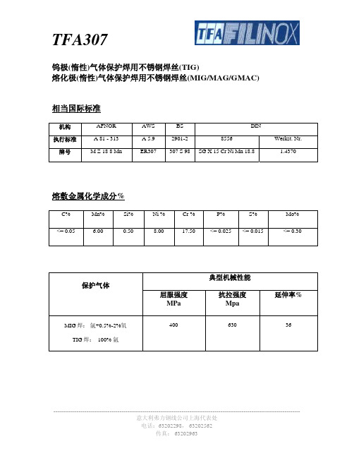
钨极(惰性)气体保护焊用不锈钢焊丝(TIG)特性与用途
电话:63202298, 63202562 传真: 63202963
Werkst. Nr. 1.4370
熔敷金属化学成分%
C%
Mn%
Si%
<= 0.05
6.00
0.50
Ni % 8.00
Cr % 17.50
P%
S%
<= 0.025 <= 0.015
Mo% <= 0.30
保护气体
MIG 焊: 氩+0.5%-2%氧 TIG 焊: 100% 氩
屈服强度 MPa
400
典型机械性能 抗拉强度 Mpa
TFA307
熔化极(惰性)气体保护焊用不锈钢焊丝(MIG/MAG/GMAC)特性与用途
742、MPS系列焊机与DC-400焊机性能比较
熊谷MPS -500与林肯DC-400焊机性能对比1.主要技术参数、性能、结构对比:焊机型号MPS-500DC-400 额定输出电流/电压 500A/39V 450A/38V 额定负载持续率 60% 60% 电气参数 电流调节范围 50A -500A60A -500A 外形尺寸 460mm×350mm×600mm698mm×566mm×840mm重量48Kg215 Kg功能转换单开关转换:同时转换动、静态特性,操作简便。
双开关转换:大电流开关切换电抗器抽头和动、静态特性,小开关切换电弧控制(通过饱和电抗器控制电弧)。
手柄机顶有可自动回位双手柄,手握处是软橡胶,手感舒适,可用手抬,人工移动方便。
顶部单吊环,人工移动困难。
冷却风道 独立风道(熊谷专利)设计,散热风道与控制电路、IGBT、整流器件完全隔离,更适合沙漠、潮湿、高温的工作环境。
风力集中,散热效果良好。
散风道控制板数量 1块2块 电磁兼容性措施 有,符合IEC 60974-10标准要求无 电流、电压表 数字表,可精确预设/显示电流、电压,便于远距离观察。
指针表 整 机结构外壳防护等级IP23IP232.节能分析:2.1逆变MPS-500焊机: 年耗电量=(19.5kW ×4.8小时+0.05 kW ×3.2小时)×245天=93.76×245天=22971.2(度,千瓦/小时)逆变NB-500焊机年用电费:0.79元×22971.2度=18147.25元 2.2晶闸管DC-400焊机: 年耗电量=(27.1kW ×4.8小时+0.3 kW ×3.2小时)×245天=131.04×245天=32104.8(度,千瓦/小时)晶闸管MIG/MAG 焊机年用电费:0.79元×32104.8度=25362.79元2.3使用逆变MPS-500焊机每年可节电9133.6度,节约电费7215.54元。
武汉力源信息技术 PS 系列 小型直焊式开关电源 选购指南
PS系列小型直焊式开关电源选购指南武汉力源信息技术有限公司目录产品选购树----------------------------------------------------2 PSI单输出隔离型DC-DC电源------------------------------------3 PSI双输出隔离型DC-DC电源------------------------------------5 PSH单输出高隔离度DC-DC电源----------------------------------8 PSH双输出高隔离度DC-DC电源----------------------------------9 PSW宽输入单输出隔离型DC-DC电源------------------------------11 PSW宽输入双输出隔离型DC-DC电源------------------------------13 PS系列超小型隔离AC-DC开关电源-----------------------15 PS系列外置式AC-DC适配器开关电源------------------------19 PSE系列超小型高压EL灯驱动电源-----------------------21 PSL系列非隔离DC-DC变换电源----------------------------------23 PSC200SRP高效率降压型DC-DC变换电源--------------------------25 PSC210SRP高效率降压型DC-DC变换电源--------------------------28 PSP100SRP宽输入电压范围降压型DC-DC电源----------------------31 PSP200SRP宽输入电压范围降压型DC-DC电源----------------------33 附录:产品尺寸图----------------------------------------------36 附录2:客户定制电源规格书-------------------------------------48产品选购树PSI单输出隔离型DC-DC电源产品说明PSI系列单输出隔离型DC-DC电源可将5V、12V、24V、48V工业标准电压隔离变换成所需的直流电压输出;可用于为需与主电路隔离的电路供电,从而达到排除系统间干扰或保护设备的目的。
悬点焊机备件清单_
天津七所高科技有限公司
2007年5月
序号
名称
型号
生产厂家
1
主板
LKN-F-QR(常规)
LKN-F-QR2(带集中控制)
天津七所高科技有限公司
2
可控硅
MTC500A/1200V
锦州双河/锦州777厂
3
变压器(控制器中)
TR2
天津通广集团
4
得力西空开
CDM1-225L/33102
得力西集团
欧罗特
三位开关
Ф22左开右闭EB6-BD3+105
欧罗特
二位开关
Ф22单常开EB6-BD2+101
欧罗特
急停开关
Ф22单常开EB6-BS54+101
ቤተ መጻሕፍቲ ባይዱ欧罗特
8
车型转换装置
四位转换开关
LW8A-10
上海二工
方灯
红EB6-AD22FR23
绿EB6-AD22FG23
黄EB6-AD22FY23
兰EB6-AD22FB23
5
指示灯(控制器上)
指示灯
Ф22绿色EB6-AD22G23
欧罗特
指示灯
Ф22黄色EB6-AD22Y23
欧罗特
指示灯
Ф22红色EB6-AD22R23
欧罗特
6
按钮
按钮(自复位)
Ф22红色单常开EB6-BA4
欧罗特
带灯按钮(自复位)
Ф22红色EB6-BW34
欧罗特
7
转换开关
二位开关
Ф22单常闭EB6-BD2+102
上海二工
9
电磁阀
SY9120-5DZ-03
高速焊薄板王:上海广为NB-270S逆变气保焊机
- ,
…) 组焊接 规 范; ☆良好 的 引弧性 能起 弧 ,冷引弧 成功率 高 ;☆双脉冲功 能可 获得与TI G悍
媲! 毛的鱼鳞纹 焊缝 ;☆标配机 器人和 专机通讯接 口;☆可扩 展联 网群控功 能,实现焊接过程
的智能化管理 ;☆可设定焊接 电流上 下限 ,防止超规 范的焊接 作业 ;☆完善 的保护功能 :具
有短路 保护 、过热保 护 、电 网异 常保护 可通 过数 显报 警 号识 别报 警原 因,并能记 录报警
履历 ;☆可选配数 字可调 焊枪 ,远程设 定调 节焊接 电流和 电压 ;☆碳铜模式 下,具 有根焊功
能 ,可 扩展 深 透 弧 功 能 、
高速焊 薄板王 :上海广 为NB 一 2 7 0 S 逆变气保焊机
广为告诉你 : 上海广 为N B 一 2 7 0 S 气保 焊机 ,称之为薄板王 ,最 薄可焊 0 . 5 m m。
工厂老板 问 .各种原材料涨价严重 ,抽头式焊机 比去年贵 了好多 ,有没 有哪家焊机 既能 满足抽头 的焊接工 艺 ,成 本又不那么高 的?
一 曩 禹 雷 精 一 ■
广 为告诉你 :上海 广为N B 一 2 7 0 S 气保焊机 ,可替代抽头式焊机 ,还 省 电3 0 %。
H y p e r t h e r m海宝新一代高端等离子系 ̄ / t . XP R 3 0 0 隆重上市
0口∞ 。 = £ , £ j o‘ 凫 』 0 0
X P R 3 0 0 系统开始 于穷极详 尽的研 究 ,得益于 合作伙伴 和最终 用户的建议 ,发展于 工程 师的大胆创 想和数万 小时 的验 证测试 ,X P R 3 0 0 现在可 以用等离子 前所未有 的方式来服 务金
寓 溯
- 1、下载文档前请自行甄别文档内容的完整性,平台不提供额外的编辑、内容补充、找答案等附加服务。
- 2、"仅部分预览"的文档,不可在线预览部分如存在完整性等问题,可反馈申请退款(可完整预览的文档不适用该条件!)。
- 3、如文档侵犯您的权益,请联系客服反馈,我们会尽快为您处理(人工客服工作时间:9:00-18:30)。
B/E Aerospace, Inc. Specification Nbr: Title: Revision: Issue Date:
Seating Products Group SPG-MPS-027 Resistance Spot Welding of Aluminum Rev. A January 8, 2003
Manufacturing Process Specification
This document is to be referenced on engineering drawings. It defines functional/performance requirements, manufacturing process methods and levels of quality of the components being Seating Products Group
Page 1 of 34
Last printed: May 18, 2005
B/E Aerospace, Inc. Specification Nbr: Title: Revision: Issue Date:
Seating Products Group SPG-MPS-027 Resistance Spot Welding of Aluminum Rev. A January 8, 2003
Date:
Approved by:
Tommy Plant - VP Engineering
Date:
Approved by:
Sami Kazi – Manager Certification Engineering
Date:
Approved by:
Tom McQuaid – VP Quality Assurance: Kilkeel
1455 Fairchild Road Winston-Salem, NC 27105 USA 2 Moor Road, Kilkeel County Down, Northern Ireland BT34 4NG
Manufacturing Process Specification No: Title: Revision: Issue Date:
B/E Aerospace, Inc. Specification Nbr: Title: Revision: Issue Date:ห้องสมุดไป่ตู้
1. Revision History
Rev. Level A Initial Release Approval: Certification Engineer Sami Kazi
Description
Author Steve Bell
Date
01-08-03
Page 2 of 34
Last printed: May 18, 2005
1. Revision History..............................................................................................................2 2. General Information........................................................................................................9 2.1 Introduction .............................................................................................................9 2.1.1 B/E Identification ..........................................................................................9 2.2 Scope of Specification ............................................................................................9 2.3 Reference Documents............................................................................................9 2.3.1 ASTM Publications.......................................................................................9 2.3.2 AWS Publications.........................................................................................9 2.3.3 SAE Publications..........................................................................................9 2.3.4 U.S. Government Publications...................................................................10 2.3.5 Legacy B/E Documents..............................................................................10 2.4 Definitions .............................................................................................................10 2.4.1 Acronyms: ..................................................................................................10 2.4.2 Arc Strike....................................................................................................10 2.4.3 Classifications ............................................................................................10 2.4.3.1 Class A: Primary Structure or Critical Applications ....................10 2.4.3.2 Class B: Secondary Structure or Semi-Critical Applications ......10 2.4.3.3 Class C: Non-structural and Non-critical Application .................11 2.4.4 Close Space Welds....................................................................................11 2.4.5 Cognizant Engineering Organization .........................................................11 2.4.6 Contractor / Supplier / Vendor....................................................................11 2.4.7 Faying Surface ...........................................................................................11 2.4.8 Finished Weld ............................................................................................11 2.4.9 Foil Thickness ............................................................................................11 2.4.10 Member ......................................................................................................11 Page 3 of 34 Last printed: May 18, 2005
SPG-MPS-027 Resistance Spot Welding of Aluminum Rev. A January 8, 2003
Authored by:
Steven R. Bell – Manager Process Engineering
Date:
Approved by:
Victor Clark - Manager Quality Assurance
Date:
Approved by: