欧姆龙时间继电器h3de
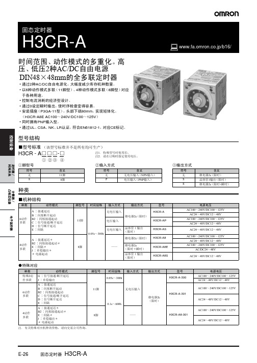
OMRON时间继电器 H3CR-A
③输出方式
符号 无 S E 含义 继电器2c (限时) 晶体管1输出 (限时) 继电器2c (限时+瞬时)
种类
■机种结构
种类 动作模式 A ∶接通延迟 B ∶闪烁断开起动 B2 ∶闪烁接通起动 C ∶信号接通/断开延迟 D ∶信号断开延迟 E ∶间隔 A ∶接通延迟* B2 ∶闪烁接通起动* E ∶间隔* J ∶单稳输出* * 电源起动 脚型号 时间规格 输入方式 无电压输入 继电器2c (限时) 11脚 电压输入 无电压输入 0.05s~300h 晶体管1输出 (限时) 继电器2c (限时) 8脚 —— 继电器2c (限时+瞬时) 晶体管1输出 (限时) H3CR-AP H3CR-AS H3CR-A8 H3CR-A8E H3CR-A8S 输出方式 型号 H3CR-A 电源电压 AC100~240V/DC100~125V AC24~48V/DC12~48V AC100~240V/DC100~125V AC24~48V/DC12~48V AC24~48V/DC12~48V AC100~240V/DC100~125V AC24~48V/DC12~48V AC100~240V/DC100~125V AC/DC24~48V AC24~48V/DC12~48V
(DC24V时) 输出ON时∶0.3W 输出OFF时∶0.2W
复位电压
控制输出
接点输出 : AC250V/DC30V 5A DC125V 0.15A 阻性负载 (cosφ=1)
接点输出 : AC250V/DC30V 5A DC125V 0.15A 阻性负载 (cosφ=1)
适用温度范围 保存温度范围 使用环境湿度
*1. DC规格的波纹率在20%以下。 (可以使用范围至单相全波整流电源) *2. AC24~48V/DC12~48V规格有浪涌电流,因此采用传感器等无接点输出开关定时器本体电源时必须注意。 (备有浪涌电流为50mA左右的DC24V专用品作为特殊品。 H3CR-A-302型、 H3CR-A8-302型) *3. ②-⑦端子短路、⑩-⑥端子短路状态 (包括输入电路的消耗电流在内)时的值。
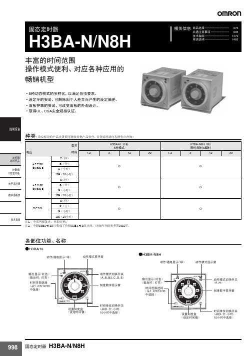
欧姆龙时间继电器h3ba_n_n8h
ᯊ䯈ऩԡߛᤶᓔ݇ ˄Ң金ǃߚǃᇣᯊǃ
10ᇣᯊЁ䗝ᢽ˅
998 固态定时器 H3BA-N/N8H
额定值/性能
动作电压范围 电源恢复
项目
消耗电力
接点容量
无电压输入
动作时间精度 设定误差 电压影响 温度影响 绝缘阻抗
输出控制
耐电压
脉冲阻抗
耐噪声 抗静电 振动
冲击 周围温度 周围湿度
寿命
保护构造 重量
ᡔᴃᣛफ
78 63.7
13.6
ᅝ㺙⦃ 䴶ᵓⲪ
䴶ᵓ 3*ൟ 㚠䴶䖲ᦦᑻ˄ଂ˅
䴶ᵓ
䴶ᵓ㺕ߛ
1004 固态定时器 H3BA-N/N8H
●Y92F-71安装时的尺寸
䴶ᵓ
P3GA-11ൟ 㚠䴶䖲ᦦᑻ
H3BA-N
H3BA-N8H
112.2
109.9
101.3
99
P2CF-11ൟ 注. 安装尺寸因DIN导轨而不同。
耐久 误动作 耐久 误动作
机械 电气
H3BA-N
H3BA-N8H
85%~110%额定电压
最低动力起动时间:0.1s
110VAC约4.6VA(1.5W)
110VAC约3.6VA(1.6W)
220VAC约7.9VA(1.3W)
220VAC约5.4VA(1.4W)
24VDC约0.6W
24VDC约0.9W
接点输出:5A在250VAC,阻性负载cosφ =1
tˉa
tˉa tˉa
t
t
t
ᡔᴃᣛफ
t ⬉⑤ĸ-ŀ
䍋ࡼĸ-ļ
ԡĸ-Ľ
ķ-ĺ 䰤ᯊ⚍gNC (ŀ11-ľ)
ķ-Ĺ 䰤ᯊ⚍gNO(ŀ11-Ŀ)
欧姆龙 AQV410 光电式继电器(GU-E 型) 安装、使用说明书
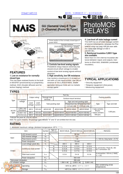
125VDE123654GU (General Use)-E Type[1-Channel (Form B) Type]mm inch8.8±0.05.346±.0026.4±0.05.252±.0023.6±0.2.142±.0088.8±0.05.346±.0026.4±0.05.252±.0023.9±0.2.154±.008 FEATURES1. Low on resistance for normally-closed typeThis has been realized thanks to the built-in MOSFET processed by our proprietary method, DSD (Double-diffused and Se-lective Doping) method.Source electrode Gate electrodePassivation membraneCross section of the normally-closed type of power MOSIntermediate insulating membraneGateoxidation membraneDrain electrode2. Controls low-level analog signals PhotoMOS relays feature extremely low closed-circuit offset voltage to enable control of low-level analog signals without distortion.3. High sensitivity, low ON resistance Can control a maximum 0.13 A load cur-rent with a 5 mA input current. Low ON re-sistance of 18 Ω (AQV410EH). Stable operation because there are no metallic contact parts.4. Low-level off state leakage current The SSR has an off state leakage current of several milliamperes, whereas the Pho-toMOS relay has only 100 pA even with the rated load voltage of 400 V (AQV414E).5. Reinforced insulation 5,000 V type also available.More than 0.4 mm internal insulation dis-tance between inputs and outputs. Con-forms to EN41003, EN60950 (reinforced insulation).TYPICAL APPLICATIONS• Security equipment• T elepone equipment (Dial pulse)• Measuring equipmentTYPES*Indicate the peak AC and DC values.Note: For space reasons, the package type indicator "X" and "Z" are omitted from the seal.TypeI/O isolation voltageOutput rating*Part No.Packing quantityThrough hole terminalSurface-mount terminalLoad voltage Load current Tube packing style T ape and reel packing style T ube T ape and reelPicked from the 1/2/3-pin side Picked from the 4/5/6-pin side AC/DC type 1,500 V AC(Standard)400 V 120 mA AQV414E AQV414EA AQV414EAX AQV414EAZ 1 tube contains50 pcs.1 batch contains500 pcs.1,000 pcs.5,000 V AC(Reinforced)350 V 130 mA AQV410EH AQV410EHA AQV410EHAX AQV410EHAZ 400 V120 mAAQV414EHAQV414EHAAQV414EHAXAQV414EHAZRATING1. Absolute maximum ratings (Ambient temperature: 25 ° C 77 ° F )ItemSymbol Type of connectionAQV414E(A)AQV410EH(A)AQV414EH(A)RemarksInputLED forward current I F 50 mA LED reverse voltage V R 3 V Peak forwrd current I FP 1 A f = 100 Hz, Duty factor = 0.1%Power dissipationP in 75 mW OutputLoad voltage (peak AC)V L 400 V 350 V 400 V Continuous load currentI LA 0.12 A 0.13 A 0.12 A A connection: Peak AC, DC B,C connection: DCB 0.13 A 0.15 A 0.13 AC 0.15 A 0.17 A 0.15 A Peak load currentI peak 0.3 A0.4 A 0.3 AA connection: 100 ms (1 shot), V L = DCPower dissipationP out 500 mW Total power dissipation P T 550 mW I/O isolation voltage V iso 1,500 V AC 5,000 V AC5,000 V ACTemperature limitsOperating Topr –40 ° C to +85 ° C –40 ° F to +185 ° F Non-condensing at low temperaturesStorageTstg –40 ° C to +100 ° C –40 ° F to +212 °FPhotoMOS RELAYS查询AQV410供应商AQV414E, AQV41 r EH1262. Electrical characteristics (Ambient temperature: 25 ° C 77 ° F )For type of connection, see Page 32.Note:Recommendable LED forward currentStandard type I F = 5 mAReinforced type I F = 5 to 10 mA *Operate/Reverse timeItemSymbol T ype ofconnec-tion AQV414E(A)AQV410EH(A)AQV414EH(A)Condition InputLED operate (OFF) currentTypical I Foff — 1.45 mA1.9 mA 1.75 mA I L = Max.Maximum 3.0 mALED reverse (ON) current Minimum I Fon —0.3 mA 0.4 mA 0.3 mA I L = Max.Typical 1.40 mA 1.8 mA 1.70 mALED dropout voltageTypical V F — 1.14 V (1.25 V at I F = 50 mA)I F = 5 mAMaximum 1.5 VOutputOn resistanceTypical RonA26 Ω 18 Ω 25.2 Ω I F = 0 mA IL = Max.Within 1 s on time Maximum 50 Ω 35 Ω 50 Ω TypicalRonB20 Ω 13 Ω 19 Ω I F = 0 mA IL = Max.Within 1 s on time Maximum25 Ω 17.5 Ω 25 Ω Typical Ron C 10 Ω 6.5 Ω 10 Ω I F = 0 mA IL = Max.Within 1 s on time Maximum12.5 Ω 8.8 Ω 12.5 Ω Off state leakage currentMaximum ILeak — 1 µ A 10 µ A 10 µ A I F = 5 mA V L = Max.T ransfercharacteristicsSwitching speedOperate (OFF) time*Typical T off —0.7 ms 1.5 ms 1.3 ms IF = 0 mA ¨ 5 mA I L = Max.Maximum 2.0 ms 3.0 ms 3.0 ms Reverse (ON) time*Typical T on —0.1 ms 0.3 ms 0.3 ms IF = 5 mA ¨ 0 mA I L = Max.Maximum 1.0 ms 1.5 ms 1.5 ms I/O capacitance Typical C iso —0.8 pF0.8 pF 0.8 pFf = 1 MHz V B = 0Maximum 1.5 pF Initial I/O isolation resistanceMinimumRiso—1,000 M Ω500 V DCs For Dimensions, see Page 27.s For Schematic and Wiring Diagrams, see Page 32. s For Cautions for Use, see Page 36.REFERENCE DATA1. Load current vs. ambient temperature char-acteristicsAllowable ambient temperature:–40 ° C to +85 ° C–40 ° F to +185 ° FType of connection: A2. On resistance vs. ambient temperature char-acteristicsMeasured portion: between terminals 4 and 6;LED current: 0 mA; Load voltage: Max. (DC);Continuous load current: Max. (DC)3. Operate (OFF) time vs. ambient temperature characteristicsLED current: 5mA; Load voltage: Max. (DC);Continuous load current: Max. (DC)Ambient temperature, °CL o a d c u r r e n t , m A Ambient temperature, °CO n r e s i s t a n c e , Ω1020304050Ambient temperature, °CO p e r a t e (O F F ) t i m e , m s02.03.05.01.04.0AQV414E, AQV41 r EH4. Reverse (ON) time vs. ambient temperature characteristicsLED current: 5 mA; Load voltage: Max. (DC);Continuous load current: Max. (DC)5. LED operate (OFF) current vs. ambient tem-perature characteristicsLoad voltage: Max. (DC);Continuous load current: Max. (DC)6. LED reverse (ON) current vs. ambient tem-perature characteristicsLoad voltage: Max. (DC);Continuous load current: Max. (DC)Ambient temperature, °CR e v e r s e (O N ) t i m e , m s0.80.60.40.2Ambient temperature, °CL E D o p e r a t e (O F F ) c u r r e m t , m A12345Ambient temperature, °CE D r e v e r s e (O N ) c u r r e n t , m A。
欧姆龙继电器型号 文档 (2)
公司是欧姆龙一级代理商,价格优势明显,质量有保证,有大量库存,供货期短。
欢迎新老客户来电查询联系人:1 3 5 2 0 1 1 5 8 9 1 传0 1 0- 8 0 1 1 5 5 5 5转7 5 9 7 1 13F88L-RS173G3IV-PLKEB45P53G3JV-MANUAL3G3JZ-AB0223G3MV-A4075(YES)3G3MZ-A2004-ZV23G3MZ-A2007-ZV23G3MZ-A2015-ZV23G3MZ-A2055-ZV23G3RV-B418K-ZV13G3RV-B422K-ZV13G3RV-B4900-ZV13G3RX-A4220-Z43767-0010 MC374005-3066 UM5-3066C200H-ATT01C200H-BC101-V2C200H-CP114C200H-DA001C200H-DA002C200H-ID218C200H-ID501C200H-NC111C200H-OD501C200H-TS001C200HW-COM01C200HW-COM05-EV1C200HW-DRM21-V1C200HW-NC213C500-CE405CJ1W-OD263CP1W-20EDT1(Q)CP1W-40EDT1CPM1A-20EDT1CPM1A-40CDT-A-V1 CPM2A-20CDR-DCPM2A-20CDT-DCPM2A-30CDR-DCQM1-ID211CQM1-ME04RCQM1H-PLB21CRT1-AD04CS1D-CPU44SCS1H-CPU66HCS1H-CPU67HCS1W-BAT01CS1W-BI033CS1W-CN224CS1W-OC201CS1W-PDC55CS1W-SCU31-V1D4N-212GDRT1-232C2DRT2-AD04E2E-X10D1S DC12-24 2ME3X-DAC21-S 2ME5AZ-C3E5AZ-Q3E5AZ-R3E5CN-Q2HBT AC100-240 (Q)E5CN-R2HBT AC100-240 (Q)E5CN-R2T AC100-240 (Q)E5CZ-Q2 AC100-240E5CZ-R2MT AC100-240E5EZ-C3E6C2-CWZ6C 1024P/R 2M BY OMSG3JA-C425B AC100-240 FOR CHINA G3JA-C430B AC100-240 FOR CHINA G3JA-C437B AC100-240 FOR CHINA G3JA-D420B AC100-240 FOR CHINA G3JA-D425B AC100-240 FOR CHINA G3JA-D432B AC100-240 FOR CHINA G3JA-D451B AC100-240 FOR CHINA G3PB-535B-2N-VD DC12-24H5CN-XCN AC100-240H5F-BMKS2P DC12MKS3P-5 DC48MPT-CN550NS10-TV01B-V2R7A-CNB01S-ZR7A-CNB01SB-ZR7A-CNZ01C-ZR7D-AP04HR7D-AP08HR7D-BP01H-ZR7D-BP02H-ZR7D-BP02HH-ZR7D-BP04H-ZR7D-ZP01HR7D-ZP02HR7M-A40030-S1R7M-A75030-S1R7M-Z10030-S1ZR7M-Z20030-S1ZR88A-CNG01SB-ZR88D-GN01H-ML2-ZR88D-GN02H-ML2-ZR88D-GN04H-ML2-ZR88D-GN08H-ML2-ZR88D-GN10H-ML2-ZR88D-GN15H-ML2-ZR88D-GN20H-ML2-ZR88D-GN50H-ML2-ZR88D-GN75H-ML2-ZR88D-GT50H-ZR88D-GT75H-ZR88D-WN08H-ML2R88D-WN10H-ML2R88M-G10030H-BS2-Z R88M-G10030H-ZR88M-G1K020H-S2-Z R88M-G1K020H-ZR88M-G1K020T-BS2-Z R88M-G1K020T-S2-Z R88M-G1K020T-ZR88M-G1K030H-BS2-Z R88M-G1K030H-S2-Z R88M-G1K030H-ZR88M-G1K030T-S2-Z R88M-G1K520H-BS2-Z R88M-G1K520H-S2-Z R88M-G1K520H-ZR88M-G1K520T-BS2-Z R88M-G1K520T-S2-Z R88M-G1K520T-ZR88M-G1K530H-S2-Z R88M-G1K530T-S2-Z R88M-G20030H-BS2-Z R88M-G20030T-BS2-Z R88M-G20030T-S2-Z R88M-G2K010H-S2-Z R88M-G2K010H-ZR88M-G2K010T-S2-Z R88M-G2K010T-ZR88M-G2K020H-BS2-Z R88M-G2K020H-S2-Z R88M-G2K020H-ZR88M-G2K020T-S2-ZR88M-G2K030H-S2-Z R88M-G2K030T-S2-Z R88M-G3K010H-BS2-Z R88M-G3K010H-S2-Z R88M-G3K010H-ZR88M-G3K010T-S2-Z R88M-G3K020H-BS2-Z R88M-G3K020H-S2-Z R88M-G3K020H-ZR88M-G3K020T-S2-Z R88M-G3K020T-ZR88M-G3K030H-BS2-Z R88M-G3K030H-S2-Z R88M-G3K030H-ZR88M-G40030H-B-ZR88M-G40030H-BS2-Z R88M-G40030H-ZR88M-G40030T-BS2-Z R88M-G40030T-S2-Z R88M-G4K020H-BS2-Z R88M-G4K020H-S2-Z R88M-G4K020T-S2-Z R88M-G4K030H-BS2-Z R88M-G4K030H-S2-Z R88M-G4K510H-BS2-Z R88M-G4K510H-S2-Z R88M-G4K510T-S2-Z R88M-G5K020H-BS2-ZR88M-G5K030H-BS2-ZR88M-G5K030H-S2-ZR88M-G6K010H-BS2-ZR88M-G6K010H-S2-ZR88M-G75030H-BS2-ZR88M-G75030T-BS2-ZR88M-G75030T-S2-ZR88M-G7K515H-BS2-ZR88M-G7K515H-S2-ZR88M-G7K515T-S2-ZR88M-G90010T-S2-ZR88M-GP10030H-ZR88M-GP40030H-ZR88M-W10030T-S1SH-001-01MSH-001-03MSH-001-05MSH-001-10MV400-W23 3MV400-W24 3MWLCA32-41ZR-RX20A-CHROZR-RX40A-CHROZR-XRB1ZR-XRE1我公司是欧姆龙一级代理商,价格优势明显,质量有保证,有大量库存,供货期短。
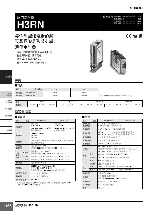
欧姆龙时间继电器h3rn
ࠊ䆒
˄ⷁ䏃⬉⌕˅
⬉⌕
L
ᅮᯊ఼/ ᅮᯊᓔ݇
·代替G2R继电器,讨论使用H3RN时,请确认额定电源电压、控 制输出在H3RN的额定范围内,然后再使用。
䅵఼᭄/ ߌ䕂ᅮԡ఼
⬉ᄤ⏽఼
᭄ᄫ䴶ᵓ㸼
●关于配线
·H3RN的操作电源电路和控制输出之间要确保基础绝缘。 基础绝缘:过电压等级III 污染度2 (AC240V时的绝缘距离要求值为 表面3.0mm、空间3.0mm)
H3RN-2/-21
ᅮᯊ఼⬉䏃
䚼䕧ܹ
各部分名称及功能
⬉⑤˄3-8˅
䚼ⷁ䏃˄1-4˅
䚼䕧ܹ˄1-3˅ 䰤ᯊ⚍ NO˄6-5˅
⬉⑤ࡴᰒ冫˄PW˅ ࡼЁᰒ冫˄OUT˅
Rt
Rt
t
t
t
50ms ҹϞ
注. t表示设置时间,Rt表示复位时间
ᅮᯊ఼⬉䏃
(DIN显示)
ᅮᯊ఼/ ᅮᯊᓔ݇
䅵఼᭄/ ߌ䕂ᅮԡ఼
±2%以下(最大刻度时间下)
温度的影响
±2%以下(最大刻度时间下)
绝缘电阻
100MΩ以上(DC500V兆欧表)
耐电压
AC2,000V 50/60Hz 1min (操作电源电路和控制输出之间以及异极接点之间) AC1,000V 50/60Hz 1min(非连续接点之间)
振动
耐久 误动作
10~55Hz 单振幅0.75mm 3方向 各1h 10~55Hz 单振幅0.5mm 3方向 各10min
·脉冲动作和间隔动作的电源连接端子编 号不同,请充分注意。
·使用脉冲动作时的电源连接为端子编号
③:- -⑧:+ 。 另外, 插座上④-①外部短路。 外部输入端子为③-①。 ·使用间隔动作时的电源连接为①:- - ⑧:+ 。
OMRON欧姆龙-H3Y-2_4-时间继电器
OMRON欧姆龙-H3Y-2/4-时间继电器
接近开关是一种无需与运动部件进行机械直接接触而可以操作的位置开关,当物体接近开关的感应面到动作距离时,不需要机械接触及施加任何压力即可使开关动作,从而驱动直流电器或给计算机(plc)装置提供控制指令。
接近开关是种开关型传感器(即无触点开关),它既有行程开关、微动开关的特性,同时具有传感性能,且动作可靠,性能稳定,频率响应快,应用寿命长,抗干扰能力强等、并具有防水、防震、耐腐蚀等特点。
产品有电感式、电容式、霍尔式、交、直流型。
接近开关又称无触点接近开关,是理想的电子开关量传感器。
当金属检测体接近开关的感应区域,开关就能无接触,无压力、无火花、迅速发出电气指令,准确反应出运动机构的位置和行程,即使用于一般的行程控制,其定位精度、操作频率、使用寿命、安装调整的方便性和对恶劣环境的适用能力,是一般机械式行程开关所不能相比的。
它广泛地应用于机床、冶金、化工、轻纺和印刷等行业。
在自动控制系统中可作为限位、计数、定位控制和自动保护环节等。
OMRON欧姆龙-H3Y-2/4-时间继电器。
H3DE选型样本

Solid-state Timer H3DE DIN Track Mounted, Standard 22.5-mm Width Timer RangeA wide AC/DC power supply range (24 to 230 VAC/DC) reduces the number of timer models kept in stock.(except for H3DE-H)12-VDC model available for a specific application. (H3DE-M2)Nameplate provided for easy timer identification and management.Terminal clamp left open when delivered.Finger protection terminal block to meet VDE0106/P100.Enables easy sequence checks through instantaneous outputs for a zero set value at any time range.Incorporates environment-friendly, cadmium-free contacts. (except for H3DE-H)High immunity to inverter noise.Approved by UL and CSA.Conforms to EN61812-1 and IEC60664-1 (VDE0110) 4 kV/2 for Low Voltage and EMC Directives.H3DEStandard TimerH3DE-MH3DE-STwin TimerH3DE-FStar-delta TimerH3DE-GPower OFF-delay TimerH3DE-H H3DE-M/S H3DE-F H3DE-G H3DE-HContentsSolid-state TimerH3DE-M/S5. . . . . . . . . . . . . . . . . . . . . . . . . . . . . . . . . . . . . . . . . . . . . . . . . . . . . . . . . .H3DE-F14. . . . . . . . . . . . . . . . . . . . . . . . . . . . . . . . . . . . . . . . . . . . . . . . . . . . . . . . . . . .H3DE-G20. . . . . . . . . . . . . . . . . . . . . . . . . . . . . . . . . . . . . . . . . . . . . . . . . . . . . . . . . . . .H3DE-H26. . . . . . . . . . . . . . . . . . . . . . . . . . . . . . . . . . . . . . . . . . . . . . . . . . . . . . . . . . . .Common to ALL TimersAccessories32. . . . . . . . . . . . . . . . . . . . . . . . . . . . . . . . . . . . . . . . . . . . . . . . . . . . . . . .Precautions33. . . . . . . . . . . . . . . . . . . . . . . . . . . . . . . . . . . . . . . . . . . . . . . . . . . . . . . . .Solid-state Multi-functional Timer H3DE-M/-S Eight operating modes (H3DE-M) and fouroperating modes (H3DE-S) cover a wide range ofapplications.Programmable contact enables the building of aself-holding relay circuit (-j2 models).A wide time setting range of 0.10 s to 120 h.Note:Can be mounted to 35-mm DIN track with a plate thickness of 1 to 2.5 mm.Note:When the main dial is set to “0” for all settings, the output will operate instantaneously.RatingsNote: 1.DC ripple rate: 20% max.2.Since an inrush current of 0.25 A will occur when using the power supply voltage at 24 VDC, pay careful attention when turning on oroff the power supply to the T imer with a solid-state output such as a sensor.3.The power consumption is for mode A after the T imer counts the time-up time and for the AC input at 50 Hz. The power consumptionof the H3DE-M j includes the input circuit with the B1 and A1 terminals short-circuited.CharacteristicsNote: 1.With the H3DE-M j, if the voltage exceeds 26.4 V AC/DC, the following hold at signal OFF for C, D, and G modes: Accuracy of operating time: ±1% ±50 ms max. at 1.2-s rangeSetting error: ±10% +100/–50 ms max.Signal input time: 100 ms min.2.For reference : A maximum current of 0.15 A can be switched at 125 VDC (cosφ=1).A maximum current of 0.1 A can be switched if L/R is 7 ms.In both cases, a life of 100,000 operations can be expected.The minimum applicable load is 10 mA at 5 VDC (failure level: P).Output type selector switch for H3DE-M2/-S2 (default setting is time-limit output)Setting Output typeTime-limit output (terminal numbers 25, 26 and28) (default setting)Instantaneous output(terminal numbers 21, 22 and 24)Output Type Selector Switch Settings(Bottom View)H3DE-S1/-S2I/O FunctionsNote:When the output type selector switch on the bottom of the T imer is set to the instantaneous side, the relay R2 (terminal numbers 21/25,22/26, and 24/28) becomes an instantaneous contact and turns ON/OFF in synchronization with the changes in the power supply .Setting of SelectorThe selectors can be turned clockwise and counterclockwise to se -lect the desired time unit, time scale, or operating mode.Each selector has a snap mechanism that secures the selector at a given position. Set the selector at a position at which it is secured.Do not set it midway between two securing positions or a malfunc -tion could result from improper setting.Operating mode selectorOperating mode display windowSelection of Operating ModeThe H3DE-M/-S can be set to any one of the operating modes A to J.Turn the operating mode selector with a screwdriver until the de-sired operating mode (A, B, C, B2, D, E, J, or G for the H3DE-M and A, E, J, or B2for the H3DE-S) appears in the operating mode display window located below the selector .Selection of T ime Unit and T ime ScaleThe desired time unit (s, m, h, or 10h) can be displayed in the time unit display window above the time setting dial by turning the time unit selector located at the upper right corner of the front panel. T ime scale (0.1 or 1) is selected with the time scale selector at the upper left corner of the front panel, it appears in the time scale display win -dow above the selector .T ime unit selectorNote: 1.The minimum power reset time is 0.1 s and the minimum signal input time is 0.05 s.2.The letter “t” in the timing charts stands for the set time and “t–a” means that the period is less than the time set.tFor power-on operation, impose voltage to theStart input. The Timer starts operating at themoment the power is turned on.Start input is invalid while the Timer is in opera-tion.**Basic operationt t t tFor power-on operation, impose voltage to theStart input. The Timer starts operating at themoment the power is turned on.Start input is invalid while the Timer is in opera-tion.**Basic operationOutputt t t tFor power-on operation, impose voltage to theStart input. The Timer starts operating at themoment the power is turned on.Start input is invalid while the Timer is in opera-tion.**Basic operationOutputtt t tStart input is invalid while the Timer is in opera-tion.*Note:The start input of the H3DE-M1 or H3DE-M2 model is activated by applying a voltage to B1 and A2 terminals.The voltage can be applied by turning on the contact between B1 and A1 (Refer to T erminal Arrangement).tStart input is valid and re-triggerable while theTimer is in operation.*tBasic operationFor power-on operation, impose voltage to theStart input. The Timer starts operating at themoment the power is turned on.Start input is valid and re-triggerable while theTimer is in operation.**Basic operationt t t t*t t tt–a t–aApprox. 1±0.6 s (fixed)Approx.1±0.6 s(fixed) Approx.1±0.6 s(fixed)Note:The start input of the H3DE-M1 or H3DE-M2 model is activated by applying a voltage to B1 and A2 terminals.The voltage can be applied by turning on the contact between B1 and A1 (Refer to T erminal Arrangement).H3DE-M/-STerminal block (black)Surface color:Light gray 5Y7/1 (OMRON)Output type selector switch (default setting: Time-limit output) 15R118161816A2B1A115(see note 2)(see note 2)(see note 2)(see note 2)------------------------------------------------------------------------------------------------------------------------------------------------------------------------------------------------------------------------------------------------------Note: 1.The relay R2 can be set to either instantaneous or time-limit contact using the switch located on the bottom of the T imer.2.DC supply voltage does not require the designation of polarity.3.The contact symbol for the H3DE is indicated withThe inputs of the H3DE-M1/-M2 are voltage (voltage imposition or open) inputs.No-contact Input(Connection to PNP output sensor .)Contact InputV oltage Input Signal LevelsNo-contact inputContact input1. T ransistor ONResidual voltage: 1 V max.(V oltage between terminals B 1 and A 2 must be more than the rated “H-level” voltage (20.4 VDC min.).)2. T ransistor OFFLeakage current: 0.01 mA max.(V oltage between terminals B 1 and A 2 must be less than the rated “L-level” voltage (2.4 VDC max.).)Use contacts that can adequately switch 0.1 mA at each voltage to be imposed. (When the contacts are ON orOFF , voltage between terminals B 1 and A 2 must be within the following ranges:When contacts are ON:20.4 to 253 V AC/DC When contacts are OFF:0 to 2.4 V AC/DCOperates with PNP transistor ONOperates with relay ONNo-contact Input(Connection to NPN output sensor .)SensorA 1B 1A 224 VDC (+)(–)Operates with NPN transistor ONTimerSolid-state Twin Timer H3DE-F Operates in flicker-OFF or flicker-ON start modewith one Unit.Independent ON- and OFF-time settings.Combinations of long ON- or OFF-time and shortOFF- or ON-time setting are possible.Long time range from 0.1 s to 12 h for both ON andOFF time settings.H3DE -11.F:Twin timersNote:Can be mounted to 35-mm DIN track with a plate thickness of 1 to 2.5 mm.Note: 1.T ime scale display is applied commonly for ON and OFF time.2.When the main dial is set to “0” for all settings, the output will operate instantaneously. RatingsNote:DC ripple rate: 20% max.CharacteristicsNote:For reference:A maximum current of 0.15 A can be switched at 125 VDC (cosφ=1).A maximum current of 0.1 A can be switched if L/R is 7 ms.In both cases, a life of 100,000 operations can be expected.The minimum applicable load is 10 mA at 5 VDC (failure level: P).Time scale display windowTime scale selector (select 0.1 or 1)Output ON indicator (orange)Output OFF indicator (green)Nameplate for user use (20 x 5.4 mm white panel)ON-time unit display windowTime unit selector(select one from s, 10s, min, or h for output ON)ON-time setting dial OFF-time setting dialOFF-time unit display windowON/OFF start selector(default is flicker-OFF start)OFF-time unit selector(select one from s, 10s, min, or h)Time Unit SelectionThe time unit display window for output ON is located on the upper-right side of the front panel above the corresponding time unit selec -tor.The time unit display window for output OFF is located on the lower-right side of the front panel belowthe corresponding time unit selec -tor.According to the setting of each time unit selector , “sec” for seconds,“10s” for 10 seconds, “min” for minutes, or “hrs” for hours will appear in the corresponding time unit display window .ON-time unit display window ON-time unit selector (select one from s, 10s, min, or h)OFF-time unit selector (select one from s, 10s, min, or h)OFF-time unit display windowTime Scale SelectionThe time scale selector on the upper-left side of the front panel can be set to 0.1 or 1 as a magnification coef ficient.Time scale display window Time scale selectorON-time setting dialOFF-time setting dialTime SettingUse the ON/OFF-time setting dial to set the ON/OFF time.t ON : ON set time t OFF : OFF set time0.1 s min.t ON : ON set time t OFF : OFF set time0.1 s min.Note: 1.The reset time requires a minimum of 0.1 s.2.When power is supplied in flicker-ON start mode, the OFF indicator lights momentarily . This, however , has no ef fect on the perfor -mance of the T imer.Terminal block (black)Surface color:Light gray 5Y7/1(OMRON)Terminal block (black)Note:DC supply voltage does not require the designation of polarity.Solid-state Star-delta Timer H3DE-G A wide star-time range (up to 120 seconds) andstar-delta transfer time range (up to 0.5 seconds)H3DE -11.G:Star-delta timerNote:Can be mounted to 35-mm DIN track with a plate thickness of 1 to 2.5 mm.RatingsNote:DC ripple rate: 20% max.CharacteristicsNote:For reference:A maximum current of 0.15 A can be switched at 125 VDC (cosφ=1).A maximum current of 0.1 A can be switched if L/R is 7 ms.In both cases, a life of 100,000 operations can be expected.The minimum applicable load is 10 mA at 5 VDC (failure level: P).Star operation indicator (green)Delta operation indicator (orange)Time setting dial (for setting star operation time)Star-delta transfer time selectorStar-delta transfer time display windowTime scale display window Star operation time scale selector (select 1 or 10)Nameplate for user use (20 x 5.4 mm white panel)(Front View)AC (DC) inputPower supply circuitStar operation indicator Delta operation indicatorIndicator circuitOutput circuitStar opera-tion time counting circuitStar-delta transfer timeselectionStar-delta transfer time oscilla-tion circuitStar-delta transfer time countingcircuitStar operationDelta operationStar opera-tion time oscillation circuit Staroperation time scale selectorTime Unit SettingThe star-delta transfer time is set to 0.05, 0.1, 0.25 or 0.5 with the star-delta transfer time selector on the lower-right side of the front panel and the set value appears in the star-delta transfer time dis -play window below the selector .Star-delta transfer time selectorStar-delta transfer time dis-play windowTime Scale SelectionThe star operation time scale selector on the upper-left side of the front panel can be set to 1 or 10 as a magnification.Star operation time scale display window Star operation time scale selectorTime setting dialTime SettingThe operation time of the T imer is set with the time setting dial.t 1: Star operation time setting t 2: Star-delta transfer time0.5 sNote:The reset time requires a maximum of 0.5 s.H3DE-GTerminal block (black)Surface color: Light gray 5Y7/1(OMRON)Terminal block (black)Note:DC supply voltage does not require the designation of polarity .Solid-state Power OFF-delay Timer H3DE-H Two delay-time models available.0.1 to 12 seconds (S Series)1 to 120 seconds (L Series)Covers wide range of supply voltage.Conforms to EMC Standard (EN50081-2 andEN50082-2).Note:Specify both the model number and supply voltage when ordering.Example: H3DE-H 24 V AC/DC ST ime span codeSupply voltageH3DE -11.H:Power OFF-delay timerNote:Can be mounted to 35-mm DIN track with a plate thickness of 1 to 2.5 mm.Note:The Timer will not operate if the specified power-on time is not kept. Be sure to supply power for at least the period specified. RatingsNote:The ripple in DC power supply must be 20% max. A single-phase, full-wave rectifying power supply can be connected if the ripple output of the power supply is a maximum of 20% of the whole output.CharacteristicsNote:For reference:A maximum current of 0.15 A can be switched at 125 VDC (cosφ=1).A maximum current of 0.1 A can be switched if L/R is 7 ms.In both cases, a life of 100,000 operations can be expected.The minimum applicable load is 100 mA at 5 VDC (failure level: P).Time scaledisplay window Time scale selectorS Series: Set to 0.1 or 1L Series: Set to 1 or 10Power indicator (green)Lit when the Timer is turned ON.Time setting dial (for setting power OFF-delay time)Nameplate for user use (20 x 5.4 mm white panel)(Front View)AC (DC) inputPower supply circuit Indicator circuit Output circuitPower failure detection circuitOscillation circuit Counting circuit Time scale selectorTime Scale SelectionThe time scale selector on the upper left-hand side of the front panel of the S Series can be set to 0.1 or 1 and that of the L Series can be set to 1 or 10 as magnification coef ficients.Time scale display windowTime scale selectorTime setting dialTime SettingThe operating time of the T imer is set with the time setting dial.Rt: Minimum power-on time (S-series: 0.1 s min.; L-series: 0.3 s min.)(The output may never turn ON if this time or more is not ensured.)H3DE-H Terminal block (black)Surface color:Light gray 5Y7/1(OMRON)Terminal block (black)Note:DC supply voltage does not require the designation of polarity.Note:All units are in millimeters unless otherwise indicated.Mounting TrackPFP-100N, PFP-50N PFP-100N2L: Length1 m PFP-100N50 cm PFP-50N1 m PFP-100N2End Plate PFP-M Spacer PFP-S4.51525252525*1010L 7.3±0.1535±0.327±0.1514.51525252525151010L35±0.327241629.21 1.55011.5M4 x 8pan headscrew 106.21.8135.535.31.81.34.85161244.316.51034.8NOTICE: Do not change the time unit, time scale, operating mode,or output type selector switch while the T imer is in opera -tion or malfunction could result.The H3DE should be mounted as horizontally as possible.When mounting the H3DE on a socket mounting track, hook portion (A) of the Timer to an edge of the track first, and then depress the T imer in the direction of (B).(B)When dismounting the H3DE, pull out portion (C) with a flat-blade screwdriver and remove the T imer from the mounting track.Rail stopperThe H3DE can be mounted and dismounted with ease if a distance of 30 mm or more is kept between the H3DE and the top surface of other equipment located below the H3DE.The H3DE Series is provided with a transformerless power supply system. An electric shock may be received if the input terminal or the output type selector switch is touched while power is being sup -plied.Use the bar terminal for wiring the H3DE. Using a stranded-wire ter -minal may cause a short-circuit due to a stray wire entering into the Timer.Both AC and DC power supplies can be connected to the power in -put terminals without regarding polarity .With the H3DE only, a DC power supply must be connected to the power input terminals as designated according to the polarity of the terminals.A DC power supply can be connected if its ripple factor is 20% or less and the mean voltage is within the rated operating voltage range of the T imer.Connect the power supply voltage through a relay or switch in such a way that the voltage reaches a fixed value at once or the Timer may not be reset or a timer error could result.For the power supply of an input device, use an isolating transform -er, of which the primary and secondary windings are mutually iso-lated and the secondary winding is not grounded.Power supplyThe H3DE-H has a large inrush current; provide sufficient power supply capacity. If the power supply capacity is too small, there may be delays in turning ON the output.If the load current is continuously being supplied to the T imer for a long period of time, be sure to provide the mounting clearance as shown in the figure below. If used under the conditions other than those specified below , the life of internal components may be short -ened due to an excessive rise in the internal temperature.DIN trackt: Mounting clearance (mm)34Switching Current vs. Ambient T emperature(When Mounting T wo or More H3DE Units Side-by-Side)A m b i e n t t e m p e r a t u r e ( C )(Measurement Condition: Input voltage of 230 V AC)0123457060504030200 mmMaximum range of operating ambient temperature°Relationship between Input and Power Supply CircuitsSince the input circuit and the power supply circuit are configured independently, the input circuit can be turned on or of f irrespective of the on/of f state of the power supply .It must be noted that a voltage equivalent to the power supply volt -age is applied to the input circuit.When connecting a relay or a transistor as an external signal input device, pay attention to the following points to prevent short-circuit -ing due to a sneak current to the transformerless power supply .If a relay or transistor is connected to two or more T imers, the input terminals of those T imers must be wired properly so that they will not be different in phase or the terminals will be short-circuited to one another (refer to the figures below).IncorrectContact or transistor forCorrectPower supplycurrentContact or transistor for Power supplycurrentThe H3DE Series is provided with a transformerless power supply system.The input wires must be as short as possible. If the floating capacity of wires exceeds 2,000 pF (approx. 17 m for cables with 120 pF/m),the operation will be affected. Pay particular attention when using shielded cables.The H3DE has a high impedance circuit. Therefore, the H3DE may not be reset if the H3DE is influenced by inductive voltage. In order to eliminate any influence of inductive voltage, the wires connected to the H3DE must be as short as possible and should not be installed alongside power lines. If the H3DE is influenced by induc -tive voltage that is 30% or more of the rated voltage, connect a CR filter with a capacitance of approximately 0.1 µF and a resistance of approximately 120 Ω or a bleeder resistor between the power sup -ply terminals. If there is any residual voltage due to current leakage,connect a bleeder resistor between the power supply terminals.35An interval of 3 s minimum is required to turn on the H3DE after the H3DE is turned of f. If the H3DE is turned on and of f repeatedly with an interval of shorter than 3 s, the internal parts of the H3DE may deteriorate and the H3DE may malfunction.PowerOutput state 1Output state 2If it is required that the output be turned on repeatedly with an inter -val of shorter than 3 s, consider use of the H3DE-M2/-M1 in mode D (signal OFF-delay).The H3DE as a built-in timer conforms to VDE 0435/P2021 provided that the following conditions are satisfied:The output section of the H3DE is provided only with basic isolation.To ensure reinforced isolation required by the VDE standards, pro -vide supplementary basic isolation on the load side connected to the output.The H3DE itself is designed according to the following:•Overvoltage category III •Pollution degree 2On the above basis:Operation parts on the front and bottom: Reinforced isolation–With clearance of 5.5 mm and creepage distance of 5.5 mm at 230 V ACOutput: Basic isolation–With clearance of 3 mm and creepage distance of 3 mm at 230 V ACWhen using the T imer in an area with excess electronic noise, sepa -rate the T imer , wiring, and the equipment which generates the input signals as far as possible from the noise sources. It is also recom -mended to shield the input signal wiring to prevent electronic inter -ference.Organic solvents (such as paint thinner), as well as very acidic or basic solutions can damage the outer casing of the T imer.Do not use the T imer in places where it is exposed to dust, corrosive gas, or direct sunlight.When storing the Timer, make sure that the ambient temperature and humidity are within the rated values. Leave the T imer at room temperature for at least three hours before using the T imer if it has been stored at an ambient temperature of –10°C or below .If the T imer is mounted on a control board, dismount the T imer from the control board or short-circuit the circuitry of the power board be -fore carrying out a voltage withstand test between the electric cir-cuitry and non current-carrying metal part of the Timer, in order to prevent the internal circuitry of the T imer from damage.It must be noted that although the electrical life expectancy of the H3DE T imer shown in the catalog is the same as the H3DR T imer shown in the catalog, the actual performance varies because the built-in relays are different as follows:Built-in relay for the H3DR:G2R; 100,000 operations min.(10 A for SPDT and 5 A for DPDT at 250 VAC, resistive load at 1,800 operations/h.)Built-in relay for the H3DE:G6RN; 50,000 operations min.(8 A at 250 VAC, resistive load at 360 operations/h.)36OMRON CorporationIndustrial Automation CompanyMeasuring and Supervisory Controls Department Shiokoji Horikawa, Shimogyo-ku,Kyoto, 600-8530 JapanTel: (81)75-344-7108/Fax: (81)75-344-7189ALL DIMENSIONS SHOWN ARE IN MILLIMETERS.To convert millimeters into inches, multiply by 0.03937. T o convert grams into ounces, multiply by 0.03527.Cat. No. L092-E1-4In the interest of product improvement, specifications are subject to change without notice.Printed in Japan 0301-1.5M (A)。
OMRON-h3y-时间继电器(固态继电器)

H3Y-4 DC12V DC24V ◎ ◎ ◎ ◎ ◎ ◎ ◎ ◎ ◎ ◎ ◎ ◎ ◎ ◎ ◎ ◎ ◎ -- -- -- -- -- -- -- -- -- -- -- -- -- -- -- -- -- -- DC48V AC AC DC 100~120V 200~230V 100~110V 50/60Hz 50/60Hz -- -- --
固态定时器
相关信息
H3Y
内置专用IC的时序控制用 超小型定时器
• 重复误差在±1%, 实现高精度 (包括初始值在内) 。 • 复位时间包括中途复位在内在100ms以下。 • 螺丝刀共用大型旋钮时间设定变得相当容易。 • 实现电源电压的半多联化。 • 标准品通过UL、 CSA标准认证。 符合EN61812-1、 对应CE标记。
ࠊ䆒
*1. 请将定时器输出作为电源使用。详情请参见996页的 「定时器共通注意事项 ●关于电源」 。 *2. 可以使用范围至单相全波整流电源。 *3. DC12V只有H3Y-2、 H3Y-2-0系列。 *4. 在使用环境温度为50℃下连续使用时,请在电源电压的90~110% (DC12V为95~110%)下使用。 *5. 为了切实复位,请将AC100~120V时控制在AC10V以下, AC200~230V时控制在AC20V以下, DC100~ 110V时控制在DC10V以下。
■种类
动作方式/复位方式 限时接点 电源外加 ・ 时间上升灯亮显示 表面安装 (插入端子) 表面安装 (印刷基板用端子) 2c H3Y-2 H3Y-2-0 限时动作/自动复位 4c H3Y-4 *
H3Y-4-0 *
注. H3Y型中没有附属连接插座、固定配件。 (另售) *当需要以微小负载开关时,请使用H3Y-4、 H3Y-4-0系列。 型号 电源电压 0.5s 1s 5s 10s 30s 最大 刻度 时间 60s 120s 3min 5min 10min 30min 60min 3h AC AC 100~120V 200~230V 50/60Hz 50/60Hz ◎ ◎ ◎ ◎ ◎ ◎ ◎ ◎ ◎ ◎ ◎ ◎ ◎ ◎ ◎ ◎ ◎ ◎ ◎ ◎ ◎ ◎ ◎ ◎ ◎ ◎ ◎ ◎ ◎ ◎ ◎ ◎ ◎ ◎ ◎ ◎ ◎ H3Y-2 DC12V DC24V ◎ ◎ ◎ ◎ ◎ ◎ ◎ ◎ ◎ ◎ ◎ ◎ ◎ -- -- -- -- -- -- -- -- -- -- -- -- -- -- ◎ ◎ ◎ ◎ ◎ ◎ ◎ ◎ -- -- -- -- -- -- -- DC48V AC AC DC 100~120V 200~230V 100~110V 50/60Hz 50/60Hz -- H3Y-2-0 DC12V DC24V DC48V -- --
- 1、下载文档前请自行甄别文档内容的完整性,平台不提供额外的编辑、内容补充、找答案等附加服务。
- 2、"仅部分预览"的文档,不可在线预览部分如存在完整性等问题,可反馈申请退款(可完整预览的文档不适用该条件!)。
- 3、如文档侵犯您的权益,请联系客服反馈,我们会尽快为您处理(人工客服工作时间:9:00-18:30)。
H3DE-H ⬉⑤ᮁᓔᓊ䖳ᅮᯊ఼
⬉ᄤ⏽఼
᭄ᄫ䴶ᵓ㸼
1/M2 ƽࡼᓣ A˖䗮ᓊ䖳 B˖䮾⚕ᮁᓔਃࡼ B2˖䮾⚕䗮ਃࡼ C˖ֵো䗮/ᮁᓔᓊ䖳 D˖ֵোᮁᓔᓊ䖳 E˖䯈䱨 G˖ֵো䗮/ᮁᓔᓊ䖳 J˖ऩ〇䕧ߎ Ƶ4ࡼ㘨ᅮᯊ఼ H3DE-S1/S2 ƽࡼᓣ A˖䗮ᓊ䖳 B2˖䮾⚕䗮ਃࡼ E˖䯈䱨 J˖ऩ〇䕧ߎ
ࠊ䆒
AC/DC 24~230V
型号
H3DE-M1
H3DE-S1
■体系
机种 H3DE-M2 动作模式 A : 接通延迟 B : 闪烁断开启动 B2 : 闪烁接通启动 C : 信号接通/断开延迟 D : 信号断开延迟 E : 间隔 G : 信号接通/断开延迟 J : 单稳输出 端子台 输入方式 输出方式 继电器2c 电压 9端子 继电器1c DIN导轨安装 继电器2c -- 6端子 继电器1c UL508 CSA C22.2 No.14 EN61812-1 IEC60664-1 4kV/2 VDE0106/Part100 安装方式 安全标准 附属品
B1 ਃࡼ A2 ˄ˉ˅
B1 ਃࡼ A2 ˄ˇ˅
B1 ਃࡼ A2 ⚍ONᯊࡼ
Ӵᛳ఼ ᅮᯊ఼ Ӵᛳ఼ DC24V ˄Ӵᛳ఼⬉⑤˅ A1 ˄ˇ˅ ˄ˇ˅ DC 24V ˄ˉ˅ ˄ˉ˅ DC 24V ˄ˇ˅ ᅮᯊ఼ DC24V ˄Ӵᛳ఼⬉⑤˅ A1 ˄ˉ˅ ᅮᯊ఼ A1
有接点输入
电压输入的信号等级
①ON时 ・ 剩余电压:1V以下 B1-A2之间的电压必须在规定值 以上的设定值 (DC20.4V min) 无接点 输入 ②OFF时 ・ 漏电流:0.01mA以下 B1-A2之间的电压必须在规定值 以下的设定值 (DC2.4Vmax) 各使用电压下, 必须使用可以充分 开关0.1mA的接点 ON时、 OFF时B1-A2之间的 电压必须满足规定值 接点ON时:AC/DC20.4~ 253V 接点OFF时:AC/DC0~ 2.4V
⦃๗⏽ᑺ嗻ć嗼 80 70 60
d˙50mm d˙10mm d˙5mm
ࠊ䆒
EMC
0
1
2
3
4
5
6
䋳䕑⬉⌕ ˄A˅
䆩偠ᮍ⊩
䆩ӊ ᮑࡴ⬉य़ ᅝ㺙䯈䱨 ⌟ᅮ ᅮᯊ఼ No.1 ˖H3DE-M/S ˖AC230V ˖0mmǃ5mmǃ10mmǃ50mm ⌟ᅮ ᅮᯊ఼ No.2 ⌟ᅮ ᅮᯊ఼ No.3 ⌟ᅮ ᅮᯊ఼ No.4 ⌟ᅮ ᅮᯊ఼ No.5
ᅮᯊ఼/ ᅮᯊᓔ݇ 䅵఼᭄/ ߌ䕂ᅮԡ఼
⬉ᄤ⏽఼
H3DE-M1
铭牌
᭄ᄫ䴶ᵓ㸼
H3DE-S2
H3DE-S1
A : 接通延迟 B2 : 闪烁接通启动 E : 间隔 J : 单稳输出
ᡔᴃᣛफ
额定值/性能
■时间规格
刻度数字 12 时间范围 ×0.1 ×1 时间单位 设定时间 范围 sec(秒) min(分) 0.1~1.2 1~12 hrs(小时) ×10h(小时) 1~12 10~120
ƽࡼᓣ 䮾⚕ᮁᓔਃࡼ/ 䮾⚕䗮ਃࡼ
ƽࡼᓣ ᯳ᔶϝ㾦ᔶᅮᯊ఼
ƽࡼᓣ ⬉⑤ᮁᓔᓊ䖳ᅮᯊ఼
■型号标准
H3DE-□□
①②
①类型
符号 M S F G H 含义 8动作多联定时器 4动作多联定时器 双定时器 星形三角形定时器 电源断开延迟定时器
②控制输出
符号 1 2 *限于M、 S型使用。 含义 1c接点 2c接点 *
注. 将刻度旋转到0方向设定,瞬时输出。请用于时序检查。
■额定值
电源电压 容许电压变动范围 电源复位 复位电压 电压输入 H3DE-M1型 *1 H3DE-M2型 功率消耗 H3DE-S1型 H3DE-S2型 控制输出 使用温度范围 保存温度范围 使用环境湿度 AC/DC24~ 230V 50/60Hz (DC电源的波纹在20%以下) 额定电压的85~ 110% 最小电源开放时间 0.1s AC/DC2.4V以下 H电平:AC/DC20.4~ 253V、 L电平:AC/DC0~ 2.4V AC230V时:4.3VA以下 (2.2W以下) 、 DC24V时:0.7W以下 AC230V时:4.8VA以下 (2.4W以下) 、 DC24V时: 1.0W以下 AC230V时:2.7VA以下 (1.6W以下) 、 DC24V时:0.7W以下 AC230V时:3.2VA以下 (1.9W以下) 、 DC24V时:1.0W以下 接点输出:AC250V 5A 阻性负载 (cosφ=1) 、 DC30V 5A 阻性负载 *2、 *3 -10~ + 55℃ (不结冰) -25~ + 65℃ (不结冰) 35~ 85% 注. 使用 DC24V 的电源电压时,有大约 0.25A 的浪涌电 流,因此利用传感器等的无接点输出开关定时器本 体的电源时,必须注意。 *1. 功率消耗是A模式、到时后的值。 H3DE-M□型为包 含了输入电路电流消耗的最大值。 AC输入为50Hz时 的值。 *2. 控制输出是 H3DE 单体的额定值。并列 2 个以上使用 时,请参照 「安装间隔和输出开关容量的关系」 。 *3. DC125V 0.15A max阻性负载、 DC125V 0.1A max L/R=7ms 最小适用负载:DC5V 10mA (P水准、参考值)
ࠊ䆒
商品选择 …………………… 976 共通注意事项 ……………… 996 技术指南 …………………… 1479 用语说明 …………………… 1483
LR
型号构成
■H3DE全系列体系
H3DE㋏߫
ᅮᯊ఼/ ᅮᯊᓔ݇ 䅵఼᭄/ ߌ䕂ᅮԡ఼
H3DE-M/-S 㘨ᅮᯊ఼
H3DE-F 㘨ᅮᯊ఼
H3DE-G ᯳ᔶϝ㾦ᔶᅮᯊ఼
ࡼᓣ ߛᤶᓔ݇
⬉⑤ಲ䏃
ᤃ㤵ಲ䏃
䅵᭄ಲ䏃
䕧ߎಲ䏃
ᰒ冫ಲ䏃
䗮⬉ᰒ冫
䕧ߎᰒ冫
■端子配置
H3DE-M1 H3DE-M2 H3DE-S1 H3DE-S2
ࠊ䆒
A1
15
A1
15
25/21
A1
15
A1
15
25/21
ˆ R1 15 R1 15 R2 25/21 R1 15 R1 15 R2
ˆ
25/21
ᅮᯊ఼/ ᅮᯊᓔ݇ 䅵఼᭄/ ߌ䕂ᅮԡ఼
连接
■内部连接
H3DE-M1/-M2
Ā0ā䆒ᅮ Ẕ⌟ಲ䏃 ᯊ䯈㾘Ḑ ߛᤶᓔ݇ ࡼᓣ ߛᤶᓔ݇
AC䕧ܹ˄DC䕧ܹ˅
⬉⑤ಲ䏃
ᤃ㤵ಲ䏃
䅵᭄ಲ䏃
䕧ߎಲ䏃
ਃࡼ䕧ܹ
䕧ܹಲ䏃
ᰒ冫ಲ䏃
䗮⬉ᰒ冫
䕧ߎᰒ冫
1068
固态定时器
H3DE-M/H3DE-S
H3DE-S1/-S2
AC䕧ܹ˄DC䕧ܹ˅
Ā0ā䆒ᅮ Ẕ⌟ಲ䏃
ᯊ䯈㾘Ḑ ߛᤶᓔ݇
DINᇐ䔼 ᅮᯊ఼ᅝ㺙䯈䱨˖ d
50 40 30 d˙0A 20 10 㾘ḐϞৃҹՓ⫼ⱘ⏽ᑺϞ䰤ؐ
●安装2台以上H3DE的安装间隔和输 出开关容量之间的关系 (参考值)
有关安装间隔和负载电流的关系,请参照 下图。 如果在超出以上负载条件下使用,由于定 时器内部温度上升的关系,内部部件的寿 命可能会缩短,请注意。
˄21˅ 25 15
˄DINᰒ冫˅
15 ˄21˅ 25
ᡔᴃᣛफ
A1 A2
B1
15
A1 A2
B1
15
A1 A2
A1 A2
16 18
16 18
16 18 26 28 ˄22˅ ˄24˅
16 18 26 28 ˄22˅ ˄24˅
■输入的连接
H3DE-M1/-M2的启动输入为电压输入。
无接点输入 (PNP输入) (NPN输入)
1066
固态定时器
H3DE
H3DE-M/H3DE-S 多联定时器
• 可设定时间范围、 多种动作模式对应各种用途。 • 通过切换开关, 可以将接点输出2c切换成限时2c或 限时1c+瞬时1c后使用。 • 通过0设定瞬时输出, 可方便地检查时序。 • 启动信号控制 (H3DE-M)
LR
种类
■种类
H3DE 电源电压 控制输出 接点输出2c 限时2c或 限时1c+瞬时1c 通过开关进行切换 接点输出1c (限时1c) 型号 多联型 H3DE-M2 标准型 H3DE-S2
固态定时器
H3DE-M/H3DE-S 1067
■性能
动作时间重复精度 设定误差 最小输入信号宽度 电压的影响 温度的影响 绝缘电阻 耐压 脉冲电压 耐噪声 抗静电 振动 冲击 寿命 耐久 误动作 耐久 误动作 机械 电气 ±1%以下 (相对于最大刻度的比例) (1.2s范围内±1%±10ms以下)* ±10% (相对于最大刻度的比例) ±0.05s以下 * 50ms * (启动输入) ±0.5% (相对于最大刻度的比例) 以下 (1.2s范围内±0.5%±10ms以下) ±2% (相对于最大刻度的比例) 以下 (1.2s范围内±2%±10ms以下) 100MΩ以上 (DC500V兆欧表) AC2,000V 50/60Hz 1min (带电金属部与不带电金属部间) AC2,000V 50/60Hz 1min (控制输出与操作电路间) AC1,000V 50/60Hz 1min (不连接接点间) 3kV (电源端子间) 、 4.5kV (导电部端子和外露不带电金属部 之间) 噪声模拟装置形成方波噪声 (脉冲宽度100ns/1μs上升1ns) ±1.5kV 4kV (误动作)8kV (破坏) 10~ 55Hz 单振幅0.75mm 3方向 各2h 10~ 55Hz 单振幅0.5mm 3方向 各10min 1,000m/s2 6方向 各3次 100m/s2 6方向 各3次 1,000万次以上 (无负载、 开关频率1,800次/h) 10万次以上 (AC250V、 5A、 阻性负载、 开关频率360次/h) (EMI) 辐射干扰电场强度 噪声端子电压 高次谐波电流 电压变动、 闪烁 (EMS) 静电放电抑制能力 EN61812-1 EN55011 class B EN55011 class B EN61000-3-2 EN61000-3-3 EN61812-1 EN61000-4-2∶ 6kV接触 8kV空气中 电场强度抑制能力 (AM调频) EN61000-4-3∶ 10V/m (80MHz~ 1GHz) 爆裂噪声抑制能力 EN61000-4-4∶ 2kV 电源线 1kV I/O信号线 浪涌抑制能力 EN61000-4-5∶ 2kV大地之间 1kV线之间 IP30 (端子部为IP20) 约120g 有关详情, 请参看标准认证机种一览表 (后-42~后-66页)