IEC61850通信规约转换软件Demo使用手册xt
MOXA PTC-101 系列 IEC 61850-3 乙太網路轉光纖媒體轉換器说明书
PTC-101系列IEC61850-3乙太網路轉光纖媒體轉換器特色與優點•10/100BaseT(X)自動協商和自動MDI/MDI-X•支援故障轉移(LFPT)功能•透過繼電器輸出發出電源故障告警(僅限LV型號)•-40°C至85°C操作溫度範圍•備援雙直流電源輸入(僅限LV型號)•整合式高可靠性電源,不需要外接電源變壓器認證簡介PTC-101乙太網路轉光纖媒體轉換器可將10/100BaseT(X)轉換為100BaseFX。
此系列轉換器具備光纖用的SC、ST或LC接頭可供選擇。
PTC-101轉換器除了讓您省去額外的電線配置,也同時支援IEEE802.3和IEEE802.3u/x協定,提供10/100M、全/半雙工和MDI/MDI-X自動感應等功能,為工業乙太網路應用提供完整的解決方案。
PTC-101符合IEC61850-3規範中有關操作溫度、電源輸入電壓、突波、ESD和振動的強制要求,並且採用敷形塗層和隔離式電源,讓這台媒體轉換器更適合用在各種工業應用。
規格Ethernet Interface10/100BaseT(X)Ports(RJ45connector)1100BaseFX Ports(multi-mode SC connector)PTC-101-M-SC-HV/M-SC-LV:1100BaseFX Ports(multi-mode ST connector)PTC-101-M-ST-HV/M-ST-LV:1100BaseFX Ports(single-mode SC connector)PTC-101-S-SC-HV/S-SC-LV:1100BaseFX Ports(single-mode ST connector)PTC-101-S-ST-HV/S-ST-LV:1100BaseFX Ports(multi-mode LC connector)PTC-101-M-LC-HV/M-LC-LV:1100BaseFX Ports(single-mode LC connector)PTC-101-S-LC-HV/S-LC-LV:1Magnetic Isolation Protection 1.5kV(built-in)Optical FiberWavelength1300nm1310nmMax.TX-10dBm0dBmMin.TX-20dBm-5dBmRX Sensitivity-32dBm-34dBmLink Budget12dB29dBTypical Distance 5km a4km b40km cSaturation-6dBm-3dBma.50/125µm,800MHz x km fiber optic cableb.62.5/125µm,500MHz x km fiber optic cablec.9/125µm single-mode fiber optic cabled.9/125µm single-mode fiber optic cable(80km)Power ParametersInput Voltage LV-DC models:20to72VDCHV-AC models:100to240VACHV-DC models:88to300VDCInput Current LV-DC models:150mA@20to72VDCHV-AC models:200to350mA@100to240VACHV-DC models:47mA@88VDCOverload Current Protection SupportedPower Consumption LV-DC models:150mA@20to72VDCHV-AC models:200to350mA@100to240VACHV-DC models:47mA@88VDCPhysical CharacteristicsHousing MetalDimensions152.15x126.46x66.65mm(5.99x4.86x2.62in)Weight Packaged:875g(1.92lb)Product only:690g(1.52lb)Installation DIN-rail mountingEnvironmental LimitsOperating Temperature-40to85°C(-40to185°F)Storage Temperature(package included)-40to85°C(-40to185°F)Ambient Relative Humidity5to95%(non-condensing)Standards and CertificationsEMC EN55032/24EMI CISPR32,FCC Part15B Class AEMS IEC61000-4-2ESD:Contact:8kV;Air:15kVIEC61000-4-3RS:80MHz to1GHz:3V/mIEC61000-4-4EFT:Power:4kV;Signal:4kVIEC61000-4-5Surge:Power:4kV;Signal:4kVIEC61000-4-6CS:150kHz to80MHz:10V/m;Signal:10V/mIEC61000-4-8PFMFIEC61000-4-11Environmental Testing IEC60068-2-1IEC60068-2-14IEC60068-2-2IEC60068-2-3Safety EN60950-1,UL60950-1Vibration IEC60068-2-6Power Substation IEC61850-3MTBFTime1,211,613hrsStandards MIL-HDBK-217FWarrantyWarranty Period5yearsDetails See /tw/warrantyPackage ContentsDevice1x PTC-101Series media converterDocumentation1x quick installation guide1x warranty card尺寸PTC-101-M-ST-HV(可依照需求提供其他型號)訂購資訊PTC-101-M-SC-LV Multi-mode SC20-72VDC PTC-101-M-ST-LV Multi-mode ST20-72VDC PTC-101-M-LC-LV Multi-mode LC20-72VDC PTC-101-S-SC-LV Single-mode SC20-72VDC PTC-101-S-ST-LV Single-mode ST20-72VDC PTC-101-S-LC-LV Single-mode LC20-72VDCPTC-101-M-SC-HV Multi-mode SC 85-264VAC 88-300VDCPTC-101-M-ST-HV Multi-mode ST 85-264VAC 88-300VDCPTC-101-M-LC-HV Multi-mode LC 85-264VAC 88-300VDCPTC-101-S-SC-HV Single-mode SC 85-264VAC 88-300VDCPTC-101-S-ST-HV Single-mode ST 85-264VAC 88-300VDCPTC-101-S-LC-HV Single-mode LC 85-264VAC 88-300VDC配件(選購)DIN-Rail Mounting KitsDK-DC50131-01DIN-rail mounting kit,6screwsWireless AP Mounting KitsDK-DC50131DIN-rail mounting kitWall-Mounting KitsWK-51-01Wall mounting kit with2plates(51.6x67x2mm)and6screws©Moxa Inc.版權所有.2020年12月22日更新。
61850-9-1标准规约_附扩展协议说明

6
Generated by Foxit PDF Creator © Foxit Software For evaluation only.
Q/XNGD.SM.01. 001-2005
表 9 用于模拟量采样值缓冲区传送的编码
按 IEC61850-7-2篇的抽象缓冲格式
Q/XNGD.SM.01. 001-2005 APPID:应用标识。APPID 用于选择包含模拟量采样值的信息和用于区别关联的应用。为模拟量采样 值保留的 APPID 值范围是 0x4000~0x7FFF。缺省值为 0x4000。缺省值表示 APPID 没有被配置。配置系 统时将强烈推荐将 APPIP 配置为系统中的唯一值。 Length:包括从 APPID 开始的以太网型 PDU 的 8 位位组的数目,其值为 8+m(m<1480)。 Reserved1/Reserved2:用于将来的标准化应用。 APDU:应用规约数据单元。
APCI (应用规约控制信息)
ASDU's (应用服务数据单元)
Tag
Length No. of ASDUs (UI16) ASDU 1 ASDU 2
APDU (应用规约控制单元)
图 22 若干 ASDU 合成一帧的串连
ASDU n
与基本编码规则(BER)相关的 ASN.1 语法被用来对在过程层传输的模拟量采样值信息进行编码。 为进行传送,模拟量采样值缓冲区按下表详述的方法进行编码。
Sample Counter
Sampling rate Configureationi revision no (0x57) 注 1:ASDU Length 按照 ASN.1 编码,其中第一个字节的最高位 bit7 为 1,bit0~bit6 为 Length 总字节数减 1,从第二个字节开始给出长度 n,高位优先。 例:ASDU Length 编码为:0x82 0x12 0x34 表示长度 n 字节数为 2,数据域长度为 0x1234。 注 2:状态字 1 表示光纤通讯是否正常,当为置位时表示通讯中断,从最低位开始每位代表一个通道。 注 3:状态字 2 表示 FT3 数据是否正常,当为置位时表示数据异常,从最低位开始每位代表一个通道。 注 4:因为可能要传送多个间隔数据(无法确定间隔数目),所以无法传送额定值,因此将 463 对应一次额 定保护电流值,11585 对应一次额定电压值和一次额定测量电流值。
IEC 61850通信标准说明书
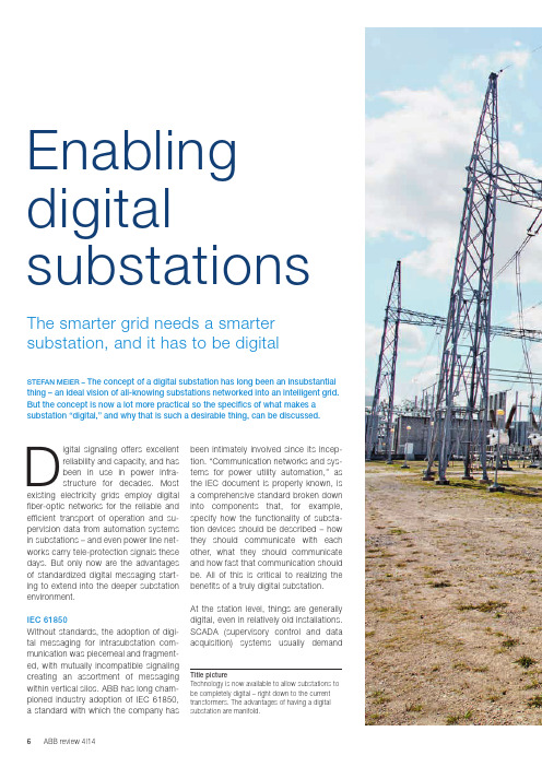
been intimately involved since its incep-tion. “Communication networks and sys-tems for power utility automation,” as the IEC document is properly known, is a comprehensive standard broken down into components that, for example, specify how the functionality of substa-tion devices should be described – how they should communicate with each o ther, what they should communicate and how fast that communication should be. All of this is critical to realizing the benefits of a truly digital substation.At the station level, things are generally digital, even in relatively old installations. SC ADA (supervisory control and data a cquisition) systems usually demand Digital signaling offers excellent reliability and capacity, and has been in use in power infra-structure for decades. Most existing electricity grids employ digital f iber-optic networks for the reliable and efficient transport of operation and su-pervision data from automation systems in substations – and even power line net-works carry tele-protection signals these days. But only now are the advantages of standardized digital messaging start-ing to extend into the deeper substation environment.IEC 61850Without standards, the adoption of digi-tal messaging for intrasubstation com-munication was piecemeal and fragment-ed, with mutually incompatible signaling creating an assortment of messaging within vertical silos. ABB has long cham-pioned industry adoption of IEC 61850, a standard with which the company has STEFAN MEIER – The concept of a digital substation has long been an insubstantial thing – an ideal vision of all-knowing substations networked into an intelligent grid. But the concept is now a lot more practical so the specifics of what makes a substation “digital,” and why that is such a desirable thing, can be discussed.The smarter grid needs a smarter substation, and it has to be digital Enabling digital substations Title picture Technology is now available to allow substations to be completely digital – right down to the currenttransformers. The advantages of having a digital substation are manifold.FOCS Robustness and reliability requirements apply to new technologies such as ABB’s fiber-optic current sensor (FOCS) too. A FOCS [1] can directly monitor current running through a high-voltage line with-out having to involve a current trans-former (CT) to step down the current to a measurable value. Eliminating the C T also eliminates the risk of open C T cir-cuits, in which life-threatening voltages can occur, and so increases safety.A FOCS exploits the phase shift in polar-ized light introduced by an electromag-netic field (the Faraday effect). The shiftis in direct proportion to the current flow-ing in the high-voltage line, around whichthe fiber carrying the light is wrapped.The measurement is digitized right atthe source and transmitted as a digitalsignal, via the process bus, to the pro-tection and control IEDs, as well as therevenue meters.Such an optical C T takes up a lot lessspace than its analog equivalent. It caneven be integrated into a disconnectingcircuit breaker (as ABB did in 2013) tocombine the functions of circuit breaker,current transformer and disconnector inone device – halving the size of a newsubstation.The FOCS is one of a range of noncon-ventional instrument transformers (NCITs)that can make things entirely digital.NCITs have to be every bit as reliable asthe equipment being replaced – and theydigital information and ABB has been selling fiber-optic “backbones” for more than two decades.Between the station level and the bays, fibers can carry digital data – conforming to IEC 61850 – but to become a true digital substation the standard has to e xtend even further.Deep digitalThe world beyond the bays is still pre-dominately analog. The conventional pri-mary equipment, like current and voltage transformers, is connected back to intel-ligent electronic devices (IEDs) using par-allel copper wires carrying analog voltage signals ➔1a. The IEDs receiving that data perform first-level analysis and often pro-vide the gateway into a digital world.But there is little advantage in keeping the data in analog form for so long and to properly earn the title of “digital substa-tion” the transition to digital must takeplace as soon as the data is gathered ➔1b.Through permanent system supervision, digital equipment reduces the need for manual intervention and the adoption of the all-digital process bus allows sensitive equipment to be relocated into the bays. The digital equipment that has to bel ocated out in the yard must be easy to fit, and every bit as robust and reliable as the analog equipment it is replacing or inter-facing to ➔2.Digital signaling offers excellent reliability and capacity, and has been in use in power infrastruc-ture for decades.1a Today 1b Tomorrow670 series 670 series REB500REB500650 series 650 seriescurrent transformer, arcing may occur as dangerously high voltages build and a copper line can suddenly carry high volt-age, putting workers and equipment at risk. Less copper brings greater safety.The digital substation dispenses with cop-per by using the digital process bus, which might use fiber optics or a wireless net-work, such as ABB’s Tropos technology.Just the removal of copper can, in some circumstances, justify the switch to digital. Going digital can cut the quantity of cop-per in a substation by 80 percent – a sub-stantial cost saving and, more importantly, a significant safety enhancement.The process bus also adds flexibility: Digital devices can speak directly to each other ➔3. For this, IEC 61850 defines the GOOSE (generic object-orientatedsubstation events)protocol for fasttransmission of bi-nary data. Part 9-2of the standard de-scribes the trans-mission of sampledvalues over Ether-net. These principlesensure the timelydelivery of high-pri-ority data via other-wise unpredictableEthernet links. ABB’s ASF range of E thernet switches fully supports this crit-ical aspect of substation messaging.are: Over the past decade ABB has sup-plied more than 300 NC ITs (combined current and voltage sensors fitted into gas-insulated switchgear) for use in Queensland, Australia, and the utility has yet to see a single failure in the primarysensor. Extensive use of NCITs makes a substation simpler, cheaper, smaller and more efficient.Not everything can be digital – analog data will continue to arrive from conven-tional current and voltage transformers, for example. But there is no reason for wholesale replacement when a stand-alone merging unit can perform the tran-sition to digital right beside the existinginstrument transformer. Fiber optics can then replace the copper cables connect-ing the primary equipment to the protec-tion and control IEDs.Process bus As a conductor, every bit of copper in a substation is a potential risk. For exam-ple, where current is incorrectly discon-nected, such as with an open secondary A FOCS can direct-ly monitor current running through a high-voltage line without having to involve a current transformer to stepdown the current to a measurable value.2 New equipment destined for use out in the yard is exposed to the elements so has to be very robust.ABB has long championed industry adoption of IEC 61850, a standard with which the company has been intimately involved since its inception.Installations ABB has been heavily involved in IEC 61850 since its inception. The stan-dard is essential to ensure that utilities can mix and match equipment from dif-ferent suppliers, but, through compli-ance testing, it also provides a bench-mark against which manufacturers can be measured.ABB deployed the first commercial IEC 61850-9-2 installation in 2011 at the Loganlea substation, for Powerlink Queens-land. The use of ABB’s IEC 61850-9-2- compliant merging units and IEDs, not to mention NCITs, makes the deployment a landmark in the evolution of substation design.That project was part of an upgrade of an existing station, an upgrade that saw it move into an IEC 61850 future, adopting digital standards for effective future-proof-ing. ABB created a retrofit solution based on specifications from Powerlink that can be applied to another five Powerlink substa-tions when they are ready for refitting.Two of those stations, Millmerran and Bulli Creek, were already upgraded in 2013 and 2014, respectively. The refurbished sub-stations have a MicroSCADA Pro SYS600 system and RTU560 gateway that manage Relion 670 protection and control IEDs, with REB500 busbar protection. These all communicate over IEC 61850-9-2 to the merging units and over IEC 61850 to the station-level devices. A fully digital substation is smaller, more reliable, has a reduced life-cycle cost and is simpler to maintain and extend than an analog one. It offers increased safety and is more efficient than its ana-log equivalent.Not every substation needs to be cata-pulted into a wholesale digital world – it depends on the substation size and type, and whether it is a new station or a retrofit of the secondary system. Different ap-proaches and solutions are required. ABB’s extensive IEC 61850 experience and portfolio of NCITs, merging units, pro-tection and control IEDs as well as station automation solutions eases utilities into the digital world. Flexible solutions allow utilities to set their own pace on their waytoward the digital substation.3 IEC 61850 makes the fully digital substation a reality.Stefan MeierABB Power Systems Baden, Switzerland *******************.com An optical CT takes up a lot less space than its analog equivalent and can even be integrated into a disconnecting circuit breaker to combine the func-tions of circuit breaker, current transformer and disconnector in one device – halv-ing the size of a new substation.Reference [1] S. Light measures current – A fiber-optic current sensor integrated into a high-voltage circuit breaker. Available: /global/scot/scot271.nsf/veritydisplay/0d948cedb40451cec1257ca900532dd0/$file/12-17%201m411_EN_72dpi.pdf。
IEC61850通信规约转换软件Demo使用手册xt
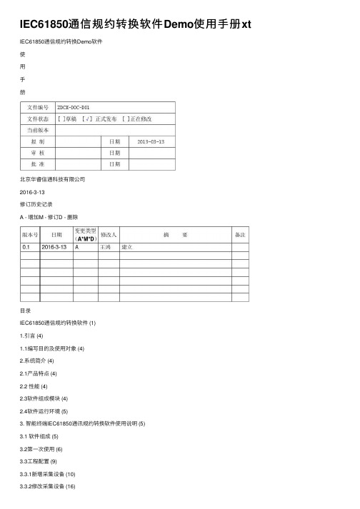
IEC61850通信规约转换软件Demo使⽤⼿册xt IEC61850通信规约转换Demo软件使⽤⼿册北京华睿信通科技有限公司2016-3-13修订历史记录A - 增加M - 修订D - 删除⽬录IEC61850通信规约转换软件 (1)1.引⾔ (4)1.1编写⽬的及使⽤对象 (4)2.系统简介 (4)2.1产品特点 (4)2.2 性能 (4)2.3软件组成模块 (4)2.4软件运⾏环境 (5)3. 智能终端IEC61850通讯规约转换软件使⽤说明 (5)3.1 软件组成 (5)3.2第⼀次使⽤ (6)3.3⼯程配置 (9)3.3.1新增采集设备 (10)3.3.2修改采集设备 (16)3.3.3配置信息向装置下载 (16)1.引⾔1.1编写⽬的及使⽤对象本⽂档介绍智能电⼦设备IEC61850规约转换软件的组成模块,性能指标和主要功能,并详细介绍modbus规约转换为IEC61850规约的使⽤⽅法,适⽤于⼯程技术⼈员使⽤。
2.系统简介2.1产品特点●满⾜最新DL/T 860(IEC61850)通讯标准●完全⽀持国际标准IEC61850规约,并可实现其它规约对IEC 61850规约的转换。
●⽀持modbus TCP/IP ,modbus RTU2.2 性能a.系统容量●同时接⼊的终端装置数⽬:100(在pc机下vmvare fedora7 cpu2G 内存2G)b.时间特性●随系统⾃动启动●默认检索实时数据的周期为最⼩30秒钟,此参数可以设置●检索报警数据的周期为即时上送c.计算机系统(在pc机下vmvare fedora7 cpu2G 内存2G)●系统可⽤率≥99%●CPU负荷率≤25%●⽹络负荷率≤5%d.通讯能⼒●⽀持⽹络●⽀持串⼝2.3软件组成模块IEC61850规约转换Demo软件主要实现由modbus协议转换成IEC 61850协议,其数据的交换通过共享内存⽅式来实现,涉及到三个模块采集模块、实时库和61850服务模块。
许继iec61850-9-2(le版)通信规约

用于 80 点采样率的采样值的传送。
用于 256 点采样率的采样值的传送。 对应于 TCTR 和 TVTR 中的 HzRtg 数据属性。
3.5 IED 一个 MU 是一个 LD。允许一个 IED 中存在多个 MU(LD)。气
时钟源: 典型的时钟源的 1PPS 产生于 GPS 接收器。它具备±1μs 的精度。
同步运行:
第 4页
许继电气
许继 IEC61850-9-2(LE 版)通信规约
MU 与 Global 1PPS 同步时,SV 报文中的 SmpSynch 属性赋成 2。MU 与 Local 1PPS 同步时,SV 报文中的 SmpSynch 属性赋成 1。
FALSE FALSE
注解
配置,采用 9-2 中的推荐值: 01-0C-CD-04-xx-xx
3.3 运行和对时约定 3.3.1 运行模式 Mod
支持如下属性: ON:正常运行状态,此时 MU 激活,发送数据。 TEST:测试状态,MU 发送数据,数据的 q 属性“test”标志置 TRUE。 OFF:复位状态,MU 不发数据。
非同步运行: MU 收不到同步脉冲信号,SV 报文中的 SmpSynch 属性赋成 0。
3.3.3 派生数据 如果采样数据不是采集实际的测量量,而是通过计算派生的,则对应 SAV
的 q 属性中的 derived 标志应置为 TRUE。
3.4 MU 的配置
表 7:需要配置的 MU 的参数
参数名
值域
LDName
注解
DataSet 定义固定不变
第 3页
许继电气
许继 IEC61850-9-2(LE 版)通信规约
KW-61850协议转换器软件使用手册
最低配置: CPU:Intel Pentium III 800m 内存:128M 硬盘:20G 显示器:11 寸以上
4
第三章 安装与卸载
珠海市科为电力科技有限公司
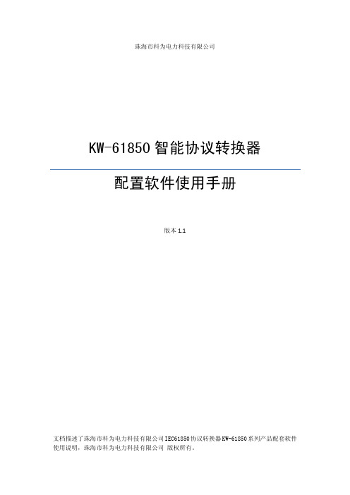
KW-61850 智能协议转换器 配置软件使用手册
版本 1.1
文档描述了珠海市科为电力科技有限公司 IEC61850 协议转换器 KW-61850 系列产品配套软件 使用说明,珠海市科为电力科技有限公司 版权所有。
目录
第一章 简介 ............................................................................................................................. 3 第二章 运行平台 ..................................................................................................................... 4 第三章 安装与卸载 ................................................................................................................. 5
3.1 软件的安装........................................................................................................................5 3.2 软件的卸载........................................................................................................................6 第四章 用户界面 ..................................................................................................................... 7 4.1 主界面.................................................................................................................................7 4.2 配置界面.............................................................................................................................8 4.3 管理界面.............................................................................................................................9 第五章 配置 ........................................................................................................................... 11 5.1 配置下行通道...................................................................................................................11 5.2 建立计算表达式..............................................................................................................13 5.2 配置上行通道...................................................................................................................14 5.2 映射上下行.......................................................................................................................14 5.3 IEC61850 服务器建模 .....................................................................................................15 第六章 管理 ........................................................................................................................... 20 6.1 登录..................................................................................................................................20 6.2 下载配置文件..................................................................................................................21 6.3 读取配置文件..................................................................................................................21 6.4 管理网卡..........................................................................................................................22 6.5 修改用户名和密码..........................................................................................................22 6.6 远程升级..........................................................................................................................23 6.7 校对时间..........................................................................................................................23 6.8 重启..................................................................................................................................23 6.9 查看和仿真实时数据......................................................................................................23 6.10 查看通道报文................................................................................................................24
最新IEC61850建模工具软件用户手册
I E C61850建模工具软件用户手册IEC 61850建模工具用户手册山东理工大学2013.03目录1.简介 ........................................................................................................................- 1 -2. IEC 61850配置功能 ..............................................................................................- 1 -2.1 界面..............................................................................................................- 1 -2.2 CID文件配置...............................................................................................- 2 -2.3 CID文件树形结构.......................................................................................- 3 -2.4 逻辑数据配置..............................................................................................- 5 -2.4.1 增加...................................................................................................- 5 -2.4.2 修改...................................................................................................- 7 -2.4.3 删除...................................................................................................- 8 -2.4.4 导出...................................................................................................- 9 -2.4.5 导入...................................................................................................- 9 -2.5逻辑设备维护 .......................................................................................... - 10 -2.5.1 增加................................................................................................ - 11 -2.5.2 删除................................................................................................ - 12 -2.5.3 修改................................................................................................ - 13 -2.6逻辑节点维护 .......................................................................................... - 13 -2.6.1 增加................................................................................................ - 14 -2.6.2 删除.................................................................................................- 17 -2.6.3 修改.................................................................................................- 17 -3.CID文件生成....................................................................................................... - 18 -4. CID文件格式...................................................................................................... - 18 -4.1 CDC、FC配置文件内容........................................................................... - 18 -4.2 CID文件模版内容.....................................................................................- 20 -4.3 生成CID文件内容....................................................................................- 20 -1.简介主要完成61850FTU逻辑数据的配置,配置信息生成excel文件,61850FTU配置程序通过读取excel信息保存到配置文件中。
IEC61850规约及过程层规约实现方式
Sieyuan Electric
定值服务 SelectActiveSG (选择激活定值组) SelectEditSG (选择编辑定值组) SetSGValuess (设置定值组值) ConfirmEditSGValues (确认编辑定值组值) GetSGValues (读定值组值) GetSGCBValues (读定值组控制块值)服务;
2020年3月4日
15
MMS-报告服务
数据帧定义 多帧传送, 传送对象、数值及原因
SHR思源弘瑞
6
MMS-定值服务
ActSG EditSG NumOfSG CnfEdit
SHR思源弘瑞
Sieyuan Electric
2020年3月4日
变压器档位 保护软压板 装置复归 断路器隔离开关 通用GGIO开出
Sieyuan Electric
2020年3月4日
25
MMS-控制服务
遥控返回的原因码应统一使用
• 监控在失败时显示错误码信息,便于分析 • 如五防闭锁、同期失败等
部分不太使用的错误码 • Blocked-by-mode (8) • Blocked-by-process (9) • Blocked-by-health (13) • ….与内外模型一致相关
模型 TPAA——MMS MCAA——GOOSE/SMV
规范 应支持association、release、abort服务; 支持同时与不少于16个客户端建立连接; 当装置与客户端的通讯意外中断时:装置通 讯故障的检出时间不大于1分钟,通讯故障客 户端检出时间不大于1分钟;
- 1、下载文档前请自行甄别文档内容的完整性,平台不提供额外的编辑、内容补充、找答案等附加服务。
- 2、"仅部分预览"的文档,不可在线预览部分如存在完整性等问题,可反馈申请退款(可完整预览的文档不适用该条件!)。
- 3、如文档侵犯您的权益,请联系客服反馈,我们会尽快为您处理(人工客服工作时间:9:00-18:30)。
IEC61850通信规约转换软件Demo使用手册xt
IEC61850通信规约转换Demo软件
使
用
手
册
北京华睿信通科技有限公司
2016-3-13
修订历史记录
A - 增加M - 修订D - 删除
目录
IEC61850通信规约转换软件 (2)
1.引言 (5)
1.1编写目的及使用对象 (5)
2.系统简介 (6)
2.1产品特点 (6)
2.2 性能 (6)
2.3软件组成模块 (6)
2.4软件运行环境 (7)
3. 智能终端IEC61850通讯规约转换软件使用说明 (7)
3.1 软件组成 (7)
3.2第一次使用 (8)
3.3工程配置 (11)
3.3.1新增采集设备 (11)
3.3.2修改采集设备 (18)
3.3.3配置信息向装置下载 (18)
1.引言
1.1编写目的及使用对象
本文档介绍智能电子设备IEC61850规约转换软件的组成模块,性能指标和主要功能,并详细介绍modbus规约转换为IEC61850规约的使用方法,适用于工程技术人员使用。
2.系统简介
2.1产品特点
●满足最新DL/T 860(IEC61850)通讯标准
●完全支持国际标准IEC61850规约,并可实现其它规约对IEC 61850规约的
转换。
●支持modbus TCP/IP ,modbus RTU
2.2 性能
a.系统容量
●同时接入的终端装置数目:100(在pc机下vmvare fedora7 cpu2G 内
存2G)
b.时间特性
●随系统自动启动
●默认检索实时数据的周期为最小30秒钟,此参数可以设置
●检索报警数据的周期为即时上送
c.计算机系统(在pc机下vmvare fedora7 cpu2G 内存2G)
●系统可用率≥99%
●CPU负荷率≤25%
●网络负荷率≤5%
d.通讯能力
●支持网络
●支持串口
2.3软件组成模块
IEC61850规约转换Demo软件主要实现由modbus协议转换成IEC 61850协议,其数据的交换通过共享内存方式来实现,涉及到三个模块采集模块、实时库和61850服务模块。
其数据流向是采集模块(如电能量modbus master)按照用户提供的modbus协议与终端里的modbus程序进行通讯,获得电能量信息,并保存在实时库里,同时根据实时库里每个智能电子终端对应的61850DA属性,写入到61850的实时库中,这样61850服务程序就能及时更新其对应的DA值,并作相应的处理,对外提供相应的服务
图一软件结构图
2.4软件运行环境
IEC61850规约转换软件正常运行时所需要的最低软硬件配置要求见下表
3. IEC61850规约转换软件使用说明
3.1 软件组成
程序包组成如下图所示
图二整个程序包组成
mmsserver: IEC61850服务程序,实现iec61850服务功能,对外提供61850服务。
commserver: 采集程序,负责与终端按照modbus协议进行通讯,获得实时数据。
sysmgr:系统维护程序。
工程配置文件:在运行程序以及维护程序所在的目录下包含了以下子目录,每个子目录包含了系统运行所需要的配置文件(注意linux下目录区分大小写)
config目录:包含prjcfg.txt工程目录信息
dbcfg目录:dbcfg.xml,是系统基础数据库库表信息,不要对它作任何修改。
FileServer目录:61850文件服务的根目录,需要上传的文件及其子目录都放在这个目录下
project目录:工程的根目录,下面放工程子目录比如yp目录,在具体工程子目录下由以下目录构成
config目录:存放配置好的采集设备参数信息
dbcfg目录:存放工程配置好的实时库配置信息
dbdata目录:存放工成配置好生成的实时库数据文件
3.2正式版本第一次使用
使用本产品前需要对软件进行注册。
按照如下步骤进行
第一步:将运行程序以及工程配置文件拷贝到所有需要注册的装置上。
第二步:在每个装置上分别运行sysmgr程序:
第三步:在PC机上运行Remotereg.exe程序(要保证pc机与各个装置网络畅通),该程序启动后会自动搜索没有注册的装置,并显示出来,如下图四,软后点击导出注册号信息,指定所要保存的文件名如图五,然后将保存的文件给北京华睿信通科技有限公司进行授权,收到授权文件后,点击导入注册信息,选择收到的授权文件,系统会显示相应的注册信息如图六,随后点击注册,等待系统远程注册,注册完毕后在下方信息栏中会显示注册结果如图七。
图四软件注册
图五保存文件
图六导入注册信息
图七注册结果
注册程序其他按钮说明:
搜索未注册装置:搜索与PC机网络相通的还没有注册的装置,注册过的装置不会返回信息。
搜索所有装置:搜索与PC机网络相通的所有装置。
此外也可以进行单台装置注册,首先选择需要注册的装置,将选中的注册号发送给北京华睿雅威公司,获得授权号,并输入到注册码里,然后点击输入,最后点击注册。
图一产品注册
3.3工程配置
运行sysmgr程序,展开数据采集设备的树形目录,点击鼠标右键增加或修改采集设备的属性。
(演示版本不具备增加设备功能,可以修改设备配置信息)
3.3.1新增采集设备
根据工程需要,可以增加采集设备,具体步骤如下:
第一步:新增采集设备。
此步骤可以设置采集设备的名称,采集数据的周期等时间参数,一般此步骤的时间参数采用默认即可。
第二步:选择通信方式。
一般采用以太网TCP-客户端的通信方式。
第三步:设置TCP参数。
此步骤需要设置采集程序与电能量终端进行通讯的IP 地址和通信端口号,因为在同一机器上IP地址设为127.0.0.1,通信端口号根据电能量终端提供的端口,默认采用502,其他参数默认即可。
第四步:设置协议参数。
采用下面默认值即可
第五步:点击工具栏上的保存按钮,将新增加的装置信息保存到配置文件中,第六步:配置61850实时数据库。
切换到实时数据库页面,选择61850实时库 右键新建数据库。
输入数据库名称默认用61850db
新建数据库表-》选择61850DA值,根据实际情况输入最大记录数,
61850参数配置:选择61850配置设置61850相关参数
61850模型文件:根据工程实际,选正确模型文件
服务端口:默认采用102
接收间隔:是指间隔多长时间都tcp端口,看是否有数据到达,默认采用100ms
超时(s):-1表示不进行数据收发超时判断,如果要设置则根据实际现场数据交互的时间间隔来设置,比如61850服务端与客户端平均60s 钟才发生一次数据交互,则这个值应该设为比60s大的数比如65。
其他的参数主要是为了检测用的,实际工程中都采用默认值即可。
第八步:配置采集实时库表,选择实时库,右键选择新建数据库表,从下拉表中选择Modbus模拟量
根据实际情况设置最大记录数,其他采用默认值增加记录。
在数据库中增加记录,根据实际情况修改实时库中的信息并保存。
根据实时数据库表的内容修改新装置记录中的内容。
修改表内容的便捷操作方法如下,将新增装置的数据库表导出,请留心系统提示的导出位置及导出文件名字然后就可以在excel中编辑数据文件,然后再将数据库表导入并保存即可。
3.3.2修改采集设备
可以参考新增采集设备操作。
3.3.3配置信息向装置下载(windows版本不需要此操作)
当所有的信息都配置好了之后,就可以将配置信息下载到装置上。
首先要确保装置上的sysmgr程序在运行,其他程序都已经关闭。
其次与装置建立连接
连接成功后就可以下载信息,如图点击工具栏中的下载按钮
点击确定,系统就会开始下载配置信息。
4.系统运行
系统配置好之后,就可以运行了
4.1首先运行mmsserver.exe
4.2在运行commserver.exe之前,要确保sysmgr所配置的ip地址对应的Modbus
slave已经运行
4.3运行viewrtdb可以查看接收到的数据
北京华睿信通科技有限公司 IEC 61850通信规约转换软件使用手册
第 21 页共 21 页。