电子电气类专业毕业设计外文翻译
附录一:外文原文
Super capacitors - An Overview
Key words: Electrostatic capacitor; Electrolytic capacitor; Ceramic capacitor;
Electrical double layer capacitor; Super Capacitor
1.INTRODUCTION
This paper offers a concise review on the renaissance of a conventional capacitor toelectrochemical double layer capacitor or super capacitor. Capacitors are fundamental electrical circuitelements that store electrical energy in the order of microfarads and assist in filtering. Capacitors havetwo main applications; one of which is a function to charge or discharge electricity. This function isapplied to smoothing circuits of power supplies, backup circuits of microcomputers, and timer circuitsthat make use of the periods to charge or discharge electricity. The other is a function to block the flowof DC. This function is applied to filters that extract or eliminate particular frequencies. This isindispensable to circuits where excellent frequency characteristics are required. Electrolytic capacitorsare next generation capacitors which are commercialized in full scale. They are similar to batteries in cell construction but the anode and cathode materials remain the same. They are aluminum, tantalum and ceramic capacitors where they use solid/liquid electrolytes with a separator between two symmetrical electro des.
An electrochemical capacitor (EC), often called a Super capacitor or Ultra capacitor, stores electrical charge in the electric double layer at a surface-electrolyte interface, primarily in high-surface-area carbon. Because of the high surface area and the thinness of the double layer, these devices can have very a high specific and volumetric capacitance. This enables them to combine a previously unattainable capacitance density with an essentially unlimited charge/discharge cycle life. The operational voltage per cell ,limited only by the breakdown potential of the electrolyte, is usually<1 or <3 volts per cell for aqueous or organic electrolytes respectively.
The concept of storing electrical energy in the electric double layer that is
formed at the interface between an electrolyte and a solid has been known since the late 1800s. The first electrical device using double-layer charge storage was reported in 1957 by H.I. Becker of General Electric (U.S. Patent 2,800,616).Unfortunately, Becker’s device was imp ractical in that, similarly to a flooded battery, both electrodes needed to be immersed in a container of electrolyte, and the device was never comercialised.
Becker did, however, appreciate the large capacitance values subsequently achieved by Robert A. Rightmire, a chemist at the Standard Oil Company of Ohio (SOHIO), to whom can be attributed the invention of the device in the format now commonly used. His patent (U.S. 3,288,641), filed in 1962 and awarded in late November 1966, and a follow-on patent (U.S. Patent 3,536,963) by fellow SOHIO researcher Donald L. Boos in 1970, form the basis for the many hundreds of subsequent patents and journal articles covering all aspects of EC technology.
This technology has grown into an industrywith sales worth severalhundred million dollars per year. It is an in dustry that is poised today for rapid growth in the near term with the expansion of power quality needs and emerging transportation applications.
Following the commercial introduction of NEC’s Super Capacitor in 1978, under licence from SOHIO, EC have evolved through several generations of designs. Initially they were used as back-up power devices for v is for cells ranging in size from small millifarad size devices with exceptional pulse power performance up to devices rated at hundreds of thousands of farads, with systems in some applications operating at up to 1,500 volts. The technology is seeing increasingly broad use, replacing batteriesolatile clock chips and complementary metal-oxide-semiconductor (CMOS) computer memories. But many other applications have emerged over the past 30 years, including portable wireless communication, enhanced power quality for distributed power generation systems, industrial actuator power sources, and high-efficiency energy storage for electric vehicles(EVs) and hybrid electric vehicles (HEVs).Overall, the unique attributes of ECs often complement the weaknesses of other power sources like batteries and fuel cells.
Early ECs were generally rated at a few volts and had capacitance values measured from fractions of farads up to several farads. The trend today in some cases and in others complementing their performance.
The third generation evolution is the electric double layer capacitor, where the electrical charge stored at a metal/electrolyte interface is exploited to construct a
storage device. The interface can store electrical charge in the order of 6
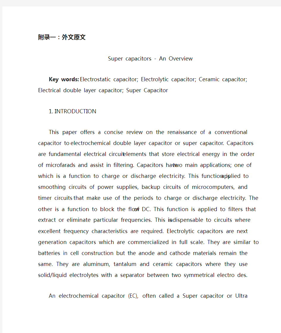
10Farad. The main component in the electrode construction is activated carbon. Though this concept was initialized and industrialized some 40 years ago, there was a stagnancy in research until recent times; the need for this revival of interest arises due to the increasing demands for electrical energy storage in certain current applications like digital electronic devices, implantable medical devices and stop/start operation in vehicle traction which need very short high power pulses that could be fulfilled by electric double layer capacitors. They are complementary to batteries as they deliver high power density and low energy density. They also have longer cycle life than batteries and possess higher energy density as compared to conventional capacitors. This has led to new concepts of the so-called hybrid charge storage devices in which electrochemical capacitor is interfaced with a fuel cell or a battery. These capacitors using carbon as the main electrode material for both anode and cathode with organic and aqueous electrolytes are commercialized and used in day to-day applications. Fig.
1 presents the three types of capacitors depicting the basic differences in their design and construction.
Figure 1.Schematic presentation of electrostatic capacitor, electrolytic capacitor and electrical double layer capacitor.
EDLCs, however suffer from low energy density. To rectify these problems, recently researchers try to incorporate transition metal oxides along with carbon in the electrode materials. When the electrode materials consist of transition metal oxides, then the electrosorption or redox processes enhance the value of specific capacitance ca. 10 -100 times depending on the nature of oxides. In such a situation, the EDLC is called as super capacitor or pseudo capacitor . This is the fourth generation capacitor. Performance of a super capacitor combines simultaneously two kinds of energy storage, i.e. non-faradic charge as in EDLC capacitors and faradaic charge similar to
processes proceeding in batteries. The market for EC devices used for memory protection in electronic circuitry is about $150-200 million annually. New potential applications for ECs include the portable electronic device market, the power quality market, due particularly to distributed generation and low-emission hybrid cars, buses and trucks. There are some published reviews on capacitors and super capacitors . In the present overview, the evolution of electrochemical double layer capacitors starting from simple electrostatic capacitors is summarized.
2. EXPERIMENTAL PART
The invention of Leiden jar in 1745 started the capacitor technology; since then, there has been tremendous progress in this field. In the beginning, capacitors are used primarily in electrical and electronic products, but today they are used in fields ranging from industrial application to automobiles, aircraft and space, medicine, computers, games and power supply circuits. Capacitors are made from two metallic electrodes (mainly Si) placed in mutual opposition with an insulating material (dielectric) between the electrodes for accumulating an electrical charge. The basic equation relating to the capacitors is:
C = εS/d (1)
where C(μF) is the electrostatic capacity, the dielectric constant of the dielectric, S (cm2) the surface area of the electrode and d (cm) the thickness of the dielectric. The charge accumulating principle can be described as follows: when a battery is connected to the capacitor, flow of current induces the flow of electrons so that electrons are attracted to the positive terminal of the battery and so they flow towards the power source. As a result, an electron deficiency develops at the positive side, which becomes positively charged and an electron surplus develops at the negative side, which becomes negatively charged. This electron flow continues until the potential difference between the two electrodes becomes equal to the battery voltage. Thus the capacitor gets charged. Once the battery is removed, the electrons flow from the negative side to the side with an electron deficiency; this process leads to discharging. The conventional capacitors yield capacitance in the range of 0.1 to 1 μ
F with a voltage range of 50 to 400 V. Various materials such as paper (ε, 1.2-2.6), paraffin (ε 1.9-2.4), polyethylene (2.2-2.4), polystyrene (ε, 2.5-2.7), ebonite (ε, 2-3.5), polyethylene tetraphtharate (ε,3.1-3.2), water (ε, 80) sulfur(ε, 2-4.2), steatite porcelain (ε, 6-7), Al porcelain (ε, 8-10), mica(ε, 5-7)and insulated mineral oil (ε, 2.2-2.4) are used as dielectrics in capacitors.
The capacitance output of these silicon based capacitors is limited and has to cope with low surface-to volume ratios of these electrodes. To increase the capacitance, as per eq., one has to increase to ?or S and decrease; however the ?value is largely determined by the working voltage and cannot be tampered. When aiming at high capacitance densities, it is necessary to combine the mutual benefits achieved with a high permittivity insulator material and an increased effective surface area. With Si as the substrate material, electrochemical etching produces effective surface area. The surface area of this material gets enlarged by two orders of magnitude compared to unetched surface. Electrochemically formed macroporous Si has been used for the preparation of high aspect ratio capacitors with layered SiO2/Si3N4/SiO2 insulators. Research work on the modification of conventional capacitors to increase the specific capacitance is also in progress. Approximately 30 times higher capacitance densities are reported recently for Si/Al2O3/ZnO: Al capacitor where Si is electrochemically etched porous one. Another way identified to increase the surface area of the electrodes is to form anodically formed oxides (Al, Ta); however, ceramic capacitors are based on the high dielectric constant rather than the electrode area.
3. ELECTROLYTIC CAPACITORS
The next generation capacitors are the electrolytic capacitors; they are of Ta, Al and ceramic electrolytic capacitors. Electrolytic capacitors use an electrolyte as conductor between the dielectrics and an electrode. A typical aluminum electrolytic capacitor includes an anode foil and a cathode foil processed by surface enlargement and or formation treatments. Usually, the dielectric film is fabricated by anodizing high purity Al foil for high voltage applications in boric acid solutions. The thickness of the dielectric film is related to the working voltage of the aluminum electrolytic capacitor. After cutting to a specific size according to the design specification, a laminate made up of an anode foil, a cathode foil which is opposed to the dielectric film of the anode foil and a separator interposed between the anode and cathode foils, is wound to provide an element. The wound element does not have any electrical
characteristics of electrolytic capacitor yet until completely dipped in an electrolyte for driving and housed in a metallic sheathed package in cylindrical form with a closed-end equipping a releaser. Furthermore, a sealing material made of elastic rubber is inserted into an open-end section of the sheathed package and the open-end section of the sheathed package by drawing, whereby an aluminum electrolytic capacitor is constituted. Electrolytic aluminum capacitors are mainly used as power supplies for automobiles, aircraft, space vehicles, computers, monitors, motherboards of personal computers and other electronics.
There are two types of tantalum capacitors commercially available in the market; wet electrolytic capacitors which use sulfuric acid as the electrolyte and solid electrolytic capacitors which use MnO2 as the solid electrolyte. Though the capacitances derived from both Ta and Al capacitors are the same, Ta capacitors are superior to Al capacitors in temperature and frequency characteristics. For analog signal systems, Al capacitors produce a current-spike noise which does not happen in Ta capacitors. In other words, Ta capacitors are preferred for circuits which need high stability characteristics. The total world wide production of Al electrolytic capacitors amounts to US$ 3.8 billion, 99% of which are of the wet type. Unlike Ta solid electrolytic capacitors, the solid electrolyte materials used are of organic origin; polypyrrole, a functional polymer and TCNQ (7,7, 8, 8- tetracyanoquniodimethane) an organic semiconductor. Next, MnO2 solid electrolyte material is formed on the surface of that dielectric layer and on top of that a layer of polypyrrole organic solid electrolyte material is formed by electrolytic synthesis. Following this, the positive and negative electrodes are mounted to complete the electronic component. However, the capacitances of these electrolytic capacitors are in the range 0.1 to 10F with a voltage profile of 25 to 50 V.
The history of development of electrolytic capacitors which were mass produced in the past as well as today is presented by S. Niwa and Y. Taketani . Many researchers try to improve the performance of these electrolytic capacitors by modifying the electrode or electrolyte. Generally, the increases in effective surface area (S) are achieved by electrolytic etching of aluminum substrate before anodization, but now it faces with the limit. It is also very difficult to decrease d because the d value is largely decided when the working voltages are decided. Increase in may be a possible routine to form composite dielectric layers by incorporating relatively large value compounds. Replacement of MnO2 by polypyrrole solid electrolyte was reported to reduce electrostatic resistance due to its higher conductivity; aromatic
sulfonate ions were used as charge compensating dopant ions .A tantalum capacitor with Ta metal as anode, polypyrrole as cathode and Ta2O5 dielectric layer was also reported. In the Al solid electrolytic capacitors, polyaniline doped with inorganic and organic acids was also studied as counter electrode. In yet another work, Al solid electrolytic capacitor with etched Al foil as anode, polyaniline / polypyrrrole as cathode and Al2O3 as dielectric was developed. Ethylene carbonate based organic electrolytes and -butyrolactone based electrolytes have been tried as operating electrolytes in Al electrolytic capacitors. Masuda et al. have obtained high capacitance by electrochemically anodizing rapidly quenching Al-Ti alloy foil. Many researchers have tried the other combination of alloys such as Al-Zr, Al-Si, Al-Ti, Al-Nb and Al-Ta composite oxide films. Composite oxide films of Al2O3-(Ba0.5Sr0.5TiO3) and Al2O3- Bi4Ti3O12 on low-voltage etched aluminum foil were also studied. Nb-Ta-Al for Ta electrolytic capacitors was also tried as anode material .
A ceramic capacitor is a capacitor constructed of alternating layers of metal and ceramic, with the ceramic material acting as the dielectric. Multilayer ceramic capacitors (MLCs) typically consist of ~100 alternate layers of electrode and dielectric ceramics sandwiched between two ceramic cover layers. They are fabricated by screen-printing of electrode layers on dielectric layers and co-sintering of the laminate. Conventionally, Ag-Pd is used as the electrode material and BaTiO3 is used as the dielectric ceramic. From 2000 onwards, the MLCs market has been growing in pace with the exponential development of communications. They are produced in the capacitance range of 10 F (normally the range of Ta and Al electrolytic capacitors); they are highly useful in high frequency applications. Historically, a ceramic capacitor is a two-terminal non-polar device. The classical ceramic capacitor is the disc capacitor. This device predates the transistor and was used extensively in vacuum-tube equipment (e.g radio receivers) from c. a. 1930 through the 1950s and in discrete transistor equipment from the 1950s through the 1980s. As of 2007, ceramic disc capacitors are in widespread use in electronic equipment, providing high capacity and small size at low price compared to the other types.
The other ceramic materials that have been identified and used are CaZrO3, MgTiO3, SrTiO3 etc. A typical 10 F MLC is a chip of size (3.2 x 1.6 x 1.5 mm). Mn, Ca, Pd , Ag etc are some of the other internal electrodes used. Linear dielectrics and antiferroelectrics based o strontium titante have been developed for high voltage disk capacitors. These are applicable for MLCs with thinner layers because of their high coercive fields. One of the most critical material processing parameters is the degree
of homogeneous mixing of additive in the slurry. The binder distribution in the green ceramic sheet, the degree of surface roughness, fine size nickel powder, formation of green sheet, electrode deposition ad sheet stacking etc play a crucial role in the process technology. Any one of these facts if mishandled would result in the failure of the device. For instance, providing a roughess of 5 m thick green sheet to 0.5 m is mandatory so that a smooth contact surface with the inner nickel electrode can be established. This is a very important factor in avoiding the concentration of electric filed at asperities, where the charge emission from the electrode is accelerated, resulting in short failure. Conventional sheet/printing method has a technical limit of producing a thickness around 1 m dielectric; in order to decrease the thickness further, thin film technologies like CVD, sputtering, plasma-spray etc has to be used.
The other types of capacitors are film capacitors which use thin polyester film and polypropylene film as dielectrics and meta-glazed capacitors which incorporate electrode plates made of film vacuum evaporated with metal such as Al. Films can be of polyester, polypropylene or polycarbonate make. Also capacitors are specified depending on the dielectric used such as polyester film capacitor, polypropylene capacitor, mica capacitor, metallized polyester film capacitor etc.
4. DOUBLE LAYER CAPACITORS
Electric/electrochemical double layer capacitor (EDLC) is a unique electrical storage device, which can store much more energy than conventional capacitors and offer much higher power densitythan batteries. EDLCs fill up the gap between the batteries and the conventional capacitor, allowing applications for various power and energy requirements i.e., back up power sources for electronic devices, load-leveling, engine start or acceleration for hybrid vehicles and electricity storage generated from solar or wind energy. EDLC works on the principle of double-layer capacitance at the electrode/electrolyte interface where electric charges are accumulated on the electrode surfaces and ions of opposite charge are arranged on the electrolyte side.
Figure 2.Charge storage mechanism of an EDLC cell under idle and charged conditions.
Fig. 2 shows the mechanism of charge storage in an EDLC cell and Fig. 3 shows the configuration of an typical EDLC cell. There are two main types of double layer capacitors as classified by the charge storage mechanism: (i) electrical double-layer capacitor; (ii) electrochemical double layer capacitor or super/pseudocapacitor. An EDLC stores energy in the double-layer at the electrode/electrolyte interface, whereas the supercapacitor sustains a Faradic reaction between the electrode and the electrolyte in a suitable potential window. Thus the electrode material used for the construction of the cell for the former is mainly carbon material while for the latter, the electrode material consist of either transition metal oxides or mixtures of carbon and metal oxides/polymers. The electrolytes can be either aqueous or non-aqueous depending on the mode of construction of EDLC cell.
Figure 3.Typical configuration of an EDLC cell
There are two general directions of interest. One is the long term goal of the development of electrical propulsion for vehicles, and the other is the rapid growth of portable electronic devices that require power sources with maximum energy content and the lowest possible size and weight.
5. CONCLUSIONS
According to a market survey by Montana, super capacitors are becoming a promising solution for brake energy storage in rail vehicles. The expected technological development outside railway sector is also shown to be highly dynamic: diesel electric vehicles, catenary free operation of city light rail, starting system for diesel engines, hybrid-electric cars, industrial applications, elevators, pallet trucks etc. The time horizon expected for development is next 5 to 10 years. The main development goals will be,
· long life time
· increase of the rated voltage
· improvements of the range of operating temperature
· increase of the energy and power densities
Very recently, hybrid car is introduced in the market but it is turned to be very expensive and out of common man’s reach. Shortage and cost of fossil fuels already instigated alternate technologies viable for traction purposes. In such a situation,
EDLCs are also useful to store energy generated from non-conventional energy sources. A future possibility of service centers set up for EDLC supply similar to petrol (as on date) is not far as the main setbacks in technology development may take a decade for fruitful results.
附录二:外文译文
超级电容器-概述
关键词:静电电容,电解电容器,陶瓷电容器,双电层 ,电容器,超级电容器1.引言
本文为电化学双层电容器或超级电容器提供在一台常规电容器,简明的介绍新生的电化学双电层电容器或超级电容器。电容器是存放电能并且协助过滤的根本电路元素。电容器有二个主要应用; 其中之一是充电或释放电的作用。这个作用适用于电源平流滤波电路,微型计算机备用电路和利用期间充电或释放电的定时器电路。其他是阻拦DC流程的作用。这个作用适用于提取或消灭特殊频率的过滤器。这是其中不可或缺的优秀电路所需的频率特性。电解电容是在充分的标度商业化的下一代电容器。他们类似电池在细胞建筑,但是阳极和负极材料依然保持不变。他们是铝,钽和两个陶瓷电容电解质的地方与他们所使用的液体固体分离器/ 对称的电极。
电化学电容器(EC),往往被称为超级电容器或超级电容,存储电荷的双层电荷在1层表面电解质界面,主要在高电位表面的碳。由于高电位表面是薄的双重层,所以这些设备可以有一个非常高的比和体积电容。这使得他们能够结合以前无法实现的电容用无限的电荷密度/放电循环寿命。每单元的工作电压,只受击穿电位电解质的影响,通常<1或“<3伏的每个细胞水性或有机电解质分别。
该存储的概念电力能源双电层这是形成于界面之间的固体电解质和一直都知道自19世纪末期。第一电气设备使用双层充电储存在报告1957年H.I.贝克尔的通用电气(美国专利2800616)。不幸的是,贝克尔的设备是不切实际的,同样一个充斥电池,电极都需要沉浸在一个容器电解质,并且该设备从未商业化。
贝克尔那样做了,但是随后发现电容值已经被标准石油化学家公司俄亥俄州(索奥)的罗伯特A赖特迈尔发明并且现在正在普遍使用。他的专利(美国3288641),在1962年年底提出并获1966年11月,和一个后续专利(美国专利3536963)由资深研究员索奥唐纳德L.布斯在1970年,形式为基础随后的专利和期刊数百文章涉及ec技术的所有方面。
这项技术已经发展成为一个行业销售价值数1.0亿美元每年。这是一个行
业,这是今天并且准备在不久的将来快速增长,长期与扩张,需要的电能方面的专门人才。
随着商业的引进,NEC公司的超级电容器在1978年,根据从索奥那里拿到的牌照并且进行了一些演变,通过了几个世代的设计。起初,他们被用作后备电源装置挥发性时钟芯片和互补金属氧化物半导体(CMOS)的计算机记忆。但许多其他申请出现在之前的30年,包括便携式无线通信,增强电能质量的分布式发电系统,工业驱动器电源,并高效率电动车辆的能源储存电动车)和混合(混合电动汽车)电动汽车。总体而言,内部细胞的独特属性经常补充其他电力来源的弱点如电池和燃料电池。
早期的内部电容一般在几伏特额定电容值计算,并从分数法拉达数的法拉。这个趋势今天是在电容大小不等的小毫法,脉冲功率大小与特殊设备性能高达百倍额定设备成千上万的法拉,在一些应用系统工作在高达1500伏。该技术是看到越来越广泛的使用,取代在某些情况下,电池和其他补充会优化他们的表现。
第三代演变是双电层电容器,电荷被存放在金属或电解质接口被利用修建存
贮设备。接口可能存放电荷按~6
10法拉的顺序。主要成份在电极建筑是被激活的碳。虽然这个概念初始化了并且工业化了大约40年前,研究停滞不前,直到最近时期; 由于对利益的需要复苏,如目前的需求增加电能储存数码电子设备、需要非常短的大功率脉冲可能由双电层电容器履行的可植入的可移植的医疗设备和中止或者在车牵引的起动操作。他们是补充电池,因为它们能提供高功率密度和能量密度低。他们也有长于电池寿命和具有更高的能量密度比常规电容器。这导致了电化学电容器连接与燃料电池或电池所谓的混合电荷存储设备的新概念。这些电容器用炭和水电解质的电极材料主要用于有机阳极和阴极,都可以商业化和日间使用。图1是在他们的设计和建筑上提出描述基本的区别的电容器的三种类型。
图1.概要介绍静电电容器、电解电容和双层电容器。
EDLCs,受到低能源密度的影响。要矫正这些问题,研究员最近设法与在电极材料的碳一起加入过渡金属氧化物。电极材料包括过渡金属氧化物,当电极材料组成的过渡金属氧化物,然后电吸附或氧化还原加强过程的CA值比电容(10 -100倍取决于性质)在这种情况下,EDLC被称为supercapacitor或pseudocapacitor。这是第四代电容器。超级电容器的表现同时结合二种能量储存设备,即非法拉第负责在双电层电容器电容和法拉第充电过程类似此案中的电池。用于内存保护的EC设备的在电子电路市场年年是大约150-200百亿美元。对ECs的新的潜在的申请包括便携式的电子设备市场、电能质量市场,特别是由于分布式发电和低排放混合动力汽车,公共汽车和卡车。有一些对和超级电容器有关的电容发表的评论。以目前的情况,对电化学双层电容器的演变从开始的简单静电电容器进行总结。
2. 实验部分
自1745年发明的莱顿瓶的电容技术开始;,从那以后,在这个领域有巨大的进展。一开始,电容器主要在电子和电子产品使用,但是他们今天扩大了范围,从工业应用的领域到汽车、航空器和空间、医学、计算机、比赛和电源电路。电容器由在与一份绝缘材料(电介质)的相互反对(主要Si)被做安置的二个金属电极在积累的电荷电极之间。与电容器相关的基本的等式是:
C = εS/d (1)
C (μF)是静电容量、ε电介质的介电常数,S(cm2)电极的表面和d(cm)电介质的厚度。原则上积累的电荷可以被描述如下:当电池被连接到电容器时,电流流诱导流电子,使电子被吸引到电池的正极,因此他们流动往电源。结果,缺电子开发在正面边,变得带阳电荷,并且电子节余发展为消极边,变得带负电荷。这电子流程继续,直到二个电极之间的电位差变得相等与电池电压。因而电容器得到充电。一旦去除电池,电子从消极边流动到另一边,缺失电子; 这个过程导致释放。常规电容器产生电容在与50到400 V.各种各样的材料的电压范围的0.1到1 F范围内例如纸(u1.2-2.6),石蜡(u1.9-2.4),聚乙烯(u2.2-2.4),多苯乙烯(u2.5-2.7),硬橡胶(u2-3.5),聚乙烯(3.1-3.2),水硫磺(u,2-4.2),块滑石瓷(u6-7), Al瓷(8-10), mica(u,5-7),并且被绝缘的矿物油(2.2-2.4)用来做电容器的电介质。
这些芯片的输出电容的电容是有限的,并且必须应付表面对这些电极容量比率的低落。若需要增加电容。必须增加?或S和减少; 然而使用电压主要取决于?价值,并且不可能被篡改。当针对高电容密度时,与高电容率绝缘体材料和增
加的有效的表面结合达到的互惠是必要的。使用Si作为基体材料,电化学蚀刻产生有效的表面积。这材料表面得到放大,是通过扩大二个数量级并与未腐蚀表面比较。大孔硅电化学形成了用于制备高宽比传统的电容。在增加具体电容的常规电容器的修改的研究工作也过程中。最近报道了大约30倍电容密度硅/铝 /氧化锌: Si电化学上被腐蚀成多孔一个的铝电容器。辨认的另一个方式增加电极的表面将形成正极被形成的氧化物(Al, Ta); 然而,陶瓷电容器是基于高介电常数而不是电极区域。
3. 电解电容
下一代电容器是电解电容; 他们是Ta、Al和陶瓷电解电容。电解电容使用电解质作为在电介质和电极之间的指挥。一个典型的铝电解电容器包括阳极箔及一个阴极箔,由其扩大加工和表面处理或形成。通常情况下,电介质薄膜制备由高纯度铝阳极氧化膜在硼酸的解决方案为高电压应用。电介质薄膜的厚度与铝电解电容的使用电压有关。在切开对具体大小根据设计规格之后,层压制品组成阳极箔,阴极箔这是反对的阳极箔和电介质膜分隔的中间人。阳极和阴极之间的箔,是提供分隔的一个元素。分隔元素电解质在一个被覆盖的金属包裹,没有电解电容的任何电子特征,直到完全地浸洗和安置,圆柱形金属护套封装封闭装备结束。此外,密封材料由有弹性橡胶制成,是一个被插入,被覆盖的包裹,该套包和套包的开放式的绘图部分。电解铝电容器为汽车、航空器、航天器、计算机、个人计算机显示器、主板和其他电子主要使用提供电源。
有钽电容器的二种类型在市场上买得到; 电解电容器,使用硫酸为电解液,使用二氧化锰作为固体电解质。虽然电容Ta和Al电容器是相同的,但是Ta电容器在温度和频率特性上比Al电容器优越。为模拟信号系统,铝电容器产生电流尖峰噪音,但在Ta电容器不发生钉噪声。换句话说, Ta电容器为需要高稳定性特征的电路更受欢迎。Al电解电容的总全世界生产共计三十八亿美元,其中99%是湿型。固体钽电解电容器不同,固体电解质材料是有机物,一个功能聚合物和一个有机半导体。其次,MnO2是电解质材料的组成,在电介质层表面被合成,由电解综合形成。在此以后,正极和负极电极组装好,完成电子元件。然而,这些电解电容电容在范围0.1到10,电压25 F到50 V。
在电解电容的发展的历史中,S. Niwa和Y.Taketani提出大量生产。许多研究员设法经过修改电极或电解质改进这些电解电容的表现。通常,增加有效面积(S是实现铝电解蚀刻基板),在阳极氧化,但现在它面临限制。减少d也是非常难的,因为D价值主要决定于工作电压。这种情况下,综合电介质层数增量是形成可能会通过有价值化合物。MnO2的替换原先的电解质是由于它有更高
的传导性; 芳香磺酸盐离子作为充电补偿的掺杂物离子。铝固体电解电容器与蚀刻铝箔为阳极,聚苯胺/铝作为阴极和polypyrrrole23作为电介质。Masuda通过电化学正极化,迅速熄灭等得到了高电容Al钛合金箔。许多研究员尝试了合金的另一个组合例如Al-Zr, Al-Si, Al-Ti, Al-Nb and Al-Ta综合氧化膜。Al2O3- (Ba0.5Sr0.5TiO3)和Al2O3- Bi4Ti3O12综合氧化膜在低压被铭刻的铝芯的也被被认为是类似的。Ta电解电容的Nb TaAl也被尝试了当阳极材料。
一个陶瓷电容,陶瓷电容与金属构造和层交替陶瓷材料作为电介质的。陶瓷电容(通常由一层陶瓷与覆盖层之间交替两个电极和电介质陶瓷夹着)。典型的多层陶瓷电容器(MLCs)包括电极和电介质陶瓷。他们通过放映式打印在电介质层数的电极层和焊接层制造压制品。按常规,AgPd作为电极材料,BaTiO3作为陶瓷的电介质使用。 2000年以前, MLCs市场在与通信的指数发展的步幅增长。他们生产电容范围在10 F (通常范围Ta和Al电解电容); 他们在高频率应用上是非常有用的。从历史上看,陶瓷电容器是一种双端非极性设备。经典陶瓷电容器是圆盘电容器。这个设备把晶体管的使用日期提早,广泛地使用了在真空管设备(即无线电接收机)。从1930,经过20世纪50年代和20世纪50年代的分离晶体管设备到20世纪80年代。在2007年,陶瓷圆盘电容器在电子设备的普遍使用,它提供高容量和小尺寸,在同类中有很高的性价比。
其他发现了的采用陶瓷材料,使用了的其他陶瓷材料的是CaZrO3、MgTiO3,SrTiO3等。一个典型10 F MLC是 (3.2 x 1.6 x 1.5 mm) 大小的芯片。Mn、Ca、Pd,Ag等使用的是某些其他内部电极。基于线性电介质已开发出高压电容器磁盘。这些层较薄的MLCs与其适用是因为他们的高强制性领域。其中一个关键是材料加工。要注意同类混合在泥浆的添加剂的参数。粘结剂分布在绿色陶瓷上,表面程度粗糙,尺寸精细,镍粉绿色,广告片堆积沉积等工艺技术发挥了至关重要的研究作用。任何一个这些事实,如果处理不当,会导致设备的失败。例如,提供5 m厚实的绿色板料roughess,给0.5m是必须的,以便与内在镍电极的一个光滑的接触面可以建立。这是一个电场非常重要的因素,避免浓度,波峰,其中充电电极的排放,加速,故障会导致短路或失败。常规板料或打印方法有有一个技术极限在1 m电介质附近; 为了进一步减少厚度,可以使用如,化学气相沉积,溅射薄膜技术,等离子喷涂等。
其他类型的电容器是使用稀薄的聚酯薄膜,使用薄的聚酯薄膜和聚丙烯薄膜作为电介质和元釉电容器的电极板纳入了真空蒸镀薄膜与金属,如铝。薄片可以是聚酯,聚丙烯或聚碳酸酯作。此外电容指定取决于介质使用,例如聚酯薄膜电容器,聚丙烯电容器,云母电容器,金属化聚酯薄膜电容器等。
4. 双层电容器
Electric/electrochemical双层电容器(EDLC)是独特的电子存贮设备,比常规电容器比电池可能存放更多能量和提供更大的功率密度。即EDLCs从太阳或风能填补电池和常规电容器之间的空白,允许对各种各样的力量和能量需要,备用电源的申请电子设备的,装载成水平,引擎混合车和引起的电存贮的开始或者加速度。 EDLC运作根据双重层数电容的原则在电荷在电极表面被积累的电极或电解质接口,并且安排相反充电离子在电解质边。
图2.一个EDLC细胞的电荷存储机制在懒惰和被充电的情况下
图2显示电荷存储机制在EDLC细胞和图3的显示一个典型的EDLC细胞的配置。有双层电容器的二种主要类型,如,由电荷存储机制分类: (1)电子双重层数电容器; (ii)电化学双层电容器或超级或者伪电容器。 EDLC在双重层数存放能量在电极或电解质接口,而超级电容器承受在电极和电解质之间的感应电流的反应在一个适当的潜在的窗口里。因而为细胞的建筑用于的电极材料前的主要是碳材料,当为后者时,电极材料包括过渡碳金属氧化物或混合物和金属氧化物或者聚合物。电解质可以是含水或非水的根据EDLC细胞的建筑方式。
图3.典型的配置EDLC细胞
有两个值得关注的大方向。一个是长远的发展目标:电力推进车辆,而另一种是:与最大能量内含的电源和最低的可能的大小和重量便携式的电子设备的迅速增长。
5.结论
据蒙大拿州市场调查,超级电容器正在成为一个在铁路车辆制动能量储存有前途的解决手段。铁路部门的技术发展也证明是预期以外的高度动态的:柴油电动车,接触网的城市轻轨的自由运作,启动柴油发动机,混合动力电动汽车,工业应用,电梯系统,托盘车等,时间发展范围预期是未来5到10年。主要发展目标将是:
?使用寿命长
?增加的额定电压的工作温度范围
?提高对能源和功率密度·
最近,混合动力汽车引入了市场,但它非常昂贵,超出了人的承受范围。短缺和矿物燃料的成本已经激发了以可行的替代技术为目的的商业活动。在这种情况下,EDLCs也是有用的从非传统能源产生的能量的存储。EDLC供应的服务中心设定的未来可能是设立双电层电容器,类似汽油供应。这个技术的发展的主要挫折可能是时间的问题,我们可能需等待10年才能享受丰硕成果。
毕业设计外文翻译资料
外文出处: 《Exploiting Software How to Break Code》By Greg Hoglund, Gary McGraw Publisher : Addison Wesley Pub Date : February 17, 2004 ISBN : 0-201-78695-8 译文标题: JDBC接口技术 译文: JDBC是一种可用于执行SQL语句的JavaAPI(ApplicationProgrammingInterface应用程序设计接口)。它由一些Java语言编写的类和界面组成。JDBC为数据库应用开发人员、数据库前台工具开发人员提供了一种标准的应用程序设计接口,使开发人员可以用纯Java语言编写完整的数据库应用程序。 一、ODBC到JDBC的发展历程 说到JDBC,很容易让人联想到另一个十分熟悉的字眼“ODBC”。它们之间有没有联系呢?如果有,那么它们之间又是怎样的关系呢? ODBC是OpenDatabaseConnectivity的英文简写。它是一种用来在相关或不相关的数据库管理系统(DBMS)中存取数据的,用C语言实现的,标准应用程序数据接口。通过ODBCAPI,应用程序可以存取保存在多种不同数据库管理系统(DBMS)中的数据,而不论每个DBMS使用了何种数据存储格式和编程接口。 1.ODBC的结构模型 ODBC的结构包括四个主要部分:应用程序接口、驱动器管理器、数据库驱动器和数据源。应用程序接口:屏蔽不同的ODBC数据库驱动器之间函数调用的差别,为用户提供统一的SQL编程接口。 驱动器管理器:为应用程序装载数据库驱动器。 数据库驱动器:实现ODBC的函数调用,提供对特定数据源的SQL请求。如果需要,数据库驱动器将修改应用程序的请求,使得请求符合相关的DBMS所支持的文法。 数据源:由用户想要存取的数据以及与它相关的操作系统、DBMS和用于访问DBMS的网络平台组成。 虽然ODBC驱动器管理器的主要目的是加载数据库驱动器,以便ODBC函数调用,但是数据库驱动器本身也执行ODBC函数调用,并与数据库相互配合。因此当应用系统发出调用与数据源进行连接时,数据库驱动器能管理通信协议。当建立起与数据源的连接时,数据库驱动器便能处理应用系统向DBMS发出的请求,对分析或发自数据源的设计进行必要的翻译,并将结果返回给应用系统。 2.JDBC的诞生 自从Java语言于1995年5月正式公布以来,Java风靡全球。出现大量的用java语言编写的程序,其中也包括数据库应用程序。由于没有一个Java语言的API,编程人员不得不在Java程序中加入C语言的ODBC函数调用。这就使很多Java的优秀特性无法充分发挥,比如平台无关性、面向对象特性等。随着越来越多的编程人员对Java语言的日益喜爱,越来越多的公司在Java程序开发上投入的精力日益增加,对java语言接口的访问数据库的API 的要求越来越强烈。也由于ODBC的有其不足之处,比如它并不容易使用,没有面向对象的特性等等,SUN公司决定开发一Java语言为接口的数据库应用程序开发接口。在JDK1.x 版本中,JDBC只是一个可选部件,到了JDK1.1公布时,SQL类包(也就是JDBCAPI)
软件开发概念和设计方法大学毕业论文外文文献翻译及原文
毕业设计(论文)外文文献翻译 文献、资料中文题目:软件开发概念和设计方法文献、资料英文题目: 文献、资料来源: 文献、资料发表(出版)日期: 院(部): 专业: 班级: 姓名: 学号: 指导教师: 翻译日期: 2017.02.14
外文资料原文 Software Development Concepts and Design Methodologies During the 1960s, ma inframes and higher level programming languages were applied to man y problems including human resource s yste ms,reservation s yste ms, and manufacturing s yste ms. Computers and software were seen as the cure all for man y bu siness issues were some times applied blindly. S yste ms sometimes failed to solve the problem for which the y were designed for man y reasons including: ?Inability to sufficiently understand complex problems ?Not sufficiently taking into account end-u ser needs, the organizational environ ment, and performance tradeoffs ?Inability to accurately estimate development time and operational costs ?Lack of framework for consistent and regular customer communications At this time, the concept of structured programming, top-down design, stepwise refinement,and modularity e merged. Structured programming is still the most dominant approach to software engineering and is still evo lving. These failures led to the concept of "software engineering" based upon the idea that an engineering-like discipl ine could be applied to software design and develop ment. Software design is a process where the software designer applies techniques and principles to produce a conceptual model that de scribes and defines a solution to a problem. In the beginning, this des ign process has not been well structured and the model does not alwa ys accurately represent the problem of software development. However,design methodologies have been evolving to accommo date changes in technolog y coupled with our increased understanding of development processes. Whereas early desig n methods addressed specific aspects of the
机械专业毕业论文外文翻译
附录一英文科技文献翻译 英文原文: Experimental investigation of laser surface textured parallel thrust bearings Performance enhancements by laser surface texturing (LST) of parallel-thrust bearings is experimentally investigated. Test results are compared with a theoretical model and good correlation is found over the relevant operating conditions. A compari- son of the performance of unidirectional and bi-directional partial-LST bearings with that of a baseline, untextured bearing is presented showing the bene?ts of LST in terms of increased clearance and reduced friction. KEY WORDS: ?uid ?lm bearings, slider bearings, surface texturing 1. Introduction The classical theory of hydrodynamic lubrication yields linear (Couette) velocity distribution with zero pressure gradients between smooth parallel surfaces under steady-state sliding. This results in an unstable hydrodynamic ?lm that would collapse under any external force acting normal to the surfaces. However, experience shows that stable lubricating ?lms can develop between parallel sliding surfaces, generally because of some mechanism that relaxes one or more of the assumptions of the classical theory. A stable ?uid ?lm with su?cient load-carrying capacity in parallel sliding surfaces can be obtained, for example, with macro or micro surface structure of di?erent types. These include waviness [1] and protruding microasperities [2–4]. A good literature review on the subject can be found in Ref. [5]. More recently, laser surface texturing (LST) [6–8], as well as inlet roughening by longitudinal or transverse grooves [9] were suggested to provide load capacity in parallel sliding. The inlet roughness concept of Tonder [9] is based on ??e?ective clearance‘‘ reduction in the sliding direction and in this respect it is identical to the par- tial-LST concept described in ref. [10] for generating hydrostatic e?ect in high-pressure mechanical seals. Very recently Wang et al. [11] demonstrated experimentally a doubling of the load-carrying capacity for the surface- texture design by reactive ion etching of SiC
电气专业毕业设计外文翻译
附录1:外文资料翻译 A1.1外文资料题目 26.22 接地故障电路开关 我们目前为止报道的接地方法通常是充分的, 但更加进一步的安全措施在某些情况下是必要的。假设例如, 有人将他的手指伸进灯口(如Fig.26.45示)。虽然金属封入物安全地接地, 但那人仍将受到痛苦的震动。或假设1个120V 的电炉掉入游泳池。发热设备和联络装置将导致电流流入在水池中的危害,即使电路的外壳被安全地接地,现在已经发展为当这样的事件发生时,设备的电源将被切断。如果接地电流超过5mA ,接地开关将在5 ms 内跳掉,这些装置怎么运行的? 如Fig.26.46所示,一台小变流器缠绕上导线 ,第二步是要连接到可能触发开合120 V 线的一台敏感电子探测器。 在正常情况下流过导体的电流W I 与中性点上的电流N I 准切的相等,因此流经核心的净潮流(N W I I -)是零。 结果,在核心没有产生电流,导致的电压F E 为零,并且开关CB 没有动作。 假设如果某人接触了一个终端(图Fig.26.45示),故障电流F I 将直接地从载电线漏到地面,这是可能发生的。如果绝缘材料在马达和它的地面封入物之间断开,故障电流也会被产生。在以下任何情况下,流经CT 的孔的净潮流等于F I 或L I ,不再是零。电流被产生,并且产生了可以控制CB 开关的电压F E 。 由于5 mA 不平衡状态只必须被检测出,变压器的核心一定是非常有渗透性的在低通量密度。 Supermalloy 是最为常用的,因为它有相对渗透性典型地70000在通量密度仅4mT 。 26.23 t I 2是导体迅速发热的因素 它有时发生于导体短期内电流远大于正常值的情况下,R I 2损失非常大并且导体的温度可以在数秒内上升几百度。例如,当发生严重短路时,在保险丝或开关作用之前,会有很大的电流流过导体和电缆。 此外,热量没有时间被消散到周围,因此导体的温度非常迅速地增加。 在这些情况下什么是温度上升? 假设导体有大量m ,电阻R 和热量热容量c 。 而且,假设电流是I ,并且那它流动在t 少于15秒期间。 在导体上引起的热 Rt I Q 2= 从Eq.3.17,在功率一定的情况下我们可以计算导体上升的温度差:
毕业设计外文翻译附原文
外文翻译 专业机械设计制造及其自动化学生姓名刘链柱 班级机制111 学号1110101102 指导教师葛友华
外文资料名称: Design and performance evaluation of vacuum cleaners using cyclone technology 外文资料出处:Korean J. Chem. Eng., 23(6), (用外文写) 925-930 (2006) 附件: 1.外文资料翻译译文 2.外文原文
应用旋风技术真空吸尘器的设计和性能介绍 吉尔泰金,洪城铱昌,宰瑾李, 刘链柱译 摘要:旋风型分离器技术用于真空吸尘器 - 轴向进流旋风和切向进气道流旋风有效地收集粉尘和降低压力降已被实验研究。优化设计等因素作为集尘效率,压降,并切成尺寸被粒度对应于分级收集的50%的效率进行了研究。颗粒切成大小降低入口面积,体直径,减小涡取景器直径的旋风。切向入口的双流量气旋具有良好的性能考虑的350毫米汞柱的低压降和为1.5μm的质量中位直径在1米3的流量的截止尺寸。一使用切向入口的双流量旋风吸尘器示出了势是一种有效的方法,用于收集在家庭中产生的粉尘。 摘要及关键词:吸尘器; 粉尘; 旋风分离器 引言 我们这个时代的很大一部分都花在了房子,工作场所,或其他建筑,因此,室内空间应该是既舒适情绪和卫生。但室内空气中含有超过室外空气因气密性的二次污染物,毒物,食品气味。这是通过使用产生在建筑中的新材料和设备。真空吸尘器为代表的家电去除有害物质从地板到地毯所用的商用真空吸尘器房子由纸过滤,预过滤器和排气过滤器通过洁净的空气排放到大气中。虽然真空吸尘器是方便在使用中,吸入压力下降说唱空转成比例地清洗的时间,以及纸过滤器也应定期更换,由于压力下降,气味和细菌通过纸过滤器内的残留粉尘。 图1示出了大气气溶胶的粒度分布通常是双峰形,在粗颗粒(>2.0微米)模式为主要的外部来源,如风吹尘,海盐喷雾,火山,从工厂直接排放和车辆废气排放,以及那些在细颗粒模式包括燃烧或光化学反应。表1显示模式,典型的大气航空的直径和质量浓度溶胶被许多研究者测量。精细模式在0.18?0.36 在5.7到25微米尺寸范围微米尺寸范围。质量浓度为2?205微克,可直接在大气气溶胶和 3.85至36.3μg/m3柴油气溶胶。
机械类毕业设计外文翻译
本科毕业论文(设计) 外文翻译 学院:机电工程学院 专业:机械工程及自动化 姓名:高峰 指导教师:李延胜 2011年05 月10日 教育部办公厅 Failure Analysis,Dimensional Determination And
Analysis,Applications Of Cams INTRODUCTION It is absolutely essential that a design engineer know how and why parts fail so that reliable machines that require minimum maintenance can be designed.Sometimes a failure can be serious,such as when a tire blows out on an automobile traveling at high speed.On the other hand,a failure may be no more than a nuisance.An example is the loosening of the radiator hose in an automobile cooling system.The consequence of this latter failure is usually the loss of some radiator coolant,a condition that is readily detected and corrected.The type of load a part absorbs is just as significant as the magnitude.Generally speaking,dynamic loads with direction reversals cause greater difficulty than static loads,and therefore,fatigue strength must be considered.Another concern is whether the material is ductile or brittle.For example,brittle materials are considered to be unacceptable where fatigue is involved. Many people mistakingly interpret the word failure to mean the actual breakage of a part.However,a design engineer must consider a broader understanding of what appreciable deformation occurs.A ductile material,however will deform a large amount prior to rupture.Excessive deformation,without fracture,may cause a machine to fail because the deformed part interferes with a moving second part.Therefore,a part fails(even if it has not physically broken)whenever it no longer fulfills its required function.Sometimes failure may be due to abnormal friction or vibration between two mating parts.Failure also may be due to a phenomenon called creep,which is the plastic flow of a material under load at elevated temperatures.In addition,the actual shape of a part may be responsible for failure.For example,stress concentrations due to sudden changes in contour must be taken into account.Evaluation of stress considerations is especially important when there are dynamic loads with direction reversals and the material is not very ductile. In general,the design engineer must consider all possible modes of failure,which include the following. ——Stress ——Deformation ——Wear ——Corrosion ——Vibration ——Environmental damage ——Loosening of fastening devices
STC89C52处理芯片-毕业论文外文翻译
中文翻译 STC89C52处理芯片 电气工程的研究和解决方案中心(ceers) 艾哈迈德为吉.波特 首要性能: 与MCS-51单片机产物兼容、8K字节在系统可编程视频存储器、1000次擦拭周期,全静态操作:0Hz~33Hz、三级加密程序存储器,32个可编程I/O接口线、三个16位定时器(计数器),八个中断源、低功能耗空闲和掉电模式、掉电后间断可唤醒,看门狗定时器、双数值指针,掉电标示符。 关键词:单片机,UART串行通道,掉电标示符等 前言 可以说,二十世纪跨越了三个“点”的时代,即电气时代,电子时代和现已进入的电脑时代。不过,这种电脑,通常指的是个人计算机,简称PC机。还有就是把智能赋予各种机械的单片机(亦称微控制器)。顾名思义,这种计算机的最小系统只用了一片集成电路,即可进行简单的运算可控制。因为它体积小,通常都是藏在被控机械的内部里面。它在整个装置中,起着有如人类头脑的作用,他出了毛病,整个装置就会瘫痪。现在,单片机的种类和适用领域已经十分广泛,如智能仪表、实施工控、通讯设备、导航系统、家用电器等。各种产品一旦用上了单片机,就你能起到产品升级换代的功效,常在产品名称前冠以形容词——“智能型”,如智能洗衣机等。接下来就是关于国产STC89C52单片机的一些基本参数。 功能特性描述: STC89C52单片机是一种低功耗、高性能CMOS8位微控制器,具有8K在系统可编程视频播放存贮器使用高密度非易失性存储器技术制造,与工业80C51 产物指令和引脚完全兼容。片上反射速度允许程序存储器在系统可编程,也适用于常规的程序编写器。在其单芯片上,拥有灵敏小巧的八位中央处理器和在线系统可编程反射,这些使用上STC89C52微控制器为众多嵌入式的控制应用系统提供高度矫捷的、更加有用的解决方案。STC89C52微控制器具有以下的标准功效:8K字节的反射速度,256字节的随机存取储存器,32位I/O串口线,看门狗定时器,2个数值指针,三个16 为定时器、计数器,一个6向量2级间断结构,片内晶振及钟表电路。另外,STC89C52可降至0HZ静态逻辑操作,支持两种软件可选择节电模式、间断继续工作。空闲模式下,CPU停止工作,允许RAM、定时器/计数器、串口、间断继续工作。掉电保护体式格局下,RAM内容被生成,振动器被冻结,单片机一切的工作停止,直到下一个间断或者硬件复位为止。8位微型控制器8K字节在系统中可编程FlashSTC89C52.。
本科毕业设计方案外文翻译范本
I / 11 本科毕业设计外文翻译 <2018届) 论文题目基于WEB 的J2EE 的信息系统的方法研究 作者姓名[单击此处输入姓名] 指导教师[单击此处输入姓名] 学科(专业 > 所在学院计算机科学与技术学院 提交日期[时间 ]
基于WEB的J2EE的信息系统的方法研究 摘要:本文介绍基于工程的Java开发框架背后的概念,并介绍它如何用于IT 工程开发。因为有许多相同设计和开发工作在不同的方式下重复,而且并不总是符合最佳实践,所以许多开发框架建立了。我们已经定义了共同关注的问题和应用模式,代表有效解决办法的工具。开发框架提供:<1)从用户界面到数据集成的应用程序开发堆栈;<2)一个架构,基本环境及他们的相关技术,这些技术用来使用其他一些框架。架构定义了一个开发方法,其目的是协助客户开发工程。 关键词:J2EE 框架WEB开发 一、引言 软件工具包用来进行复杂的空间动态系统的非线性分析越来越多地使用基于Web的网络平台,以实现他们的用户界面,科学分析,分布仿真结果和科学家之间的信息交流。对于许多应用系统基于Web访问的非线性分析模拟软件成为一个重要组成部分。网络硬件和软件方面的密集技术变革[1]提供了比过去更多的自由选择机会[2]。因此,WEB平台的合理选择和发展对整个地区的非线性分析及其众多的应用程序具有越来越重要的意义。现阶段的WEB发展的特点是出现了大量的开源框架。框架将Web开发提到一个更高的水平,使基本功能的重复使用成为可能和从而提高了开发的生产力。 在某些情况下,开源框架没有提供常见问题的一个解决方案。出于这个原因,开发在开源框架的基础上建立自己的工程发展框架。本文旨在描述是一个基于Java的框架,该框架利用了开源框架并有助于开发基于Web的应用。通过分析现有的开源框架,本文提出了新的架构,基本环境及他们用来提高和利用其他一些框架的相关技术。架构定义了自己开发方法,其目的是协助客户开发和事例工程。 应用程序设计应该关注在工程中的重复利用。即使有独特的功能要求,也
毕业设计外文翻译原文.
Optimum blank design of an automobile sub-frame Jong-Yop Kim a ,Naksoo Kim a,*,Man-Sung Huh b a Department of Mechanical Engineering,Sogang University,Shinsu-dong 1,Mapo-ku,Seoul 121-742,South Korea b Hwa-shin Corporation,Young-chun,Kyung-buk,770-140,South Korea Received 17July 1998 Abstract A roll-back method is proposed to predict the optimum initial blank shape in the sheet metal forming process.The method takes the difference between the ?nal deformed shape and the target contour shape into account.Based on the method,a computer program composed of a blank design module,an FE-analysis program and a mesh generation module is developed.The roll-back method is applied to the drawing of a square cup with the ˉange of uniform size around its periphery,to con?rm its validity.Good agreement is recognized between the numerical results and the published results for initial blank shape and thickness strain distribution.The optimum blank shapes for two parts of an automobile sub-frame are designed.Both the thickness distribution and the level of punch load are improved with the designed blank.Also,the method is applied to design the weld line in a tailor-welded blank.It is concluded that the roll-back method is an effective and convenient method for an optimum blank shape design.#2000Elsevier Science S.A.All rights reserved. Keywords:Blank design;Sheet metal forming;Finite element method;Roll-back method
机械类毕业设计外文文献翻译
沈阳工业大学工程学院 毕业设计(论文)外文翻译 毕业设计(论文)题目:工具盒盖注塑模具设计 外文题目:Friction , Lubrication of Bearing 译文题目:轴承的摩擦与润滑 系(部):机械系 专业班级:机械设计制造及其自动化0801 学生姓名:王宝帅 指导教师:魏晓波 2010年10 月15 日
外文文献原文: Friction , Lubrication of Bearing In many of the problem thus far , the student has been asked to disregard or neglect friction . Actually , friction is present to some degree whenever two parts are in contact and move on each other. The term friction refers to the resistance of two or more parts to movement. Friction is harmful or valuable depending upon where it occurs. friction is necessary for fastening devices such as screws and rivets which depend upon friction to hold the fastener and the parts together. Belt drivers, brakes, and tires are additional applications where friction is necessary. The friction of moving parts in a machine is harmful because it reduces the mechanical advantage of the device. The heat produced by friction is lost energy because no work takes place. Also , greater power is required to overcome the increased friction. Heat is destructive in that it causes expansion. Expansion may cause a bearing or sliding surface to fit tighter. If a great enough pressure builds up because made from low temperature materials may melt. There are three types of friction which must be overcome in moving parts: (1)starting, (2)sliding, and(3)rolling. Starting friction is the friction between two solids that tend to resist movement. When two parts are at a state of rest, the surface irregularities of both parts tend to interlock and form a wedging action. To produce motion in these parts, the wedge-shaped peaks and valleys of the stationary surfaces must be made to slide out and over each other. The rougher the two surfaces, the greater is starting friction resulting from their movement . Since there is usually no fixed pattern between the peaks and valleys of two mating parts, the irregularities do not interlock once the parts are in motion but slide over each other. The friction of the two surfaces is known as sliding friction. As shown in figure ,starting friction is always greater than sliding friction . Rolling friction occurs when roller devces are subjected to tremendous stress which cause the parts to change shape or deform. Under these conditions, the material in front of a roller tends to pile up and forces the object to roll slightly uphill. This changing of shape , known as deformation, causes a movement of molecules. As a result ,heat is produced from the added energy required to keep the parts turning and overcome friction. The friction caused by the wedging action of surface irregularities can be overcome
毕业设计外文翻译
毕业设计(论文) 外文翻译 题目西安市水源工程中的 水电站设计 专业水利水电工程 班级 学生 指导教师 2016年
研究钢弧形闸门的动态稳定性 牛志国 河海大学水利水电工程学院,中国南京,邮编210098 nzg_197901@https://www.360docs.net/doc/7e1225426.html,,niuzhiguo@https://www.360docs.net/doc/7e1225426.html, 李同春 河海大学水利水电工程学院,中国南京,邮编210098 ltchhu@https://www.360docs.net/doc/7e1225426.html, 摘要 由于钢弧形闸门的结构特征和弹力,调查对参数共振的弧形闸门的臂一直是研究领域的热点话题弧形弧形闸门的动力稳定性。在这个论文中,简化空间框架作为分析模型,根据弹性体薄壁结构的扰动方程和梁单元模型和薄壁结构的梁单元模型,动态不稳定区域的弧形闸门可以通过有限元的方法,应用有限元的方法计算动态不稳定性的主要区域的弧形弧形闸门工作。此外,结合物理和数值模型,对识别新方法的参数共振钢弧形闸门提出了调查,本文不仅是重要的改进弧形闸门的参数振动的计算方法,但也为进一步研究弧形弧形闸门结构的动态稳定性打下了坚实的基础。 简介 低举升力,没有门槽,好流型,和操作方便等优点,使钢弧形闸门已经广泛应用于水工建筑物。弧形闸门的结构特点是液压完全作用于弧形闸门,通过门叶和主大梁,所以弧形闸门臂是主要的组件确保弧形闸门安全操作。如果周期性轴向载荷作用于手臂,手臂的不稳定是在一定条件下可能发生。调查指出:在弧形闸门的20次事故中,除了极特殊的破坏情况下,弧形闸门的破坏的原因是弧形闸门臂的不稳定;此外,明显的动态作用下发生破坏。例如:张山闸,位于中国的江苏省,包括36个弧形闸门。当一个弧形闸门打开放水时,门被破坏了,而其他弧形闸门则关闭,受到静态静水压力仍然是一样的,很明显,一个动态的加载是造成的弧形闸门破坏一个主要因素。因此弧形闸门臂的动态不稳定是造成弧形闸门(特别是低水头的弧形闸门)破坏的主要原是毫无疑问。
电气毕业设计外文文献
外文文献: The Intelligent Building One of the benefits of the rapid evolution of information technology has been the development of systems that can measure, evaluate, and respond to change。An enhanced ability to control change has sparked developments in the way we design our physical environment, in particular, the buildings in which we work。As a result, we are witnessing significant growth in the area of "Intelligent Buildings"--buildings that incorporate information technology and communication systems, making them more comfortable, secure, productive, and cost-effective What is an Intelligent Building? An Intelligent Building is one equipped with the telecommunications infrastructure that enables it to continuously respond and adapt to changing conditions, allowing for a more efficient use of resources and increasing the comfort and security of its occupants。An Intelligent Building provides these benefits through automated control systems such as: heating, ventilation, and air-conditioning (HVAC);fire safety;security;and energy/lighting management。For example, in the case of a fire, the fire alarm communicates with the security system to unlock the doors。The security system communicates with the HVAC system to regulate the flow of air to prevent the fire from spreading。 What benefits do Intelligent Buildings offer their owners and occupants? The introduction in the workplace of computers printers photocopiers, and fax machines has increased indoor pollution。Electrical and telecommunications facilities in office buildings are under pressure to satisfy the demands created by the rapid growth of computer and networking technologies。These factors have a definite impact on productivity. New technology can be used to create Intelligent Buildings that address these problems by providing a healthier, more productive, and less energy-intensive work environment。As these are critical factors for business