盘式扭矩传感器说明书
盘式扭矩传感器

盘式扭矩传感器一、工作原理采用应变片电测技术,在弹性轴上组成应变桥,向应变桥提供电源即可测得该弹性轴受扭的电信号。
将该应变信号放大后,经过压/频转换,变成与扭应变成正比的频率信号。
使用于轴向空间比较短的需要测量扭矩转速的场合。
二、主要性能指标扭矩示值误差:< 0、5 % F S 灵敏度:10、2 mv / V非线性:<0、25 % F S 重复性:<0、2% F S零点温飘:<0、5 % F S /10℃输出阻抗:1KΩ3Ω绝缘阻抗:>500MΩ 静态超载:120 %断裂负载:200 % 使用温度:0 ~60℃储存温度:-20 ~70℃ 电源电压:+15V5%,-15V5%总消耗电流:<130mA频率信号输出:5KHz—70℃的环境里3、保证数字扭矩仪的循环工作,可以增加内部温度。
可以提高仪表的林敏度4、设置温度上下限报警指示灯,当窗口显示上下限温度时该等亮。
及时做好应对措施。
5、测量扭矩时,应在转换器上设置保温措施,以免因杂质通过导致转换器接口而发生沉淀。
五、功能特点:1、无轴承结构,可高速运转。
2、信号输出可任意选择波形─方波或脉冲波。
3、检测精度高、稳定性好、抗干扰性强。
4、不需反复调零即可;连续测量正反扭矩。
5、即可测量静止扭矩,也可测量动态扭矩六、外形尺寸图:盘式变送器的截面图以圆形呈现,传递信号时与旋转,转速和转向无关。
安装时不需要考虑方位,可按具体情况任意方向安装。
六、常见故障:1、仪表指示突然变化不正常。
多半是由于仪器本身补偿导线断路变送器失灵造成的2、工艺操作发生变化,多半是由于调节器、测控设备损坏引起的。
3、硬件环境不满足要求,会直接引起硬件设置的损坏。
换件环境的操作系统,办公软件使用不正确,导致变送器的显示范围不正确。
4、安装不正确,显示器的屏幕数字不发生变化。
正负极接反,会直接烧坏显示仪表。
5、扭矩仪表出现快速振动的现象,肯定是由于控制参数调整不当引起的。
Kinetix TLP Servo Motors 扭矩传感器电机说明书

Installation InstructionsOriginal InstructionsShaft Seal Kits for Kinetix TLP Servo MotorsCatalog Numbers TLP-SSN-F046, TLP-SSN-F070, TLP-SSN-F090, TLP-SSN-F100, TLP-SSN-F115, TLP-SSN-F145, TLP-SSN-F200, TLP-SSN-F235Summary of ChangesThis publication contains the following new or updated information. This list includes substantive updates only and is not intended to reflect all changes. Translated versions are not always available for each revision.Topic Pag e Summary of Changes 1About Shaft Seals 2Required Tools 2Required Supplies 2Remove the Shaft Seal 3Replace the Shaft Seal 4Shaft Seal Kit Catalog Numbers 6Additional Resources7TopicPage Added TLP servo motor catalog numbers to the table entitled Kinetix TLP Low Inertia Motors.62Rockwell Automation Publication 2090-IN044C-EN-P - May 2020Shaft Seal Kits for Kinetix TLP Servo Motors Installation InstructionsAbout Shaft SealsA shaft seal is recommended if the motor shaft and end bell are exposed to significant amounts of containments, such as oil, fluids, or fine dust. Use a shaft seal in these environments to prolong the life of the motor. A shaft seal and Bulletin 2090 cables with environmentally sealed connectors are required for an IP65 rating or greater.See Kinetix® Motion Accessories Specifications Technical Data, publication KNX-TD004, to find Bulletin 2090 cables with environmentally sealed connectors for your motor.Required ToolsUse these tools to install a shaft seal:•Insulated, small, flat-head screw driver•Rubber/wooden mallet or a metal hammer and wooden work piece •Socket, pipe, or tube (various sizes)•Abrasive cloth to remove any nicks or burrs from the motor shaftRequired SuppliesLubricant - Grease, industrial grade, suitable for applications with speeds up to 6000 RPM, and –10…+80 °C (14…176 °F) temperature range.IMPORTANTThe shaft seal is not required in applications where the motor shaft and end bell are free of oil, fluids, or fine dust, and a lower IP rating is sufficient.Shaft seals are subject to wear and require periodic inspection and replacement. Replacement is recommended every 3 months, not to exceed 12 months, depending on use.If you paint the motor, do not get paint on the shaft seal area or the shaft, as paint candecrease the life of the shaft seal.Rockwell Automation Publication 2090-IN044C-EN-P - May 20203Shaft Seal Kits for Kinetix TLP Servo Motors Installation InstructionsRemove the Shaft SealFollow these steps to remove the shaft seal.1.Remove power to the motor before removing the shaft seal.2.Remove the shaft key (if present) from the motor shaft.3.Remove old seal.Place the insulated screw driver on the inside diameter of the shaft seal outer lip as shown. Carefully lift the seal, work your way around the seal lift a little at a time. When you can grasp the seal, slightly rotate it while pulling it out of the front-end bell.4.Inspect and clean the shaft and seal surfaces as necessary.Use an abrasive cloth to remove any nicks or burrs from the motor shaft.ATTENTION: To avoid injury or damage to the equipment, remove power from the motor before removing the shaft seal.ATTENTION: Avoid damage to the motor. Do not pry against front-end bell or shaft.ATTENTION: Do not hammer the shaft or body of the motor when changing the shaft seal.4Rockwell Automation Publication 2090-IN044C-EN-P - May 2020Shaft Seal Kits for Kinetix TLP Servo Motors Installation InstructionsReplace the Shaft SealFollow these steps to replace the shaft seal.1.Apply tape to the keyway so the edges do not damage the seal lip.2.Lubricate the motor shaft and the inner and outer lip of the shaft seal.3.Center the shaft seal on the mounting surface of the motor and slide the shaft seal evenly onto the motor shaft.See Shaft Seal Installation Clearances on page 5 for the correct installation clearance of the shaft seal you are installing.4.Press the shaft seal into the seal bore by applying one of the Shaft Seal Installation Methods on page 6.5.Visually inspect for irregularities in the shaft seal or an uneven alignment where the shaft seal contacts the motor.Verify that the outer and inner circumference of the shaft seal is fully seated into position.6.Verify that the shaft seal is installed to the correct installation clearance.•If the shaft seal is installed too deep, it can become subject to excessive wear and require frequent replacement.•If the shaft seal is installed too shallow, it can reduce the effectiveness of the protective seal.7.Replace the shaft key.Applies to motors that include a keyed shaft.IMPORTANTCover the sharp edges of the keyway with tape to protect the shaft seal lip from damage.IMPORTANTShaft seals require a lubricant to reduce wear. Lubricate only the inner and outer lip of the shaft seal. Do not lubricate the motor bore or outside diameter of the seal.Back View of Shaft Seal(motor facing)Inner Shaft Seal LipRockwell Automation Publication 2090-IN044C-EN-P - May 20205Motor Cat. No.Shaft Seal Installation ClearanceMin, mm (in.)Nom, mm (in.)Max, mm (in.)TLP-A/B0xxPress the shaft seal so that the seal is flush with the front surface of the motor.TLP-A/B1xx and TLP-A/B2xx0.00 (0.00)0.10 (0.004)0.20 (0.008)Bulletin T LP-A/B1xx and T LP-A/B2xxShaft Seal Example6Rockwell Automation Publication 2090-IN044C-EN-P - May 2020Shaft Seal Kits for Kinetix TLP Servo Motors Installation InstructionsShaft Seal Installation MethodsShaft Seal Kit Catalog NumbersATTENTION: Do not hammer directly on the shaft seal. Gently tap the socket, pipe, or tube evenly around the outer edge of the shaft seal until the shaft seal is pressed into place. Make sure the socket, pipe, or tube you use does not contact the shaft seal lip. Permanent damage to the shaft seal can occur.IMPORTANTThird-party shaft seals are not approved for use with these motors. The use of third-party shaft seals voids any implied or expressed warranties.Kinetix TLP Low Inertia MotorsMotor Cat. No.Shaft Seal Kit Cat. No.TLP-A046-005, TLP-A046-010TLP-SSN-F046TLP-A070-020, TLP-A/B070-040TLP-SSN-F070TLP-A/B090-075TLP-SSN-F090TLP-A100-100,TLP-SSN-F100TLP-A/B115-100, TLP-A/B115-200TLP-SSN-F115TLP-A/B145-050, TLP-A145-090, TLP-A/B145-100, TLP-A/B145-150, TLP-B145-200, TLP-A/B145-250TLP-SSN-F145TLP-A200-200, TLP-A/B200-300, TLP-A200-350, TLP-A/B200-450, TLP-A/B200-550, TLP-A/B200-750TLP-SSN-F200TLP-A/B235-11K, TLP-A235-15K, TLP-B235-14KTLP-SSN-F235Socket, Pipe, or Tube Metal HammerSocket, Pipe, or Tube OrRockwell Automation Publication 2090-IN044C-EN-P - May 20207Shaft Seal Kits for Kinetix TLP Servo Motors Installation InstructionsAdditional ResourcesThese documents contain additional information concerning related products from Rockwell Automation.You can view or download publications a rok.auto/literature .ResourceDescriptionKinetix Rotary Motion Specifications Technical Data, publication KNX-TD001Product specifications for Kinetix VPL, VPC, VPF, VPH, andVPS motors, Kinetix MPL, MPM, MPF, and MPS motors, Kinetix TL and TLY motors, and Kinetix TLP rotary motors.Kinetix Motion Accessories Specifications Technical Data, publication KNX-TD004Product specifications for2090-Series motor and interfacecables, low-profile connector kits, drive power components,and other servo drive accessory items.Kinetix Motion Control Selection Guide,publication KNX-SG001Overview of Kinetix servo drives, motors, actuators, and motion accessories that are designed to help make initial decisions for the motion control products best suited for your system requirements.Industrial Automation Wiring and Grounding Guidelines, publication 1770-4.1 Provides general guidelines for installing a Rockwell Automation industrial system.Product Certifications website, rok.auto/certificationsProvides declarations of conformity, certificates, and other certification details.Publication 2090-IN044C-EN-P - May 2020 | Supersedes Publication 2090-IN044B-EN-P - September 2019Copyright © 2020 Rockwell Automation, Inc. All rights reserved. Printed in the U.S.A.Rockwell Otomasyon Ticaret A.Ş. Kar Plaza İş Merkezi E Blok Kat:6 34752, İçerenköy, İstanbul, Tel: +90 (216) 5698400 EEE Yönetmeliğine UygundurAllen-Bradley, expanding human possibility, Kinetix, and Rockwell Automation are trademarks of RockwellAutomation,Inc.Trademarks not belonging to Rockwell Automation are property of their respective companies.Your comments help us serve your documentation needs better. If you have any suggestions on how to improve our content, complete the form at rok.auto/docfeedback .For technical support, visit rok.auto/support .5014099302-QO02*QO02*Waste Electrical and Electronic Equipment (WEEE)Rockwell Automation maintains current product environmental compliance information on its website at rok.auto/pec .At the end of life, this equipment should be collected separately from any unsorted municipal waste.Rockwell Automation SupportUse these resources to access support information.Documentation FeedbackYour comments help us serve your documentation needs better. If you have any suggestions on how to improve our content, complete the form at rok.auto/docfeedback .Technical Support Center Find help with how-to videos, FAQs, chat, user forums, andproduct notification updates.rok.auto/supportKnowledgebaseAccess Knowledgebase articles.rok.auto/knowledgebase Local Technical Support Phone Numbers Locate the telephone number for your country.rok.auto/phonesupport Literature LibraryFind installation instructions, manuals, brochures, and technical data publications.rok.auto/literature Product Compatibility and Download Center (PCDC)Download firmware, associated files (such as AOP, EDS, and DTM), and access product release notes.rok.auto/pcdc。
SK-8N02、02A张紧轮式转盘扭矩传感器使用说明书
SK-8N02/8N02A张紧轮式转盘扭矩传感器一、原理钻井过程中,通过张紧轮式转盘扭矩传感器来测定转盘驱动钻具扭矩大小的变化,可正确反映出井下钻具的工作情况和井底地层的变化。
如钻头的磨损、牙轮咬住或脱落,钻柱遇卡或折断,地层硬度改变等,均会引起转盘驱动扭矩大小的变化。
因此,用张紧轮式转盘扭矩传感器可正确测定和显示转盘扭矩,有助于及时掌握井下工况,一旦出现事故苗子能及早采取相应措施,避免事故的发生。
钻井过程中,柴油发动机通过一系列传动装置,经传动链条带动绞车和转盘,转盘驱动钻具,实现钻进。
传动链条的张紧程度可对应于转盘的扭矩,当井下钻具发生异常或地层岩性发生变化时,转盘扭矩产生变化,从而影响到链条张紧力的变化。
根据这一原理,在传动链条的下方放入一张紧轮式转盘扭矩传感器,它将链条的张紧力转换成油压,再通过一压力传感器,把输出的油压信号转换成电信号,电信号的强弱就反映转盘驱动扭矩的变化,通过电缆将电信号传递到二次仪表或计算机接口,以显示和采集转盘驱动扭矩的信息。
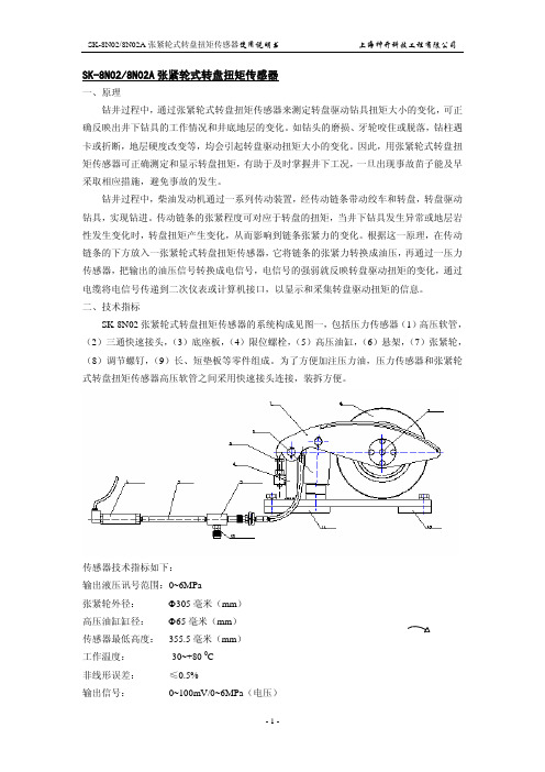
二、技术指标SK-8N02张紧轮式转盘扭矩传感器的系统构成见图一,包括压力传感器(1)高压软管,(2)三通快速接头,(3)底座板,(4)限位螺栓,(5)高压油缸,(6)悬架,(7)张紧轮,(8)调节螺钉,(9)长、短垫板等零件组成。
为了方便加注压力油,压力传感器和张紧轮式转盘扭矩传感器高压软管之间采用快速接头连接,装拆方便。
传感器技术指标如下:输出液压讯号范围:0~6MPa张紧轮外径:Φ305毫米(mm)高压油缸缸径:Φ65毫米(mm)传感器最低高度: 355.5毫米(mm)工作温度:-30~+80 0C非线形误差:≤0.5%输出信号: 0~100mV/0~6MPa(电压)或4~20mA/0~6MPa (电流)三、安装和使用 (一)引出线接线规定1. 0~100mV/0~6MPa :四线制,配有密封式YD20四芯插座2. 4~20mA/0~6MPa :二线制,配有密封式YD20三芯插座(二)安装张紧轮式转盘扭矩传感器根据钻机的不同可有两种安装方式,如下图所示,(1)封闭式链条箱的安装封闭式链条箱由于润滑、防尘的需要,其箱内有大量的润滑油,因此在安装传感器时,必须先将润滑油放尽,打开全封闭链罩,将张紧轮式转盘扭矩传感器安装在受力传动链条受力紧边,并注意传动链条方向与扭矩传感器的方向盘标识一致,并把两根限位螺栓旋到最低,其传感器高压软管与手动注油泵相连(使用快速接头),向传感器注油,张紧轮式转盘扭矩传感器会随着液压油的加注而逐渐抬起,当张紧轮轻微接触链条时,需要摆正传感器上下左右的位置,确认无误后将长、短垫板焊接在链条箱的底座上,如果焊接后发现张紧轮有偏移的现象,可以旋松底座板的四颗螺栓后,进行位置调整;也可以利用悬架两侧的调节螺钉,调节张紧轮其前后的位置,以便使链条居中。
kistler扭矩传感器说明书
kistler扭矩传感器说明书
Kistler扭矩传感器是Kistler公司生产的一种测量惯性力、旋转力
以及空间向力的传感器。
它是一种高灵敏度的、高精度的测量设备,能够
有效地提供准确的测量数据。
Kistler扭矩传感器可以测量细微的扭矩,
以及在大的负载力和高速度旋转下的转矩,使用它可以实现连续的或者瞬
时的扭矩测量。
Kistler扭矩传感器由三个部分组成:测量系统、转矩系统和传感器。
测量系统包括电源、隔离放大器、高输出电压放大器和数字转换器。
转矩
系统包括加速度计、陀螺仪、刚度计和轴承。
而传感器则有带编码器的型号、带模拟信号的型号、带双绕组的型号和带多分体的型号等。
Kistler扭矩传感器的测量方面具有优异的性能,具有路径精度高、重复精度高、噪声特性佳以及响应速度快等优点。
主要应用于回转轴系统、伺服机械系统以及矿山机械等领域。
Kistler扭矩传感器使用简便,可以根据不同的需要,它除了测量扭
矩外,还可以测量加速度、角速度、重力等。
此外,Kistler扭矩传感器
还提供网络和智能的解决方案,使用维护更加便捷,同时也更加安全可靠。
DYN-502非接触法兰盘式动态扭矩传感器说明书
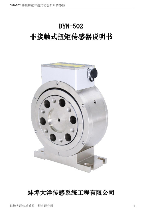
DYN-502非接触式扭矩传感器说明书蚌埠大洋传感系统工程有限公司目录1.主要功能及特点 (3)2.参数表 (3)3.产品尺寸图 (4)4.工作原理 (6)5.接线定义 (7)6.安装注意 (7)7.扭矩转换关系(防止传感器过载) (11)8.故障排除 (11)9.常见使用问题及解决方法 (12)10.安装使用参考案例 (12)11.配套仪表 (13)12.声明 (14)13.保修单说明 (14)适用于各类扭矩测试场景----推进扭矩传感器智能化无滑环动态扭矩传感器实现了1/50000以上的精度,优秀的稳定性。
微小扭矩也能实现高精度测量。
没有电刷集流环滑环等磨损件,不需要定期维护和更换零件。
传递信号时与是否旋转,转速和转向无关。
传感器直接输出扭矩信号为频率信号,配套变送器可输出电压或电流信号。
1.主要功能及特点●产品规格囊括了5~10000N.m(可定制)●无线传输无滑环高速反应●24V或±15V DC电源输入●综合精度0.2%F.S.●扭矩信号5-15kHz●合金钢材质弹性体●转速可选电流电压或频率信号●电源与信号隔离大幅降低干扰2.参数表3.产品尺寸图规格(N.m)4000-100004.工作原理通过应变仪检测对旋转转子施加的扭力,将对转子施加的扭矩量转换为电信号。
向旋转装置供电以及检测电气信号都通过非接触方式完成,旋转装置与框体之间没有机械接触部分。
框体转子5.接线定义6.安装注意6.1.测量传感器的轴径和中心高,待装。
6.2.使用两组联轴器,将传感器安装在动力设备与负载之间。
6.3.分别调整动力设备、负载、传感器的中心高和同轴度,要求小于0.05mm,然后将其固定,并紧固可靠,不允许有松动。
小量程或高转速传感器使用时,更要严格保证连接的中心高和同轴度。
否则可能造成测量误差及传感器的损坏。
6.4.传感器可选用刚性或弹性联轴器连接。
在震动较大、同轴度小于0.2mm大于0.05mm时,建议选用弹性联轴器,安装同轴度超过0.2mm时,严禁使用。
扭矩传感器系列 2000 使用说明书和数据表

Instruction manual and data sheet Torque Sensor Series 2000SENSORES E INSTRUMENTACION GUEMISA S.L.()N.I.F.: B-87969416C\ De la Fundición 4 Bis - Planta 1ºOficina-228522 Rivas Vaciamadrid (Madrid)Telf. 91 764 21 00******************Copyright ©NCTE AG® Torque Sensor Series 2000 Instruction Manual and Data Sheet. This instruction manual is property of NCTE AG®,D-82041 OberhachingUnauthorized duplication, even in part, is not permitted.State: December 2020Instruction manual1 General (5)1.1 Customer service address (5)1.2 Warranty (5)1.3 Scope of delivery (5)1.4 Declaration of conformity (6)2 Safety (7)2.1 Intended use (7)2.2 Recalibration and duration of use (7)2.3 Structural change (7)2.4 Training of the operating personnel (7)2.5 Transport and handling (7)3 Torque Sensor Series 2000 (8)3.1 Short description (8)3.2 Assembly and disassembly (8)3.3 Interface description (8)3.4 Starting up (8)3.5 Operation during regular mode (9)3.6 Irregular operation, actions in case of failures (9)3.7 Safety instructions (9)3.8 Shaft preservation (9)3.9 Service, maintenance and repair (9)3.10 Disposal (9)Data sheet1 Key Facts (10)2 Torque ranges (10)3 Load characteristics (11)4 Technical characteristics (11)5 EMV Emission data (12)6 Dimensions (13)7 Wiring diagram (14)8 Sensor wiring (14)9 Order options (14)10 Accessories (15)Instruction manual.1GeneralDear customers,Thank you for your decision to buy our sensor products. You have chosen a high quality and extremely precise torque measuring system.This manual contains all the information necessary for you and the installation, operating and maintenance personnel to use your measuring system under the intended conditions of use. It contains important information to ensure proper and safe installation and operation.For these reasons, the Instruction manual must always be available at the place of use of the torque measuring system and always ready to hand.We reserve the right to make changes in the course of product improvements. We try to maintain compatibility with previous versions. All information without guarantee subject to technical changes.For further questions, we are of course also available after the purchase at any time.Please use our contact address1.1Customer service addressNCTE AGRaiffeisenalle 3D-82041 OberhachingPhone: +49 (0)89 665 619 0Email: *************Web: https:///1.2WarrantyThe warranty period is 12 months from the date of delivery from the factory, provided that the product is used in accordance with its intended purpose, in compliance with the maintenance and calibration regulations and the General Terms and Conditions of Business.You can find these, current instruction manuals and data sheets on:https:///en/standard-products/#1.3Scope of deliveryThe torque sensor system consists of a calibrated sensor, signal acquisition / -processing integrated in the housing, a 5 m long connection cable with plug (Binder plug no. 99-0426-10-08) and keystone (round shaft) or square sleeve (square shaft).Enclosed you will find the corresponding calibration certificate and the warning notes.1.4Declaration of conformityThe manufacturerNCTE AGRaiffeisenalle 3D-82041 Oberhachinghereby declares that the following productProduct designation: Torque sensor series 2000Trade designation: Series 2000Model names: 2100-2.5 2200-2.52100-5 2200-52100-7.5 2200-7.52100-15 2200-17.52100-60 2200-752100-140 2200-1752200-2502100-400 2200-500conforms to the requirements of the EMC Directive 2014/30/EU – including its amendments in force at the time of this declaration.The following harmonized standards were applied:EN 61000-6-2:2019-11EN 61000-6-4:2020-09EN 61326-1:2013-07EN 61326-1:2018-09 (Draft)The following national laws, standards and specifications were applied:Electromagnetic compatibility law – EMVGPlace: OberhachingDate: December 15th 2020______________________________ ______________________________Dr. Jürgen Uebbing, CEO Ms. Verena Graf, COO______________________________Mr. Bernhard Mayr, Technical Director2SafetyPlease note the enclosed sheet on the warning notes.2.1Intended useThe sensors of the series 2000 are designed exclusively for measuring torque and/or speed. The respective load range can be taken from the data sheet and must not be exceeded.Proper use also includes compliance with the commissioning, assembly, operating, ambient and maintenance conditions specified by the manufacturer.Any use beyond these is considered improper. The manufacturer is not liable for any damage resulting from such use.2.2Recalibration and duration of useA factory recalibration should be executed annually. See the corresponding label on the sensor.This recalibration can be carried out quickly and easily by NCTE AG.Please contact us.If the sensor is used within the limits of its intended use and regularly calibrated, the sensor's operating life is unlimited.2.3Structural changeUnauthorized conversions or changes to the torque measuring system are prohibited for safety reasons and lead to the immediate expiration of the warranty claims.2.4Training of the operating personnelAssembly, commissioning and maintenance personnel must have read and understood the complete operating instructions, especially Chapter “2 Safety". The operator is recommended to have this confirmed in writing.2.5Transport and handlingDuring handling, storage and transport, make sure that the sensor is not exposed to strong magnetic or electromagnetic fields (e.g. degaussing coils).3Torque Sensor Series 2000The Series 2000 provides the easiest and most cost-effective entry into torque measurement technology.3.1Short descriptionThe series is mainly used in test stands, automation processes, production lines e.g. end-of-line tests and teaching.Torque measurement is possible both statically and dynamically. The mechanical connection is made via a square shaft (series 2100) or round shaft (series 2200).The Series 2000 provides an analogue output signal with 0-5V.The sensor is delivered as a ready-to-connect unit including 5m cable, keystones (round shaft) and calibration certificate.3.2Assembly and disassemblyWhen mounting the sensor, make sure that the measuring shaft is exactly aligned with the connecting shafts (corresponding couplings can be found in the accessories). It must then be possible to push the key adapters / square ends of the connection shafts onto the key adapter connections / square connections of the sensor without any effort. No force must be exerted on the housing in the axial direction during fastening. The sensor can be secured against rotation by means of the flat surface (optional sensor holder). The cable length must not exceed 5m. Using a cable other than the one supplied by NCTE or an identical cable with a different cable length may impair the function of the sensor system.The disassembly may only be done without applying torque to the measuring shaft.3.3Interface descriptionMechanical interfaces:For power transmission, adapter connections are provided at both ends of the keystone round shafts. In respect to square sensors, the shaft has square ends.Electrical interface:A socket for power supply and signal output is attached to the upper side of the housing.(Pin assignment see Chapter “7 Wiring diagram")3.4Starting upAfter mounting the sensor, the following must be observed:∙Switch on power supply and check voltage value.(Voltage peaks at the sensor must be avoided, devices must be checked accordingly beforeconnection to the sensor)∙Connect the sensor to the power supply. (using the cable supplied).∙Record the output signal of the sensor with high resistance.(e.g. A/D converter, oscilloscope, PC measuring card)∙Record output signal in mechanically unloaded state of the sensor.3.5Operation during regular modeOptimal measuring values are achieved when the sensor is used while maintaining the specific nominal torque. If the permissible operating conditions are observed, the sensor operates trouble-free and maintenance-free.3.6Irregular operation, actions in case of failuresIf the sensor is mechanically overloaded (e.g. if the maximum permissible longitudinal force or torque limit is exceeded or if there are strong vibrations), the sensor may be damaged and the signal output may be distorted. In this case do not open the device. Contact NCTE AG directly.3.7Safety instructionsThe following safety instructions should be followed for smooth operation:∙Opening the sensor or even single screws is not allowed.∙The shaft retaining rings on the shaft ends must not be loosened.∙The fastening nut of the plug must not be loosened or tightened.∙Only use power supplies safely disconnected from the mains voltage.∙Regarding the electrical and mechanical load of the sensor, the specifications according to the sensor-specific nameplate and the table in Chapter “4 Technical characteristics” must be observed.∙The sensor is not to be used as support bearing. The existing fastening options serve exclusively to secure the housing against twisting.∙To protect your system, we recommend increasing the torque over several stages.3.8Shaft preservationThe shafts are protected on both sides with a film of anti-corrosion wax. We recommend to leave the protection permanently. If technically necessary, remove the protective film with spirit/ethanol.3.9Service, maintenance and repairAs part of your test and measurement equipment management, we recommend regular inspection of your test and measurement equipment. Please also observe the relevant standards and guidelines. Maintenance plan by NCTE AGCalibration: Every 12 monthsCheck the wiring, connectors and shaft: Every 12 monthsRepairs and recalibrations can only be carried out by NCTE AG personnel.3.10DisposalThe device must be returned to NCTE AG, Raiffeisenallee 3, D-82041 Oberhaching for disposal.Data sheet. 1Key Facts2Torque rangesNote: Series 2100 sensor versions are calibrated to nominal torque. However, the absolute operating limits are as shown in the table above. Do not exceed the specified magnitude of the limit torques for unidirectional and bidirectional loading.Note: In case of overload, the sensor leads to a measurement offset. In this case the sensor must be recalibrated at NCTE AG. The sensor may only be operated within the specified nominal torque range.3Load characteristicsAny irregular stress (bending moment, transverse or axial force, exceeding the nominal torque) up to the specified static load limit is only permissible as long as none of the other stresses can occur. Otherwise the limit values must be reduced. If 30 % of the limit bending moment and 30 % of the limit transverse force are present in each case, only 40 % of the axial force is permissible, whereby the nominal torque must not be exceeded.4Technical characteristics1 Specified values only apply to direct axial force on the shaft. If the axial force acts on the circlip, only 50 % of the force is permissible.2 Specified values only apply to direct axial force on the shaft. If the axial force acts on the circlip, only 50 % of the force is permissible.3The accuracy class means that the linearity deviation as well as the circulation modulation, individually, are each less than or equal to the value specified as the accuracy class. The accuracy class must not be confused with a classification according to DIN 51309 or EA-10/14.4 %ME: Related to the measuring range.5 The exact sensor-specific values can be found in the calibration certificate supplied.EMV immunity and emitted interference (DIN EN IEC 61000-6-2 / DIN EN IEC 61000-6-4 / DIN EN 61326-1)6 Wiring connected.6 DimensionsSeries 2200For high alternating loads, torque transmission by positive and frictional locking via a suitable fit or couplingis recommended.2200 (TM-HR-Rd)Round drive2100 (TM-HR-Sq)Square drivePotentiometer for offset adjustmentKeystone7 Wiring diagramConnectorPower supply and outputs8 Sensor wiringThe grey and blue wires are not required.The blue wire is not required.9 Order optionsWe would be pleased to provide you with further information about serial products in a personal contact underPhone: +49 (0)89 66 56 19 30 or by e-mail: *************.10AccessoriesBracket1 2.5 – 17.5 Nm (Art. No.: 400006081)2 75 – 250 Nm (Art. No.: 400006082)Readout unit1 Order number 400010-ATS001 The NCTE readout unit is a multifunctional readout unit fora USB interface.Couplingscoupling types Used for D2 max.You can obtain further or additional accessories and special requests in a personal discussion with your contact person for series products by calling +49 (0)89 66 56 19 30 or by e-mail: *************.Your experts for magnetostrictive sensorsSENSORES E INSTRUMENTACION GUEMISA S.L.C\ La Fundición 4 Bis - P 1Oficina-2l ª28522 Rivas Vaciamadrid (Madrid)Telf. 91 764 21 00 email:******************。
CYB-803S扭矩传感器使用说明书

HX-901型扭矩传感器三河燕郊华欣机电有限公司HX-901扭矩传感器使用说明书一、前言:本系列扭矩传感器是在标准测扭应变传感器的基础上研制开发的专门传递扭矩参数的传感器。
本系列扭矩传感器可以传递静止扭矩信号、旋转扭矩信号、动态扭矩信号、静态扭矩信号,传递信号时与是否旋转,转速和转向无关。
本系列扭矩传感器的能源及信号的传递都采用了非接触的方式,因此本产品可以适应长时间,高转速运转。
二、特点:1. 既可以传递静止扭矩信号,也可以传递旋转转矩信号;2. 既可以传递静态扭矩信号,也可以传递动态扭矩信号;3. 精度高,稳定性好;4. 体积小,重量轻,易于安装;5. 不需反复调零即可连续传递正反转扭矩信号;6. 没有集流环等磨损件,可以高转速长时间运行;7. 抗干扰性强;8. 可任意位置,任意方向安装;三、HX901系列扭矩传感器应用范围1. 传递电动机、内燃机等旋转动力设备的输出扭矩及功率。
2. 传递发电机、风机、泵、搅拌机、减速器、变速器、卷扬机、螺旋桨、钻探机械等设备的负载扭矩及输入功率。
3. 传递各种机械加工中心、自动机床工作过程中的扭矩。
4. 传递各种旋转动力设备系统所产生的扭矩及效率。
5.可用于制造粘度计。
四、HX901扭矩传感器技术指标1.工作范围:5N·m-30万N·m(大量程可以定做)2.精度:0.5%(F·S)3.环境温度:0℃-50℃4.频率响应:100 μs5.输出信号: 零扭矩: 10 KHZ正向满量程: 15 KHZ 反向满量程:5 KHZ8.输出电平:0-12v 负载电流<10mA9.信号插座: (1)0V. (2)+15V. (3)-15V. (4)转速信号.(5)扭矩信号.五、HX901扭矩信号耦合器工作原理本系列扭矩信号耦合器的电源供应由设在标准应变桥扭矩传感器上的一组环型变压器提供的感应电压经过轴上整流,稳压电路变换成高稳定性的直流电压。
GB-DTS系列扭矩传感器说明书
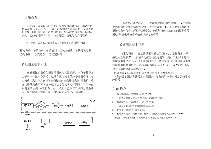
开箱后,请先按《装箱单》所列项目认真清点,确认箱内 物品是否与《装箱单》一 致,查看物品在运输过程中是否有破 损现象,同时核对发货产品的铭牌,确认产品的型号、规格及 参数与您的订货要求一致。如有问题,请速与我公司联系。
注:特殊订做产品,箱内物品以《装箱单》所列物件为准。
箱内物品:①装箱单 ②传感器 ③航空插头 ④使用说明书 ⑤合格证 ⑥变送器 ⑦检定报告
0-10;30; 18 85 8 50 122 31 61 100 50 108 186
50;100
200
28 92 8 72 123 41 61 100 56 125 208
500
38 106 8 72 127 55 61 108 66 136 238
1K
48 113 8 69 125 70 78 120 68 158 273
注:仪表使用请详细阅读数字式测量仪部分。
附图
♦ 联机的测试电缆线应妥善固定好,防止旋转系统将其绞断。 ♦ 测试电缆线的航空插头处的屏蔽线接点不应随意拆除。 ♦ 测试电缆线的航空插头与传感器及仪表的航空插座应拧紧可 靠。
未选用二次仪表时的使用方法
特别注意
♦ 为了避免触电,应使用三芯电源线与三线式电源插座联接进 行供电,三线式电源插座的中心地线必须可靠接地。
检查运行系统电参数
检查运行系统中的动力系统电压、传感器的供电电压是否在额 定值范围内。
定期保养、维护
用户根据使用要求、环境,可以半年或壹年对传感器进行一次 定期检查。 检查项目除日常保养、维护的内容外,还应对轴承清洗、加注
润滑油。
只有受过专业培训的人才能拆卸部件后进行维护及器件 更换。
9
10
30K 140 220 4-M12 88 146 150 193 240 140.2 281 452
- 1、下载文档前请自行甄别文档内容的完整性,平台不提供额外的编辑、内容补充、找答案等附加服务。
- 2、"仅部分预览"的文档,不可在线预览部分如存在完整性等问题,可反馈申请退款(可完整预览的文档不适用该条件!)。
- 3、如文档侵犯您的权益,请联系客服反馈,我们会尽快为您处理(人工客服工作时间:9:00-18:30)。
GB-DTS盘式扭矩传感器说明书
本系列扭矩传感器具备:
1.扭矩测量功能;.
2.可以传递静止扭矩信号、旋转扭矩信号。
3.传递信号时与是否旋转,转速和转向无关。
4.静止外壳和旋转盘之间无轴承,可以适应长时间,高转速运转。
5.精度高,稳定性好;5体积小,重量轻,易于安装;
6.不需反复调零即可连续传递正反转扭矩信号;
7.没有集流环等磨损件,可以高转速长时间运行;
8.抗干扰性强;
9.可任意位置,任意方向安装;
1. 信号输出波形方波幅度可选5V/12V。
2. 开机5分钟即可进入工作状态,勿需预热过程。
3. 检测精度高、稳定性好、抗干扰性强。
4. 不需反复调零即可连续测量正反扭矩。
5. 体积小、重量轻、易于安装。
6. 传感器可脱离二次仪表独立使用,只要按插座针号提供±15V(200mA)的电源,即可输出阻抗与扭矩成正比的等方波或脉冲波频率信号。
五、产品系列:
GB-DTS-P盘式扭矩传感器外型尺寸如下图:
六、主要性能及电气指标:
扭矩精度:<±0.5 % F· S、<±0.3 % F· S、<±0.1 % F· S(可选)
频率响应:100μs
非线性:<±0.2 % F· S
重复性:<±0.1% F· S
回差:<0.1 % F· S
零点时漂:<0.2 % F· S
零点温漂:<0.2 % F· S /10℃
输出阻抗:350Ω±1Ω、700Ω±3Ω、1000Ω±3Ω(可选)
绝缘阻抗:>500MΩ
静态超载: 120 % 150% 200%(可选)
使用温度:-10 ~ 50℃
储存温度:-20 ~ 70℃
电源电压: ±15V±5%
总消耗电流:<200mA
频率信号输出: 5KHZ—15KHZ
额定扭矩: 10KHZ±5kHZ (正反双向测量值)
信号占空比:(50±10)%
七、信号输出与信号采集:
1、扭矩信号输出基本形式:
•方波信号、脉冲信号。
•可根据用户需要制成电压模拟信号输出或电流模拟信号输出(单向、静止扭矩测量)。
2、扭矩信号处理形式:
•扭矩传感器输出的频率信号送到频率计或数字表,直接读取与扭矩成正比的频率信号或电压、电流信号。
•扭矩传感器的扭矩与频率信号送给单片机二次仪表,直接显示实时扭矩值、转速及输出功率值及 RS232通讯信号。
•直接将扭矩与转速的频率信号送给计算机或 PLD进行处理。
八、维护与保养:
1.每隔一年应给扭矩传感器两端轴承加润滑脂。
加润滑脂时,仅将两端轴承盖打开,将润滑脂加入轴承,然后装上两端盖。
2.应储存在干燥、无腐蚀、室温为 -20℃——70℃的环境里。
九、注意事项:
1.安装时,不能带电操作,切莫直接敲打、碰撞传感器。
2.联轴器的紧固螺栓应拧紧 ,联轴器的外面应加防护罩,避免人身伤害。
3.信号线输出不得对地 ,对电源短路,输出电流不大于10mA•屏蔽电缆线的屏蔽层必须与 +15V电源的公共端(电源地)连接。
十、电气连接:
如图10所示,扭矩传感器用一个航空接头(X12K5P)与外部设备连接,
插座端固定在机壳上。
航空插座管脚定义如下图:
安装
1. GB-DTS-P盘式扭矩传感器型转速传感器由静止外壳和旋转盘两部分组成.
2.将静止外壳套在旋转盘的外侧.两端对齐。
3.将旋转盘的两端通过法兰联轴器分别与动力或负载联接.
4.静止外壳固定在基座上,调整间隙,保证静止外壳与旋转柱之间不可
接触!。