Huck-fasteners-catalog_Byler Rivet
Huck International, Inc. 257系列工具说明书

07-28-2006I NSTRUCTION M ANUAL257P NEUDRAULIC I NSTALLATION T OOL___________________________________Henk RosierEngineering Manager,Installation Systems DivisionKingston, New York, USAAugust, 1998Huck Model 256 Vibration Level The sound level of the 256 tool cycling without fastener isC ONTENTSEU D ECLARATION OF CONFORMITY . . . . . . . . . . . . . . . . . . . . . . . . . . . . .2 S AFETY . . . . . . . . . . . . . . . . . . . . . . . . . . . . . . . . . . . . . . . . . . . . . . . . . . .4 S PECIFICATIONS . . . . . . . . . . . . . . . . . . . . . . . . . . . . . . . . . . . . . . . . . . . . .5 P RINCIPLE OF OPERATION . . . . . . . . . . . . . . . . . . . . . . . . . . . . . . . . . . . . .6 P REPARATION FOR U SE . . . . . . . . . . . . . . . . . . . . . . . . . . . . . . . . . . . . . .7 S ERVICING THE TOOLGeneral . . . . . . . . . . . . . . . . . . . . . . . . . . . . . . . . . . . . . . . . . . . . . .7Daily . . . . . . . . . . . . . . . . . . . . . . . . . . . . . . . . . . . . . . . . . . . . . . . . .7Weekly . . . . . . . . . . . . . . . . . . . . . . . . . . . . . . . . . . . . . . . . . . . . . . .7Disassembly . . . . . . . . . . . . . . . . . . . . . . . . . . . . . . . . . . . . . . . . .8-9Assembly . . . . . . . . . . . . . . . . . . . . . . . . . . . . . . . . . . . . . . . . .10-11Fill and Bleed . . . . . . . . . . . . . . . . . . . . . . . . . . . . . . . . . . . . . .11-12Assembly Drawing . . . . . . . . . . . . . . . . . . . . . . . . . . . . . . . . . . . . .13Parts List . . . . . . . . . . . . . . . . . . . . . . . . . . . . . . . . . . . . . . . . . . . .14 T ROUBLESHOOTING . . . . . . . . . . . . . . . . . . . . . . . . . . . . . . . . . . . . . . . . .15A CCESSORIES . . . . . . . . . . . . . . . . . . . . . . . . . . . . . . . . . . . . . . . . . . . . .15S ERVICE N OTES . . . . . . . . . . . . . . . . . . . . . . . . . . . . . . . . . . . . . . . . . . .165When the trigger is depressed, the throttle valve moves to down position, and pressurized air is directed to the bottom of the air piston, causing the piston to move upward. The air above the piston is exhausted and directed through the center of the throttle valve and out the bottom of the tool. The air piston has a rod and a hydraulic piston attached. When the air piston rod moves upward, a column of pressurized fluid is forced into head, which moves the pull piston back. The attached nose assembly moves with the pull piston to start fastener installation.When fastener installation is completed, the trigger is released. Air pressure, with the assistance of a spring, causes the throttle valve to return to its up position. Pressurized air is re-directed to the top of the air piston, causing the piston to move downward. The air from below the piston is exhausted through bottom of tool. The rod and hydraulic piston move downward, hydraulic pressure is reversed and the pull piston is returned forward. Return pressure relief valve protects tool against pressure spikes. The reservoir replenishes hydraulic system as needed.6The Model 257 Installation Tool is shipped with a plastic plug in the air inlet connector. The connector has 1/4-18 female pipe threads to accept the air hose fitting. Quick disconnect fittings and 1/4” inside diameter air hose are recommended. An air supply of 90-100 psi capable of 20 CFM must be available. Air supply should be equipped witha filter-regulator-lubricator unit.1.Remove plastic shipping plug from Air Inlet Connectorand put in a few drops of Automatic Transmission Fluid, DEXRON III, or equivalent.2.Screw quick disconnect fitting into Air Inlet Connector.CAUTION: Do not use TEFLON tape on threads - - use TEFLON in stick form only. (Huck P/N 503273)3.Set air pressure on regulator to 90-100 psi.4.Attach optional Air Hose (38), supplied with tool, to airinlet connector.5.Connect air hose to tool.6.Cycle tool a few times by depressing and releasingtrigger.7.Disconnect air hose from tool.8.Remove Retaining Nut and Stop.9.Select proper Nose Assembly from SELECTIONCHART for fastener to be installed.10.Screw Collet Assembly (including lock collar and shimif applicable) onto Spindle holding Pull Piston (11) with 3/8 hex key. (Wrench Tight)11.Slide Anvil over Collet Assembly and into counterbore.12.Slide Stop and Retaining Nut over Anvil and screw Nutonto Head.13.Connect air hose to tool and install fastener(s) in testplate of proper thickness with proper size holes.Inspect fastener(s).NOTES:1 Air quick disconnect fittings and air hoses are notavailable from Huck International, Inc.2 VIBRA-TITE should be used on collet threads for noseassemblies without lock collars. All other noses should be staked (please refer to nose assembly data sheets).P REPARATION FOR U SEG ENERAL1. The efficiency and life of any tool depends upon propermaintenance. Regular inspection and correction of minor problems will keep tool operating efficiently and prevent downtime. The tool should be serviced by personnel who are thoroughly familiar with how it operates.2.A clean, well-lighted area should be available forservicing the tool. Special care must be taken to prevent contamination of pneumatic and hydraulic systems.3. Proper hand tools, both standard and special, must beavailable.4. All parts must be handled carefully and examined fordamage or wear. Always replace Seals, when tool is disassembled for any reason. Components should be disassembled and assembled in a straight line without bending, cocking, or undue force. Disassembly and assembly procedures outlined in this manual should be followed.5. Service Parts Kit 257KIT includes consumable partsand should be available at all times. Other components, as experiece dictates, should also be available.D AILY1. If a Filter-Regulator-Lubricator unit is not being used,uncouple air disconnects and put a few drops of Automatic Transmission Fluid or light oil into the air inlet of the tool. If the tool is in continuous use, put a few drops of oil in every two to three hours.2. Bleed the air line to clear it of accumulated dirt or waterbefore connecting air hose to the tool.3. Check all hoses and couplings for damage or air leaks,tighten or replace if necessary.4. Check the tool for damage or air/hydraulic leaks,tighten or replace if necessary.5. Check the nose assembly for tightness or damage,tighten or replace if necessary.6. Check oil level in tool reservoir, replenish if necessary. W EEKLY1. Disassemble and clean nose assemblies andreassemble per applicable NOSE ASSEMBLY DATA SHEET.2. Check the tool and all connecting parts for damage oroil/air leaks, tighten or replace if necessary.S ERVICING THE TOOL !M ODEL257 A SSEMBLY I NSTRUCTIONSStep 6Connect tool to shop air regulated to 20 to 40 psi. Cycle tool 20-30 times. Watch for air bubbles escaping from the tool into bottle. (You may rock the tool to free trapped air in the tool.) Do not allow the air to re-enter the tool.Step 7When air bubbles no longer appear in bottle, remove fill bottle while tool is lying on its side.Step 8Install the check valve Ball (77), Guide (76) and Spring (75). Replace the Plug (71). (Fig. 7)Note:When cycling tool, always hold bottle up as shown Step 9Turn tool so front of head faces you and remove the relief valve Plug (83). Prior to removing Plug (83), it is advisable to back out setscrew inside of plug by approximately 1/2turn counterclockwise. (See Figure 7a). This ensures that the Piston will remain in full-forward position. Install relief valve Ball (87), Guide (86), Sleeve (85) and Spring (84).Replace the Plug (83).Step 10Unlock Fill Tool and check Reservoir red line. At this point cycle tool with Stall Nut attached (Optional. See note)and retaining nut locked in the full forward position (“Dead Stall”). Reservoir should not drop below the red line on the reservoir housing.NOTE:Dead Stalling is not necessary if Optional Stall nut was not used; just cycle tool.Step 11Re-lock the fill tool in out position .Lay tool on its left side and remove Bleed Plug (64). Top off reservoir by placing a few drops of oil in hole and wait for air bubbles to escape. Push a pin or a scribe into hole to check for trapped air bubbles. Replace plug. (Fig. 7)!A SSEMBLY D RAWINGAlways check out the simplest possible cause of a malfunction first. For example, an air hose not connected. Then proceed logically, eliminating each possible cause until the cause is located. Where possible, substitute known good parts for suspected bad parts. Use TROUBLESHOOTING CHART as an aid in locating and correcting malfunction.NOTE:“Piston drift” is when the air piston is in the down position, but the hydraulic pull piston is not in the full follward position. This causes an out of sequence condition.1 Tool fails to operate when trigger is depressed.a) Air line not connectedb)Throttle Valve O-rings (37 & 39) worn ordamaged.c)Throttle Valve Cable (2) is broken.2 T ool does not complete fastener installation andbreak pintail.a)Air pressure too lowb)Air Piston Quad ring (50) worn or damaged.c) Reservoir empty or low, refer to Fill and Bleedsection.d) Air in hydraulic system, refer to Fill and Bleedsection.e) Reservoir Springs (82) worn or damagedf) Check for piston drift3 Pintail stripped and/or swaged collar not ejected.a) Check for broken or worn jaws in nose assembly,refer to nose assembly data sheet.b) Check for loose Retaining Nut (8)c)Check for piston drift.4Tool has piston drift.a) Loose collet crashing into the front of the anvilcauses the relief valve to open allowing thepiston to drift. Tighten the collet and refer to Filland Bleed section.b) Worn or damaged Return Pressure Relief Valvein tool, inspect Seat (88), O-ring (72), Back-upRings (25), Steel Ball (87) and Valve Spring (84).Replace if necessary.c) Worn or damaged Piston Assembly (31): InspectO-ring (33), O-ring (35) and Back-up Rings (93).Replace if necessary.5Hydraulic fluid exhausts with air or leaks at base of handle.a) Worn or damaged Gland Assembly (54), inspectVariseal (61), O-rings (55, 56 & 58), Quad-ring(48) and Back-up Ring (57). Replace if necessary.6.Hydraulic fluid leaks at rear of Pull Piston (11)a) Worn or damaged Rear Gland (94): InspectO-rings (16 & 18) and Back-up Rings (17 & 19).Replace if necessary.7.Hydraulic fluid leaks at front of Pull Piston (11).a) Worn or damaged Front Gland : Inspect Polyseal(10). Replace if necessary.8. Pull Piston (11) will not return.a) Throttle Valve (36) stuck: Lubricate O-rings (37 &(39).b) Throttle Arm (66), Cable (2) or Trigger (3) binding.9. Air leaks at air Cylinder Head (49).a). Worn or damaged O-ring (48). Replace ifnecessary.A CCESSORIESStall Nut (Fig. 7)-120824Service Tool Kit-126104Includes:Assembly Bullet (Fig. 2) -123111-1Spacer (Fig. 2)-123112-1Pintail Collection Bag-125655T ROUBLESHOOTINGS ERVICE N OTES:L IMITED W ARRANTIESAmericasAlcoa Fastening SystemsAerospace Products Tucson Operations 3724 East Columbia Tucson,AZ 85714800-234-4825520-747-9898FAX:520-748-2142Alcoa Fastening SystemsAerospace Products Carson Operations PO Box 5268900 Watson Center Rd.Carson,CA 90749800-421-1459310-830-8200FAX:310-830-1436Alcoa Fastening SystemsCommercial Products Waco Operations PO Box 81178001 Imperial Drive Waco,TX 76714-8117800-388-4825254-776-2000FAX:254-751-5259Alcoa Fastening SystemsCommercial Products Kingston Operations 1 Corporate Drive Kingston,NY 12401800-431-3091845-331-7300FAX:Alcoa Fastening SystemsCommercial Products Canada Operations6150 Kennedy Road,Unit 10Mississagua,Ontario L5T2J4Canada905-564-4825FAX:905-564-1963Alcoa Fastening SystemsCommercial Products Latin America Operations Avenida Parque Lira.79-402Tacubaya Mexico,D.F.C.P .11850FAX:525-515-1776TELEX:1173530 LUKSMEFar EastAlcoa Fastening SystemsCommercial Products Australia Operations 14 Viewtech Place Rowville,Victoria Australia 317803-764-5500Toll Free:008-335-030FAX:03-764-5510EuropeAlcoa Fastening SystemsCommercial ProductsUnited Kingdom Operations Unit C,Stafford Park 7Telford,Shropshire England TF3 3BQ 01952-290011FAX:0952-290459Alcoa Fastening SystemsAerospace Products France Operations Clos D’Asseville BP495450 Us Par Vigny France33-1-30-27-9500FAX:33-1-34-66-0600A Global OrganizationAlcoa Fastening Systems (AFS) maintains company offices throughout the United States and Canada,with subsidiary offices in many other countries.Authorized AFS distributors are also located in many of the world’sindustrial and Aerspace centers,where they provide a ready source of AFS fasteners,installation tools,tool parts,and application assistance.For The Long Haul,The Future of Fastening Technology,The Future of Assembly Technology,The Future of ToolingTechnology,and Tools of Productivity are service marks of Huck International.Huck provides technical assistance regarding the use and application of Huck fasteners and tooling.NOTICE:The information contained in this publication is only for general guidance with regard to properties of the products shownand/or the means for selecting such products,and is not intended to create any warranty,express,implied,or statutory;all warranties are contained only in Huck’s written quotations,acknowledgements,and/or purchase orders.It is recommended that the user secure specific,up-to-date data and information regarding each application and/or use of such products.HWB898 1003-5M© 2003 Alcoa Fastening SystemsAlcoa Fastening Systems world-wide locations:One Great ConnectionSM。
海洋工具商杰克逊锐锐涂层棒说明书

1. Study, understand, and follow all instructionsbefore operating this device.2. Do not exceed rated capacity.3. Use only on hard, level surfaces.4. Lifting device only. Immediately after lifting,support the vehicle with appropriate means.5. Do not move or dolly the vehicle while on the jack.6. Failure to heed these markings may result inpersonal injury and/or property damage.7. Lift only areas of the vehicle as specifiedby the vehicle manufacturer.8. No alterations shall be made to this product.9. Never work on, under or around a loadsupported only by this device.10. Do not adjust safety valve.11. Wear ANSI-approved safety goggles andheavy-duty work gloves during use. 12. Keep clear of load while lifting and lowering.13. Lower load slowly.14. Apply parking brake and chock tiresbefore lifting vehicle.15. Lift vehicle only at manufacturerrecommended locations.16. Inspect before every use; do not use if parts areloose or damaged, or if leaking hydraulic fluid.17. Do not use for aircraft purposes.18. Do not use any objects (such as blocks of wood) inbetween Saddle Pad or Saddle and lifting point.Objects placed on the Saddle will reducethe stability of the Jack, and could allow thevehicle to slip off the Saddle and fall.19. The warnings, precautions, and instructionsdiscussed in this manual cannot cover allpossible conditions and situations that may occur.The operator must understand that common senseand caution are factors, which cannot be built intothis product, but must be supplied by the operator. 20. The Handle socket may be held down by a clip undertension. Wear ANSI-approved safety goggles before freeing Handle socket. Remove clip carefully.SAVE THESE INSTRUCTIONS.IMPORTANT! Before first use:Check hydraulic oil level and fill as needed as stated on page 6. Thoroughly test the Jack for properoperation. If it does not work properly, bleed air from its hydraulic system as stated on page 6.Page 2For technical questions, please call 1-888-866-5797.Item 64784Item 64784Page 3For technical questions, please call 1-888-866-5797.Page 4For technical questions, please call 1-888-866-5797.Item 64784SaddleHandleFoam Bumper HandleSocketHandleRelease Bolt(not shown) Lift ArmPage 5 For technical questions, please call 1-888-866-5797.Item 64784Page 6For technical questions, please call 1-888-866-5797.Item 64784Read the ENTIRE IMPORTANT SAFETY INFORMATION section at the beginning of this manual including all text under subheadings therein before set up or use of this product.Removing Shipping ClipCAUTION! The Handle socket may be held down by a clip under tension. Wear ANSI-approved safety goggles before freeing Handle socket. Remove clip carefully.A wire clip holds the Handle Socket in position during shipment. This helps prevents shipping damage. To remove it:1. Press down on the Handle Socket torelieve tension on the wire clip.2. Disconnect the wire clip legs from the bar.3. Slowly raise the Handle Socketuntil tension is released.4. Remove the wire clip.Attaching the Handle1. Slide the Upper Handle into the Lower Handle.Line the Button on the Lower Handle up with the hole in the Upper Handle until it clicks into place.2. Loosen the Handle Release Bolt and insert thegrooved end of the Handle into the Handle Socket.3. Tighten the Handle Release Bolt. Gently pull upon the Handle to make sure that it is secure.Bleeding Trapped Air1. With the Jack fully lowered, remove both Screwson the end of the Cover Plate that is closer to the Saddle. Swing Cover Plate open. See Figure A.2. Remove the Fill Plug on top of the Cylinder.Check that the oil level inside the Cylinder just covers the top of the Piston. See Figure B.3. Turn the Handle counterclockwise to open the valve.4. Pump the Handle up and down quickly10-15 times to force air from the system.5. Replace the Fill Plug, close theCover Plate, and reinstall the Screws.Fill PlugSafety Valve Covers Do not open or adjust.Figure A: Hydraulic UnitAdding OilNOTICE: To prevent damage and premature wear, use only non-detergent 22 weight hydraulic jack oil.1. With the Jack fully lowered, remove both Screwson the end of the Cover Plate that is closer to the Saddle. Swing the Cover Plate open.2. Remove the Fill Plug on top of the Cylinder.3. Add non-detergent 22 weight hydraulic jack oilinto the Fill Plug hole slowly until the oil level just covers the top of the Piston inside the Cylinder.4. Replace the Fill Plug, close theCover Plate, and reinstall the Screws.Figure B: Fill LevelRead the ENTIRE IMPORTANT SAFETY INFORMATION section at the beginning of thismanual including all text under subheadings therein before set up or use of this product. LiftingPark vehicle on a flat, level, solid, surface safely away from oncoming traffic. Turn off the vehicle’s engine. Place the vehicle’s transmission in “PARK” (if automatic) or in its lowest gear (if manual).Set the vehicle’s emergency brake. Then, chock the wheels that are not being lifted.1. Turn the Handle counterclockwise to lower the Jack.Once the Jack is fully lowered, turn theHandle firmly clockwise to close it.2. Carefully position the Saddle of the Jack under thevehicle manufacturer’s recommended lifting point.(See vehicle manufacturer’s owner’s manualfor location of frame lifting point.)3. Pump the Handle until the top of the Jack’s Saddlehas nearly reached the vehicle lifting point. Positionthe Saddle directly under the vehicle’s lifting point. 4. To lift the vehicle, pump the Handle.Use smooth, full strokes.5. Once the vehicle is raised, slide a jack stand ofappropriate capacity (not included) under a properlifting point referred to in the vehicle owner’smanual. Always use two jack stands, position themat the same point on each side of the vehicle.WARNING! The rated capacity of jack stands is per pair, not the individual capacities combined unless specifically noted on the product by the jack stand manufacturer. Do not exceed rated jack stand capacity. Ensure that the vehicle support points are fully seatedin the saddle of both jack stands. Use a matched pairof jack stands per vehicle to support one end only. Failure to do so may result in the load suddenly falling, which may cause personal injury and/or property damage.6. Center saddle of the jack stand(s) under the vehicle’slifting point(s). Set the jack stand(s) to the sameheight according to the manufacturer’s instructions,making sure that they lock securely into position.7. Slowly turn the Handle counterclockwise to lowerthe vehicle onto the saddle(s) of the jack stand(s).Then, turn the Handle firmly clockwise to close it.Lowering1. Carefully remove all tools, parts, etc.from under the vehicle.2. Position the Saddle under the lifting point.Turn the Handle firmly clockwise and raise load high enough to clear the jack stands,then carefully remove jack stands.3. Slowly turn the Handle counterclockwise(never more than 1/2 full turn) to lowerthe vehicle onto the ground.4. Lower the Jack completely. Then, store in asafe, dry location out of reach of children.Page 7For technical questions, please call 1-888-866-5797. Item 64784Procedures not specifically explained in this manual mustbe performed only by a qualified technician.TO PREVENT SERIOUS INJURY FROM TOOL FAILURE: Do not use damaged equipment. If abnormal noise or vibration occurs, have the problem corrected before further use.1. BEFORE EACH USE, inspect the generalcondition of the tool. Check for:• leaking hydraulic oil,• loose hardware or parts,• misalignment or binding of moving parts,• cracked, bent or broken parts, and• any other condition that mayaffect its safe operation.Thoroughly investigate and correct the causes for all issues that are found. Do not use Jack until all issues are understood and properly corrected.ALSO, BEFORE EACH USE, thoroughly testthe Jack for proper operation prior to actual use.If the Jack’s motion seems spongy or theSaddle does not lift completely, followBleeding instructions on page 6.2. AFTER USE, wipe dry with a clean cloth. Then,store the Jack in a safe, dry location out of reachof children and other non-authorized people. NOTICE: Storing the Jack in a humid area orexposing it to corrosive vapor voids the warranty.3. Weekly - Jack Lubrication:a. Lubricate according to the below steps usingonly general purpose lithium grease.b. Inject grease into each of the grease fittings.c. Lubricate the linkages and pivot points lightly. Note: Improper or inadequatelubrication voids the warranty.4. Change the hydraulic oil at leastonce every three years:a. With the Jack fully lowered, remove both Screwson the end of the Cover Plate that is closer tothe Saddle. Swing the Cover Plate open.b. Remove the Fill Plug on the top of the Cylinder.c. Tip the Jack to allow the old hydraulic oilto drain out of the Housing completely,and dispose of the old hydraulic oil inaccordance with local regulations.d. Follow instructions for Adding Oil on page 6.e. Replace the Fill Plug, close theCover Plate, and reinstall the Screws.f. Follow instructions forBleeding Trapped Air on page 6.Figure C: Fill LevelPage 8For technical questions, please call 1-888-866-5797.Item 64784TO PREVENT SERIOUS INJURY:Use caution when troubleshooting a malfunctioning jack. Stay well clear of the supported load. Completely resolve all problems before use. If the solutions presented in the Troubleshooting guidedo not solve the problem, have a qualified technician inspect and repair the jack before use.After the jack is repaired: Test it carefully without a load by raising and lowering it fully,checking for proper operation, BEFORE RETURNING THE JACK TO OPERATION.DO NOT USE A DAMAGED OR MALFUNCTIONING JACK!Item 64784Page 9For technical questions, please call 1-888-866-5797.Page 10For technical questions, please call 1-888-866-5797.Item 64784PLEASE READ THE FOLLOWING CAREFULLYTHE MANUFACTURER AND/OR DISTRIBUTOR HAS PROVIDED THE PARTS LIST AND ASSEMBLY DIAGRAM IN THIS MANUAL AS A REFERENCE TOOL ONLY . NEITHER THE MANUFACTURER OR DISTRIBUTOR MAKES ANY REPRESENTATION OR WARRANTY OF ANY KIND TO THE BUYER THAT HE OR SHE ISQUALIFIED TO MAKE ANY REPAIRS TO THE PRODUCT, OR THAT HE OR SHE IS QUALIFIED TO REPLACE ANY PARTS OF THE PRODUCT. IN FACT, THE MANUFACTURER AND/OR DISTRIBUTOR EXPRESSLYSTATES THAT ALL REPAIRS AND PARTS REPLACEMENTS SHOULD BE UNDERTAKEN BY CERTIFIED AND LICENSED TECHNICIANS, AND NOT BY THE BUYER. THE BUYER ASSUMES ALL RISK AND LIABILITY ARISING OUT OF HIS OR HER REPAIRS TO THE ORIGINAL PRODUCT OR REPLACEMENT PARTS THERETO, OR ARISING OUT OF HIS OR HER INSTALLATION OF REPLACEMENT PARTS THERETO.Parts ListPartDescriptionQty.1Retaining Ring 2022Washer 2023Front Wheel 24Frame 15Nut M1646Washer 1647Screw M5X1248Rear Caster 29Screw M10X20410Washer 10111Bolt112Washer 18113Retaining Ring 12114Roller115Handle Socket 116Roller Pin117Handle Release Bolt 118Upper Handle 119Lower Handle120Handle Lock Button 121U-Joint1PartDescriptionQty.22Hydraulic Unit 123Spring224Retaining Ring 25425Hydraulic Unit Adaptor 126Pin A4X55 127Lift Arm Shaft 128Cover Plate 129Saddle130Saddle Screw 131Saddle Pad 132Foam Bumper 133Tie Rod234Retaining Ring 16235Radius Link236Radius Link Bolt 237Zerk Fitting 138Lift Arm 139Nut M16240Screw M8X20441Washer 84Page 11For technical questions, please call 1-888-866-5797.Item 64784Record Product’s Serial Number Here:Note: If product has no serial number, record month and year of purchase instead.Note: Some parts are listed and shown for illustration purposes only, and are not available individually as replacement parts.Assembly Diagram214357108911121413151617183228302927252624232422211933206404136353134383739Harbor Freight Tools Co. makes every effort to assure that its products meet high quality and durability standards, and warrants to the original purchaser that this product is free from defects in materials and workmanship for the period of 90 days from the date of purchase. This warranty does not apply to damage due directly or indirectly,to misuse, abuse, negligence or accidents, repairs or alterations outside our facilities, criminal activity, improper installation, normal wear and tear, or to lack of maintenance. We shall in no event be liable for death, injuriesto persons or property, or for incidental, contingent, special or consequential damages arising from the use ofour product. Some states do not allow the exclusion or limitation of incidental or consequential damages, so the above limitation of exclusion may not apply to you. THIS WARRANTY IS EXPRESSLY IN LIEU OF ALL OTHER WARRANTIES, EXPRESS OR IMPLIED, INCLUDING THE WARRANTIES OF MERCHANTABILITY AND FITNESS. To take advantage of this warranty, the product or part must be returned to us with transportation charges prepaid. Proof of purchase date and an explanation of the complaint must accompany the merchandise.If our inspection verifies the defect, we will either repair or replace the product at our election or we mayelect to refund the purchase price if we cannot readily and quickly provide you with a replacement. We willreturn repaired products at our expense, but if we determine there is no defect, or that the defect resultedfrom causes not within the scope of our warranty, then you must bear the cost of returning the product.This warranty gives you specific legal rights and you may also have other rights which vary from state to state.3491 Mission Oaks Blvd. • PO Box 6009 • Camarillo, CA 93011 • 1-888-866-5797。
亚特兰蒂斯·克彭高速紧固工具说明书
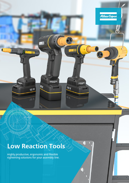
High-speed tightening – with low reaction toolsWhat is important in your tightening processes?Atlas Copco's low reaction tools close to eliminate the reaction force in assembly applications, delivering high-speed quality tightening while taking great care of the operator.Atlas Copco’s line-up of battery powered low reaction tools are designed to improve operator ergonomics. Not only will you increase productivity and optimize your factory up-time, you will also have less costs and time lost on operator injuries and fatigue.Choosing the right tool is the first – and most important – step towards a perfect operation. Regardless of which tool within our LRT range you choose, you will have a well balanced high quality tool. And choosing the right one will make the whole world of a difference.If you need a small and reliable workhorse that promises accuracy and speed, the pneumatic ErgoPulse PTI is an excellent solution.For maximum flexibility, high torque and the lowest vibration on the market – a cordless and powerful Atlas Copco TBP Pulse Tool is your choice.For reliable and accurate low reaction tightenings with lower torque, the cordless Tensor SRB offers an error-proof production.ErgoPulse PTI – your productive workhorseThe pneumatic, low weight ErgoPulse PTI is an excellent addition to the Atlas Copco LRT line-up. Increasing tool uptime with up to five times longer service intervals.With a durable and robust design the ErgoPulse PTI is faster and more accurate than ever and will improve the production quality and throughput. The ergonomic design of the tool takes care of your operators wellbeing, all while lowering the Total Cost of Ownership of your pulse tools. With fewer tool installations you can also enjoy lower set-up costs.The ErgoPulse PTI reduces the need formaintenance and is a proven and importantpart of this fleet. Our DuraPulse® technologymeans longer time between services with upto 5 x longer service intervals. With the rightstartup and maintenance you will have optimalperformance throughout the lifetime of the tool.With Torque Boost® the torque build-up is even faster, giving you reduced hoursper production unit. Quality is improved with a more robust and stable shut-offmechanism that increases accuracy and lowers the mean shift.Faster productionwith improved qualityQuality critical tightening and high productivity with the TBP-SThe all new cordless and slender TBP-S for one-handed operations, will ensure that your joint is tightened properly and trace the job done. Perfect for a reliable and quality critical tightening.With the same hardware as the TBP but with aslimmer software version suited for quality criticaltightenings, the TBP-S battery pulse tool is a robustyet slender solution for the middle segment. With amix of productivity, ergonomics and error-proofingthe TBP-S is proven to offer less maintenance andless down-time in production.Our DuraPulse® technology – also featured in theTBP – will ensure a robustness making the TBP-S areliable pulse tool that keeps on delivering.Low vibration and long service intervalsJust like the TBP, the TBP-S shows the lowestvibration levels in the market. This means operatorcomfort and safety, reducing work related costscaused by fatigue and injuries.The patented technology and design gives youlonger service intervals than with traditional pulsetools. With TorqueBoost®, the TBP-S has activecooling and advanced motor steering, so thetorque build up is fast and gives reduced hours perproduction unit.If you need morefunctionality in yourTBP-S you can easilyupgrade it to a fullyfunctional TBP withour upgrade kit.Future ProofSafety critical tightening and full traceability with the TBPSince launch, the TBP has been redefining what a low reaction pulse tool can do. Enjoy the benefits of a cordless tool for one-handed operations, enabling error-proof production.The Atlas Copco TBP is a reliable and powerful pulsetool, offering high torque tightening with very littlereaction. Giving you speed, accuracy, traceabilityand flexibility – with cordless freedom. With a TBPyou will have direct and accurate feedback of thejoint behavior.Anything is possible. Bring Error-Proofing to thenext level with our Barcode reader (EHMI) and alocation system like the ILT. Customize your toolwith accessories to fit your specific needs.Thanks to the patented technology and design,you will have longer service intervals than witha traditional pulse tools. Reduced oil leakage,separation of air and oil, and a cooler tool –meaning higher performance and uptime.Offering better protectionBV from injuries andincreasing the lifespan of your tools, results in hugesavings.Error-proof production with the cordless Tensor SRBThe Atlas Copco Tensor SRB delivers multipletightening technologies with accuracy, traceability, flexibility – and low reaction. It offers both traditional strategies like 2 steps and Quick Step, but also more advanced strategies such as TurboTight and TensorPulse. With a slim design it allows for easy access in cramped spaces.The Tensor SRB has low weight and great balance – with a slim design – ergonomically designed to prevent operator fatigue. New electronics and an improved motor will boost your productivity. Choose between 18v or 36v battery withoutcompromising the performance of speed or torque.Total Flexibility, Direct Drive, TurboTight™ and TensorPulseThe productive and cordless Tensor SRB will change the way you plan your assembly stations. Experience low reaction, one-handed operations with a strategy that fits your needs.DHD EEENTQSOORRLJJJKKKBBBBPFFCCAAGA B C D E F G H J K L NO PQ RSpacked with smart and innovative solutions. All to support our promise of delivering exactly the tool you need.A complete offerA flexible offer – Choose the functionality you needEach specific assembly has its own unique needs when it comes to functionalitylevel. With our flexible offer it is easy to find just the tool to get the job done, andfit it into your existing fleet. This, in combination with a common controller andvirtual stations, will lead to the best set up for your specific needs.Virtual stations: One controller – any toolIn a traditional assembly environment you willhave a vast range of reporting and non-reportingtools with different functionality, communicatingto a large number of controllers. Severalcontrollers, each controlling just the one tool.With Atlas Copco Virtual Stations you have onecontroller for multiple tools and reporting levels.Guided Rotaction socketsOur Rotaction concept promotes the increasing demands regarding operators safety and non-marking tools.The combination of free rotating sleeves and toolcovers for the connections "tool-to-socket" and socket covers for "extension-to-socket" improve operators safety significantly. This also eliminates user influence on the tightening.Thanks to extra stability from the elongated sleeve the socket delivers correct torque to the joint.Ergonomically this stability also protect operators from injury such as "white finger syndrome"Paired together we call it "Guided Rotaction".It protects your operators and maintains accuracy in your tightenings.Taking good care of your operators safety while maintaining joint accuracyBesides a wide range of standard products, customized solutions such as sockets, tool covers, multiples and much more can be realized with our team in Tierp, SwedenThe Rotaction range covers:¥Numerous sockets, bit sockets, bits and nut setters with freely rotating protection sleeves ¥Tool covers to bridge gaps between tool and socket ¥Socket covers to bridge gaps between extension and socket ¥Various extensions with rotating protection sleevesGuided socketWith Guided Rotaction the socket extends past the square drive A to give extra stability. The socket is held stable and eliminates wobbling thus maintaining force and improving operator comfort. This design is also found on our guided rotaction extensions.Rotaction covered socketsThe yellow sleeve B protects the user while the socket rotates on the inside. This provides a safer operation andminimized risk of scratches and marks on painted surfaces. It also eliminates any operator influence on the tightening. A tool cover C closes the gap between tool and socket protecting the operator from glove entanglement .BCAGuided Rotaction Sockets:¥Ergonomic¥Minimizes risk for injuries¥Eliminates user influence on the tightening ¥Gives extra stability ¥No scratching¥Delivers correct torque to the jointTake care of your investmentsEvery production line and industrial site is unique and has its own challenges. With that in mind, our service solutions are designed to help you get the most out of your industrial equipment. We combine analyses of production data with know-how and expertise in order to enhance your productivity and quality; while keeping you cost efficiency maintenance under control.Easystart – Right the First TimeNo two installations are the same. With Easystart it is easy to customize accordingto the customer needs per station. A trouble-free and efficient start of operationsfor your tightening system. Through a globally standardized and certified processfor every step, from programming to training, you will get it right the first time,saving time and money.ToolCover Maintenance Solutions help you optimize performance and gainefficiencies in your production while minimizing your tool costs and productionrisks. With a modular set of products, ToolCover is designed to meet your specificneeds and tool usage.Based on your needs, you can choose between Protect, Stability, Uptime.PreventiveMaintenanceOnce per tool and year Optimization based on historicproduction dataOptimization based on real-timeproduction dataKPI Monitoringand analysisYearly direct cost tracking Bi-annual direct and indirect costtracking per toolCustomized real-time monitoring andmonthly optimization analysis per tool Warranty Extended 3 month warranty aftermaintenanceFull contract lifetime warranty Full contract lifetime warrantyAtlas Copcoprofessional supportAnnual feedback meetings Bi-annual feedback andoptimization consultancyDedicated on-site Atlas Copco personnelRepairs Not included - but possible tocouple with RapidRepair contractYes - priority on workshop repairsand spare parts includedYes - included on-site supportRead more about our service offers at Take care of yourinvestmentsIncreasing valueIncreasing use ofproduction dataOptimize your tools –minimize your costsGuard your tools – maximizeyour productivityUptimeQualityCost eff.ModelBolt size mm Square drive in Torque range 1Free speed 2 r/min Weight Length mm CS dist mm Airconsumption under load Rec. hose size mm Air inlet thread in Ordering No.Nm ft lb kg lb l/s cfm High Pressure 3EP5PTI19 HR10-MT M63/88-196-1473000.9216823 6.51481/48431 0381 30 EP5PTI17 HR42-MT M61/4⁵7-175-1373000.9216823 6.51481/48431 0381 32EP6PTI32 HR10-MT M6-M83/816-3212-2390000.921682361381/48431 0381 40EP6PTI28 HR42-MT M6-M81/4⁵15-2811-2195000.921682361381/48431 0381 42EP7PTI55 HR10-MT M8-M103/830-5522-407000 1.2 2.517927919101/48431 0381 50EP8PTI70 HR10-MT M103/840-7029-517100 1.3 2.8179271021101/48431 0381 55EP9PTI80 HR13-MT M101/250-8037-595200 1.5 3.3191311328101/48431 0381 60EP11PTI100 HR13-MT M121/270-10052-744200 1.7 3.7201311430101/48431 0381 65EP13PTI150 HR13-MT M12-M141/285-15063-1105300 2.35201361532133/88431 0381 70Low pressure4EP5PTI15 HR10-MT-L M53/87-155-1169000.9216823 6.31381/48431 0382 30EP5PTI13 HR42-MT-L M4-M51/4⁵6-134-1069000.9216823 6.31381/48431 0382 32EP6PTI25 HR10-MT-L M63/813-259-1882000.921682361381/48431 0382 40EP6PTI25 HR42-MT-L M51/4⁵11-228-1682000.921682361381/48431 0382 42EP7PTI35 HR10-MT-L M63/823-3517-266200 1.2 2.517927615101/48431 0382 50EP8PTI45 HR10-MT-L M6-M83/833-4524-336300 1.3 2.817927817101/48431 0382 55EP9PTI65 HR13-MT-L M101/243-6532-484500 1.5 3.3191319.520101/48431 0382 60EP11PTI80 HR13-MT-L M10-M121/250-8037-593600 1.7 3.7201311328101/48431 0382 65EP13PTI110 HR13-MT-LM12-M141/263-11046-8140002.35201361634133/88431 0382 70Accessories Ordering No.Oil filling kit4250 3220 90Protective cover EP5/6PTI 4250 3209 00Protective cover EP7/8PTI 4250 3206 00Protective cover EP9PTI 4250 3216 00Protective cover EP11PTI 4250 3218 00Protective cover EP13PTI 4250 3214 00Quick Change Chuck4250 3218 00ErgoPulse PTIProtective cover is included for every tool1To be used as a guide only, final torque depends on type of joint, accessories used and air pressure.² In full speed mode³ Air pressure 6.3 bar / 91 psi ⁴ Air pressure 4 bar / 58 psi ⁵ Female Hexagon drive, Quick Change ChuckModelSquare Drive Guide Socket Torque range Nm ft lb ETP SRB31-25-103/8135-25 3.7-18.4ETP SRB31-25-I061/41135-25 3.7-18.4ETP SRB31-25-10-BD 3/8135-25 3.7-18.4ETP SRB31-25-I06-BD1/41135-25 3.7-18.4ETP SRB31-20-103/8125-20 3.7-14.75ETP SRB31-20-I061/41125-20 3.7-14.75ETP SRB31-20-10-BD 3/8125-20 3.7-14.75ETP SRB31-20-I06-BD 1/41125-20 3.7-14.75ETP TBP61-32-103/81312-358.9-25.8ETP TBP61-32-10-BD 3/81312-358.9-25.8ETP TBP61-32-421/411312-358.9-25.8ETP TBP61-32-42-BD 1/411312-358.9-25.8ETP TBP81-55-103/81320-5514.8-40.6ETP TBP81-55-10-BD 3/81320-5514.8-40.6ETP TBP91-80-131/21840-8029.5-59.0ETP TBP91-80-13-BD 1/21840-8029.5-59.0ETP TBP131-150-131/21855-15059-110ETP TBP131-150-13-BD 1/21855-15059-110ETP TBPS61-32-103/81312-359-26ETP TBPS61-32-421/411312-359-26ETP TBPS81-55-103/81320-5515-41ETP TBPS91-80-131/21830-8022-59ETP TBPS131-150-131/21855-15041-111ModelMax TorqueTensorPulse Nm ft lb Nm ETP SRB 31-20-102014.7516ETP SRB 31-25-102518.425Model Square Drive Input d mmLength mm Ordering No.Extension 1003/8251004027 1234 72Extension 1503/8251504027 1234 74Extension 2503/8252504027 1234 77Reference Code Square Drive Input d mmLength mm Ordering No.C223/8227.54027 1297 90C253/8257.54027 1297 91Model Length mm Square Drive Input d mmSocket Cover Ref.Ordering No.Socket 88503/822C224027 1292 08Socket 1010503/822C224027 1292 10Socket 1212503/822C224027 1292 12Socket 1313503/825C254027 1292 13Socket 1616503/825C254027 1292 16Socket 1717503/825C254027 1292 17ModelSquare Drive Guide socket Input d mm Length mmOrdering No.ETP TBP61-32-10ETP TBP61-32-10-BD ETP TBPS61-32-103/81322 & 259.54027 1297 30Batteries Ordering No.Ugrade kit TBP-S64211 5645 30Ugrade kit TBP-S84211 5645 31Ugrade kit TBP-S94211 5645 32Ugrade kit TBP-S134211 5645 33AccessoriesOrdering No.Protective cover TBP6 & TBP84250 3135 60Protective cover TBP94250 3135 62Protective cover TBP134250 3135 63SRB/TBP Tool Holder 4220 3584 86 Protective cover SRB 4220 2744 07 AccessoriesFoot protective cover Protective cover 18V Protective cover 36V STB Battery Charger Adapter4211 6083 87Tensor SRB Torque RangesLow Reaction Battery ToolsGuided Rotaction Extensions 13 Socket covers, Rotaction Guided Rotaction Sockets 13 Tool cover for Guided Rotaction Sockets TBP-S Upgrade kit Accessories 25 mm22 mmLdTool covers, Guided Rotaction sockets and others that aren't listed here can be special requested from our Competence Center Sockets & Bits1 0 9 0 123 3 8 9。
最新ark方舟_最新整理物品id资料

全物品ID Item ID Item Description1 Simple Pistol简易手枪2 Assault Rifle 突击步枪3 Rocket Launcher火箭发射器4 Simple Bullet简单子弹5 Bow弓6 Genade手榴弹7 Wood木材8 Stone石头9 Metal金属10 Hide兽皮11 Chitin甲壳12 Raw Meat生肉13 Spoiled Meat变质肉14 Cooked Meat熟肉15 Water Jar水瓶16 Water Jar (Full) 水瓶(满)17 Cloth Pants布裤18 Cloth Shirt布衬衫19 Cloth Hat布帽20 Cloth Boots布靴21 Cloth Gloves布手套22 Hide pants皮裤23 Hide Shirt皮衬衫24 Hide Hat皮帽25 Hide Boots皮靴26 Hide Gloves皮手套27 Chitin Leggings甲壳护腿28 Chitin Chestpiece甲壳胸甲29 Chitin Helmet甲壳头盔30 Chitin Boots甲壳靴31 Chitin Gauntlets甲壳护手32 Stone Arrow石箭33 Stone Pick石镐34 Stone Hatchet石斧35 Metal Pick铁镐36 Metal Hatchet铁斧37 Torch火把38 Paintbrush漆刷39 Campfire篝火40 Standing Torch立式火把41 Hide Sleeping Bag睡袋42 Remote Detonator遥控雷管43 C4 Charge C4控制器44 Blood Extraction Syringe采血器45 Blood Pack血包46 Improvised Explosive Device简易爆炸装置47 Waterskin水袋48 Waterskin(Full) 水袋(满)49 Berrybush Seeds浆果种子50 Fertilizer肥料51 Bingleberry Soup52 Medical Brew医疗补酒53 Energy Brew能量补酒54 Dinosaur Feces恐龙粪便55 Human Feces人类粪便56 Stegosaurus Egg剑龙蛋57 Spear长矛58 Red Coloring红色染料59 Green Coloring绿色染料60 Blue Coloring蓝色染料61 Yellow Coloring黄色染料62 Purple Coloring紫色染料63 Orange Coloring橙色染料64 Black Coloring黑色染料65 White Coloring白色染料66 Brown Coloring褐色染料67 Cyan Coloring青色染料68 Purple Coloring紫色染料69 Rex Saddle暴龙鞍70 Tranq Arrow麻醉箭71 Pistol Hat Skin72 GPS全球定位系统73 Flint燧石74 Metal Ingot金属锭75 Thatch茅草76 Fiber纤维77 Charcoal木炭78 Crystal水晶79 Thatch Roof茅草屋顶80 Thatch Door茅草屋的门81 Thatch Foundation茅草地基82 Thatch Wall茅草墙83 Thatch Doorframe茅草屋的门框84 Wooden Catwalk木制小道85 Wooden Ceiling木制天花板86 Wooden Hatchframe木制天窗门框87 Wooden Door木门88 Wooden Foundation木地基89 Wooden Ladder木梯90 Wooden Pillar木支柱91 Wooden Ramp木坡道92 Wooden Trapdoor木制天窗活动门93 Wooden Wall木墙94 Wooden Doorframe木制门框95 Wooden WindowFrame木制窗框96 Wooden Window木窗97 Wooden Sign木制指示牌98 Blueprint: Note蓝图:注释99 Citronal柠檬100 Parasaur Saddle副栉龙鞍101 Raptor Saddle迅猛龙鞍102 Stego Saddle剑龙鞍103 Trike Saddle三角龙鞍104 Pulmonoscorpius Saddle帝王蝎鞍105 Storage Box小存储箱106 Large Storage Box大储物箱107 Mortar and Pestle研磨器皿108 Sparkpowder火花粉109 Gunpowder火药110 Stone Irrigation Pipe – Intake石灌溉管道入水管111 Stone Irrigation Pipe - Straight石灌溉管道直管112 Stone Irrigation Pipe - Inclined石灌溉管道斜切面管113 Stone Irrigation Pipe - Intersection石灌溉管道十字管114 Stone Irrigation Pipe - Vertical石灌溉管道垂直管115 Stone Irrigation Pipe - Tap石灌溉管道出水龙头116 Amarberry Seed黄色浆果种子117 Amarberry黄色浆果118 Azulberry蓝色浆果119 Tintoberry红色浆果120 Mejoberry紫色浆果121 Narcoberry黑色浆果122 Stimberry白色浆果123 Narcotic麻醉剂124 Stimulant兴奋剂125 Refining Forge精炼炉126 Smithy工作台127 Compost Bin堆肥箱128 Cooking Pot烹调锅129 Simple Bed简易床130 Small Crop Plot小型种植地131 Pteranodon Saddle无齿翼龙鞍132 Longneck Rifle长管步枪133 Citronal Seed柠檬种子134 Specimen Implant135 Bronto Saddle雷龙鞍136 Wooden Fence Foundation木篱笆137 Compass指南针138 Scope Attachment瞄准镜139 Slingshot弹弓140 Pike铁矛141 Radio无线电142 Obsidian黑曜石143 Dinosaur Gatewa木制中型恐龙大门门框144 Simple Rifle Ammo简易步枪弹药145 Summon Broodmother召唤巨型蜘蛛-育母蜘蛛146 Cementing Paste水泥147 Dinosaur Gate木制中型恐龙大门148 Artifact of the Hunter召唤物品149 Artifact of the Pack召唤物品150 Artifact of the Massive召唤物品151 Artifact of the Devious召唤物品152 Artifact of the Clever召唤物品153 Artifact of the Skylord召唤物品154 Artifact of the Devourer召唤物品155 Artifact of the Queen召唤物品156 Artifact of the Strong召唤物品157 Artifact of the Flamekeeper召唤物品158 Argentavis Talon阿根廷巨鹰的爪159 Megalodon Tooth巨齿鲨的牙齿160 Tyrannosaur Arm暴龙的爪161 Sauropod Vertebra雷龙的脊椎162 Oil石油163 Silica Pearls珍珠164 Gasoline汽油165 Electronics电路板166 Polymer聚合物167 Metal Catwalk金属小道168 Metal Ceiling金属天花板169 Metal Hatchframe金属天窗门框170 Metal Door金属门171 Metal Fence Foundation金属围栏172 Metal Foundation金属地基173 Behemoth Gate巨型恐龙大门174 Behemoth Gateway巨型恐龙大门门框175 Metal Ladder金属梯子176 Metal Pillar金属立柱177 Metal Ramp金属斜坡178 Metal Trapdoor金属天窗活动门179 Metal Wall金属墙180 Metal Doorframe金属门框181 Metal Windowframe金属窗框182 metal Window金属窗183 Super Test meat超级实验肉184 Flare Gun信号枪185 Fabricator制作间186 Water Tank储水池187 Parachute降落伞188 Air Conditioner空调189 Electrical Generator发电机190 Electrical Outlet电源插座191 Inclined Electrical Cable斜电缆192 Electrical Cable Intersection十字电缆193 Straight Electrical Cable电缆194 Vertical Electrical Cable垂直电缆195 Lamppost灯柱196 Refrigerator冰箱197 Auto Turret自动炮塔198 Remote Keypad远程遥控面板199 Metal Irrigation PipInclined斜切面金属管道200 Metal Irrigation Pipe Tap金属水龙头201 Metal IrrigatioIntersection十字金属管道202 Metal irrigation Pipe Straight金属直管203 Metal Irrigation Pipe Tap金属水龙头204 Metal Irrigation PipVertical垂直金属管道205 Flashlight Attachment手电筒挂件206 Silencer Attachment消音器207 Carbonemys Saddle碳龟鞍208 Sarco Saddle帝鳄鞍209 Ankylo Saddle甲龙鞍210 Mammoth Saddle猛犸象鞍211 Megalodon Saddle巨齿鲨鞍212 Sabertooth Saddle剑齿虎鞍213 Carno Saddle牛龙鞍214 Argentavis Saddle阿根廷巨鹰鞍215 Plesiosaur Saddle蛇颈龙鞍216 Chitin/Keratin角质素217 Keratin角蛋白218 Metal Sign金属指示牌219 Holo-Scope Attachment全息瞄准镜220 Laser Attachment激光瞄准镜221 Wooden Billboard木制告示牌222 Flak Leggings防弹护腿223 Flak Chestpiece防弹衣224 Flak Helmet防弹头盔225 Flak Boots防弹靴226 Flak Gauntlets防弹护手227 Enduro Stew耐力炖汤228 Lazarus Chowder拉撒路杂烩229 Calien Soup卡里安清新汤230 Fria Curry弗里亚咖喱231 Focal Chilli聚神辣椒232 Savoroot土豆233 Longgrass玉米234 Rockarrot胡萝卜235 Azulberry Seed蓝色浆果种子236 Tintoberry Seed红色浆果种子237 Mejoberry Seed紫色浆果种子238 Narcoberry Seed黑色浆果种子239 Stimberry Seed白色浆果种子240 Savoroot Seed土豆种子241 Longgrass Seed玉米种子242 Rockarrot Seed胡萝卜种子243 Metal Billboard金属告示牌244 Fabricated Pistol制式手枪245 Advanced Bullet高级子弹246 Advanced Rifle Bullet高级步枪子弹247 Rocket Propelled Grenade火箭弹248 Medium Crop Plot中型种植田249 Large Crop Plot大型种植田250 Rare Flower稀有花朵251 Rare Mushroom稀有蘑菇252 Raw Prime Meat生大腿肉253 Cooked Prime Meat熟大腿肉254 Battle Tartare战斗神丸255 Shadow Steak Saute暗影煎牛排256 Rockwell Recipes: Enduro Stew罗克韦尔食谱:耐力炖汤257 Rockwell Recipes: Lazarus Chowder罗克韦尔食谱:拉撒路杂烩258 Rockwell Recipes: Calien Soup罗克韦尔食谱:卡里安清新汤259 Rockwell Recipes: Fria Curry罗克韦尔食谱:弗里亚咖喱260 Rockwell Recipes: Focal Chilli罗克韦尔食谱:聚神辣椒261 Rockwell Recipes: Battle Tartare罗克韦尔食谱:战斗神丸262 Rockwell Recipes: Shadow Steak Saute罗克韦尔食谱:暗影煎牛排263 Notes on Rockwell Recipes罗克韦尔食谱说明书264 Wall Sign木制墙标265 Metal Dinosaur Gat金属恐龙大门门框266 Metal Dinosaur Gate金属恐龙大门267 Shotgun散弹枪268 Simple Shotgun Ammo简易散弹269 Metal Wall Sign金属墙标270 Amarberry Seed黄色浆果种子271 Azulberry Seed蓝色浆果种子272 Tintoberry Seed红色浆果种子273 Narcoberry Seed黑色浆果种子274 Stimberry Seed白色浆果种子275 Mejoberry Seed紫色浆果种子276 Citronal Seed柠檬种子277 Savaroot Seed土豆种子278 Longgrass Seed玉米种子279 Rockarrot Seed胡萝卜种子280 Flag旗帜281 Hunter Skin Hat猎人皮帽子282 Rex Stomped Glasses Sadd暴龙眼镜鞍283 Spyglass望远镜284 Spider Flag285 Phiomia Saddle渐新象鞍286 Medium Dinosaur Feces中型恐龙粪便287 Large Dinosaur Feces巨型恐龙粪便288 Brontosaurus Egg雷龙蛋289 Parasaur Egg副栉龙蛋290 Raptor Egg迅猛龙蛋291 T-Rex Egg暴龙蛋292 Triceratops Egg三角龙蛋293 Parasaur ARK Founder Saddle Skin副栉龙鞍(方舟系统赠送)294 Dodo Egg渡渡鸟蛋295 烘干箱296 铁刺297 肉干298 腿肉干299 霸王龙头盔300 装逼眼镜301 菜谱medical brew302 菜谱 energy brew303 spino saddle304 菜单肉干305 矿工帽306 保险柜307 木刺308 恐龙老花镜309 蓝图柜310 石围墙地基311 石墙312 铁水箱313 plesiosaur saddle314 海豚鞍315 石屋顶316 石狗洞顶317 石门318 石地基319 石龙门320 石龙门框321 石柱322 石门框323 石窗框324 独立日烟花325 毒气陷阱326 警报器327 kibble (ankylo egg) 328 kibble(argentavis egg) 329 kibble(titanboa egg) 330 kibble(carno egg) 331 kibble(dilo egg) 332 kibble(dodo egg) 333 kibble(parasaur egg) 334 kibble(pteranodon egg 335 (rapator egg) 336 (rex egg) 337 (sarco egg) 338 (bronto egg) 339 (蝎卵) 340 (araneo egg) 341 (spino egg) 342 (stego egg) 343 (trike egg) 344 (王八蛋) 345 ankylo egg 346 argentavis egg 347titanboa egg348 carno egg 349 dilo egg 350 pteranodon egg 351 sarco egg 352 蝎卵353 araneo egg 354 spino egg 355 turtle egg 356 菜谱egg-based kibble357 石窗358 石狗洞顶门359 多向路灯360 大烤炉361 连发散弹362 弩363 绿色364 微黄365 粉366 紫367 白368 淡蓝369 淡黄370 深黄371 彩色蛋挞372 恐龙定位373 恐龙gps374 白旗375 饲料槽376 铁弓377 铁箭378 水壶379 水壶满380 镰刀381 石巨兽门框382 石巨兽门383 捕兽夹384 大捕兽夹385 三角龙头骨386 稀有肥料387 氧气瓶388 潜水眼睛389 脚蹼390 X物种子 391 X物种子392 喷漆枪393 星尾兽鞍394 斜茅草屋顶395 茅草左墙396 茅草右墙397 斜木屋顶398 木左墙399 木右墙400 斜石屋顶401 石左墙402 石右墙403 斜金属屋顶404 金属左墙405 金属右墙406~412 各色染料413 洗点水414 木筏415 雷龙平台鞍417 肿头龙鞍418 肿头龙蛋419 肿头龙蛋饲料配方420 洗点水配方421 油画画布422 巨蜥鞍423 巨蜥鞍平台424 毛皮425 dimorph egg427 双齿翼龙饲料。
伯克林斯4.248.2 Diesel Thru U108196N引擎维修工具包说明书
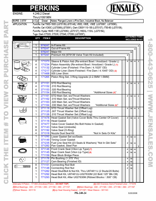
APPLICATION: Forklifts: Cat T50D-150D (LG70109,LG70149); V80D, V80E, V90E (LG70067, LG70090);Forklifts: Cat VC60C (LG70069,LG70091); Clark C500Y110-155 (LG70107); IT50-80 (LG70106); Forklifts: Hyster H60E-110E (LG70063, LG70127); H60XL-110XL (LG70184);Tugs: Clark CTD20, CTD30, CTD40, CTD50 (LG70097);QTY ITEM # DESCRIPTION LETTERED ITEMSINCLUDED IN KIT1 974247 In-Frame Kit I1 975247 Out-of-Frame Kit O1 976247 Major Kit M1 977247 Premium Kit (979139 Valve Train Kit Included) P4 4 4 4 4 171373 171234 171132 171217 171468 Sleeve & Piston Asb (Re-entrant Bowl / Anodized / Grade L) Piston Assembly (Re-entrant Bowl / Anodized / Grade L) (1)Cylinder Liner (Finished / Fire Dam / 4.1025" OD)Cylinder Liner (Semi-Finished / Fire Dam / 4.1045" OD) (2)005 Liner ShimP M O I4 171265 Piston Ring Set, 3 Ring Upgrade (2-2.5MM 1-5MM)4 4 4 4 271151 271152 271153 271154 STD Rod Bearing .010 Rod Bearing.020 Rod Bearing.030 Rod Bearing "Additional Sizes (5)"P M O I1 1 1 1 271161 271162 271163 271164 STD Main Set, wo/Thrust Washers .010 Main Set, wo/Thrust Washers.020 Main Set, wo/Thrust Washers.030 Main Set, wo/Thrust Washers "Additional Sizes (6)"P M O I1 1 1 271119 271125 271126 STD Thrust Washer Set (Offset Lug) .007 Thrust Washer Set (Offset Lug).010 Thrust Washer Set (Offset Lug)P M O I1 1 1 8 8 4 371478 371116 371477 371143 371192 371318 Head Gasket Set (Valve Cover Bolts Thru Center Of Cover) Head GasketValve Cover Gasket (No Bolt Holes In Gasket)Valve Seal (Umbrella)Valve Seal (O-Ring)Nozzle Dust Seal Kit "Not In Sets Or Kits"P M O I1 1 1 1 371292 371149 371235 371282 Lower Gasket Set wo/Seals Timing Cover Gasket Fuel Line Seal Kit (23 Seals & Washers) "Not In Gkt Sets" Pan Gasket, Steel Pan P P M M O OI1 1 1 371146 371145 771159 Front Crank Seal (Viton Lip Type) (7) Rear Crank Seal (Viton Lip Type) (8) Rear Block Bridge PieceP P M M O O4 1 271176 271127 Pin Bushing (1.375" Pin) Cam Bearing (Finished ID) P P M M8 8 1 1 1 771151 771148 771282 771292 771293 Connecting Rod Bolt Connecting Rod Nut Head Stud/Bolt & Nut Kit, Thru U874811J (2 Studs/20 Bolts)Head Bolt Kit, U874812J-U027630M (22 Bolt/.125" Blk CB)Head Bolt Kit, After U027630M (Ribbed Blocks / .500" CB)P P M M(1)Grade H Piston - 171483 (Anodized Piston - DO NOT TOP ) (2).020 Oversize Semi-Finished Liner - 171478(5)Rod Bearings: .040 - 271155 / .050 - 271156 / .060 - 271157 (6)Main Bearings: .040 - 271165 / .050 - 271166 / .060 - 271167(7)Wear Sleeve - 301115 (8)Lip Seal Housing Gasket - 371187 / Wear Sleeve - 301143Forklifts: Cat VC60C (LG70069,LG70091); Clark C500Y110-155 (LG70107); IT50-80 (LG70106); Forklifts: Hyster H60E-110E (LG70063, LG70127); H60XL-110XL (LG70184);QTY ITEM # DESCRIPTION LETTERED ITEMSINCLUDED IN KIT1 979517 Camshaft Kit C1 979143 Valve Train Kit V1 979139 Valve Train Kit, w/Guides V1 571114 Camshaft "Cam Bolt Lock Plate - 571162" C1 271249 Camshaft Thrust Washer (1.750 X 2.873 X .217)8 571123 Tappet C4 4 471123 471128 STD Exhaust Valve (45º / Bi-Metal) (10) STD Intake Valve (45º / Alloy / Chromed Stem) (11) V V V V4 471132 Exhaust Guide: Service Repair or 1985 & Up V4 471131 Intake Guide: Service Repair or 1985 & Up V8 471134 Outer Valve Spring (8 Coils / 2.500" Free Length) V V8 471133 Inner Valve Spring (9 Coils / 2.000" Free Length) V V8 471219 Spring Seat, Integral Guides "With Service Guides - 471229"8 471222 Spring Retainer16 471146 Keeper (Half) V V4 471111 Exhaust Seat (1.248 x 1.681 x .374 Stepped Top)4 471113 Intake Seat (1.594 x 2.020 x .281)4 471224 LH Rocker Arm (Adj Screw & Lock Nut Not Included) (12)4 471225 RH Rocker Arm (Adj Screw & Lock Nut Not Included) (12)1 471227 Rocker Arm Shaft (13) "Includes 471176 Plugs"1 571112 Cam Gear: Except Below (Cast / 56 Teeth)1 571165 Cam Gear: LG70067, LG70090 (Steel / 56 Teeth) 1 571113 Crank Gear: Except Below (28 Teeth)1 571166 Crank Gear: LG70067, LG70090 (Steel / 28 Teeth)1 571163 Idler Gear: Except Below (Steel / 63T) (14)1 571167 Idler Gear: LG70067, LG70090 (Steel / 63 Teeth) (15)8 571117 Push Rod1 671112 Oil Pump1 671134 Oil Pump Idler Gear1 571124 Idler Gear Bushing1 671148 Relief Valve Assembly (Engines w/LH Oil Filter Only)1 671156 Relief Valve Assembly (Engines w/RH Oil Filter Only)1 771132 Crank Kit (Spline Nose / Lip Seal)4 771154 Connecting Rod (1.375" Pin)1 771264 Cylinder Head Assembly (Includes Valves & Springs)1 771286 Expansion Plug Kit (Includes 19 Plugs For Head & Block)1 871162 Thermostat: Except Below (2.125")1 871138 Thermostat: LG70149 (2.125" / Bypass)1 871147 Water Pump wo/Pulley: Except Below1 871173 Water Pump wo/Pulley: LG701491 871228 Block Heater (1.250")1 871152 Fuel Pump, Late (4 Bolt)(12)Adj Screw - 471226 / Lock Nut - 571139 (13)Snap Ring - 471228 (14)Includes 2 Bush - 571144 (15)Needle Bearings - 571168。
拜科奇产品手册

目录
.1 . . . . . .1 .1.1 .1. .1. .1. .1. . ..1 .. .1 . . . . . . . 10 11
拜科奇的产品特性 ......................................................................................................... 质量保证........................................................................................................................ 产品纯度........................................................................................................................ 耐受性和安全性的临床前证据 ....................................................................................... 临床前免疫原性模型...................................................................................................... 临床前疗效研究............................................................................................................. 拜科奇临床前研究小结 .................................................................................................. 临床研究........................................................................................................................ 对既往接受过治疗的患者(PTPs)的研究.................................................................... 0 药代动力学 .................................................................................................................... 0 疗效............................................................................................................................... 临床免疫原性 ................................................................................................................ 外科手术中的应用 ......................................................................................................... 安全性 ........................................................................................................................... 对既往未接受过治疗(PUPs)或仅接受过最低限度治疗(MTPs)的患者的研究 ....... 拜科奇用于治疗PUPs/MTPs的安全性及疗效 ................................................................ PUPs/MTPs中抑制物的产生率...................................................................................... 重组人凝血因子VIII抑制物的形成.................................................................................. 1 抑制物形成的潜在标志物 .............................................................................................. 1 抑制物形成的发生率...................................................................................................... 抑制物分子 ................................................................................................................... 抑制物的特异性............................................................................................................. 对PTPs的临床免疫原性研究 ......................................................................................... PUPs/MTPs中抑制物发生率的比较 ............................................................................. 抑制物产生的累积风险 .................................................................................................. 0 小结:拜科奇与凝血因子VIII抑制物 .............................................................................. 1 免疫耐受诱导 (ITI) ........................................................................................................ 长期预防........................................................................................................................ 产品亮点总结 ................................................................................................................ 0 参考文献........................................................................................................................
转炉副枪(DANIELI)

Table of Contents
1. 1.1 1.2 1.3 1.4 1.5 1.6 1.7 1.8 2. 2.1 2.2 2.3 2.4 3. 3.1 3.2 4. 4.1 4.2 4.3 4.4 5. 5.1 6. 6.1 7. 7.1 7.2 7.3 7.4 GENERAL TECHNICAL DESCRIPTION ..................................................................... 4 Introduction................................................................................................................... 4 Short description of Scope of supply ............................................................................ 4 Steelmaking conditions, basic technical data and parameters ..................................... 4 Media condition ............................................................................................................ 7 Functional Requirements............................................................................................. 8 Sublance Basic Design Data ........................................................................................ 9 Critical Dimensions....................................................................................................... 9 General Technical Description ................................................................................... 10 TECHNICAL SPECIFICATION................................................................................... 29 Sublance Equipment Mechanical ............................................................................... 29 Sublance Piping and Utilities ...................................................................................... 36 Technical specification for auxiliary facilities .............................................................. 38 Electrical , Instrumentation and Automation ............................................................... 41 DIVISION OF SCOPE OF SUPPLY BETWEEN SELLER AND BUYER.................... 53 Sublance Scope of Supply of Seller and Buyer .......................................................... 53 Exclusions .................................................................................................................. 59 SCOPE OF DESIGN AND DEVISION BETWEEN SELLER AND BUYER ................ 61 Scope of Engineering ................................................................................................. 61 Software supply conditions......................................................................................... 63 Manuals ...................................................................................................................... 63 Format and Quantities ................................................................................................ 64 THE TECHNICAL DOCUMENTATION DELIVERED BY SELLER TO BUYER AND THEIR DELIVERY SCHEDULE ................................................................................. 65 Transfer of Sublance basic information, basic and detail engineering ....................... 65 THE TECHNICAL DOCUMENTATION DELIVERED BY BUYER TO SELLER AND THEIR DELIVERY PROCEDURE .............................................................................. 68 Reference Documents................................................................................................ 68 THE SELLER’S PERFORMANCE GUARANTEE FIGURES AND METHODS OF THE EXAMINATION AND ACCEPTANCE......................................................................... 69 Sublance Performance Guarantee ............................................................................. 69 SDM Performance Guarantee .................................................................................... 70 Performance guarantee of the Waste Gas Analyzer System ..................................... 72 Preconditions for Sublance performance guarantees ................................................ 73
海沃德游泳池清洁器说明书

2Limited WarrantyMakoShark 2KingSharkKingShark 2KingShark 2 w/RemoteTigerShark 2Tiger Shark 2 PlusYour Hayward Pool Cleaner has been manufactured, tested and inspected in accordance with carefully specified engineering requirements. It is warranted to be free from defects in materials and workmanship for a period of one year. Coverage is provided to the original owner only and is not transferrable. This limited warranty includes both parts and labor for the cleaners listed above. This warranty gives you specific legal rights. You may also have other rights, which vary from state to stateEXCEPTIONS AND EXCLUSIONS FROM WARRANTYDamage, malfunctions orrising from improper electrical supply levels are excludedfrom this warranty. Malfunctions, failure or damage of the cleaner caused by improper, unreasonable, or negligent use or abuse by the consumer, are excluded from this warranty.Any repair that is made on your cleaner during the warranty period by anyone other than an Authorized Hayward Warranty Service Center (designated to perform such work) will void this warranty and other warranty rights you may have. Filter cartridges and debris bags are not covered by this warrantyINSTRUCTIONS TO OBTAIN WARRANTY REPAIRTo obtain repair of your Hayward cleaner under this warranty, the following procedure must be followed:• Locate and deliver the cleaner to the nearest Hayward Factory Authorized Warranty Service Center. Your Authorized Hayward Warranty Service Center can be located by visiting . You may also call 908-355-7955 to locate you nearest authorized service center. Cost of transportation, if required, is at the sole expense of the owner. Proof of purchase is required.TERMSIf a warranty claim is made and the product delivered to an Authorized Hayward Warranty Service Center within the warranty period, your Hayward cleaner will be repaired at no charge (parts & labor) to you. Listed warranty exclusions apply.No dealer, distributor, or other similar person has any authority to make any warranties or representations concerning Hayward Pool Cleaner products or to extend this warranty beyond the express items contained herein. Accordingly, Hayward Pool Products assumes no responsibility for any such warranties or representations beyond the express items contained in this limited warranty.WARRANTY REGISTRATION CARDYou can register your unit on-line by visiting or by filling out the registrationcard and returning it to:Hayward IndustriesAttn Warranty Department620 Division StreetElizabeth, NJ 07207CONTENTSSafety Precautions (2)General Information (3)Motor Information (4)Trouble Shooting (5)Specifications (7)Machine Assembly/Parts (8)Filter Assembly/Parts (10)Accessories (11)Preventive Maintenance (13)Parts Ordering Instructions (14)SAFETY PRECAUTIONSThe KingShark2 automatic swimming pool vacuum cleaner has been manufactured with the highest degree of care and concernfor safety. We suggest the following safety precautions become part of your pool safety regulations:1. ALWAYS PUT THE MACHINE INTO THE WATER BEFORE CON-NECTING IT TO THE ELECTRICAL OUTLET.2. IT IS IMPORTANT FOR SWIMMERS’ SAFETY TO REMOVETHE UNIT IMMEDIATELY FOLLOWING USE. THIS WILL ALSOIMPROVE THE OPERATING LIFE OF YOUR KING SHARK2.3. BE CERTAIN THE MACHINE IS ONLY PLUGGED INTO AGROUNDED ELECTRICAL OUTLET EQUIPPED WITH AGROUND FAULT CIRCUIT INTERRUPTER.4. DO NOT HANDLE MACHINE WHILE IT IS PLUGGED INTO THEELECTRICAL OUTLET.5. DO NOT USE AN EXTENSION CORD. THIS COULD CREATE ASAFETY HAZARD AND/OR DAMAGE YOUR UNIT.6. ALWAYS STAY OUT OF THE POOL WHILE CLEANER IS INOPERATION.7. NEVER ALLOW PLUG TO ENTER THE POOL.8. DO NOT OPERATE THE MACHINE OUT OF WATER. THIS WILLDAMAGE THE MOTOR SEAL AND VOID THE WARRANTY.9. DO NOT DRAG THE MACHINE OUT OF THE POOL AGAINSTTHE SIDE WALL. THIS COULD DAMAGE UNIT AND/OR YOURPOOL WALL.10. SOME POOLS HAVE A CORNER OR A CORNER STEP CON-FIGURATION THAT MAY CAUSE THE UNIT TO “HANG-UP;”THEREFORE, DO NOT LEAVE THE UNIT COMPLETELYUNATTENDED FOR MORE THAN 1/2 HOUR. OCCASIONALOBSERVATION AND ATTENDANCE CAN ALSO REDUCE ANYTENDENCY FOR THE CORD TO TWIST.While the KingShark2 has been made to operate as safely as possible, we suggest you exercise reasonable care in the handling of the vacuum and inspect the electrical cord frequently for damage or wear, as with any other electrical appliance. After use, remove the unit and rinse with fresh water and remove any twists that may be present in the cord.GENERAL INFORMATIONYou have purchased the finest piece of equipment in the pool cleaner industry. If you treat it as such, your KingShark2 automatic swimming pool vacuum cleaner will give you years of satisfactory service. As a suggestion, the unit should be stored in the original shipping container for safekeeping during the off season.ADJUSTMENTTHERE IS ONE ADJUSTMENT THAT MAY BE NECESSARY FOR USE IN YOURPOOL. PLEASE TAKE THE FEW MINUTES NECESSARY TO UNDERSTAND THIS SIMPLE PROCEDURE:1.2.3.4.1.2.3. The height of the sensor bar #3210 (Page 9, Key 2) is pre-set at the factory for average pools. It may be necessary to readjust the height of the sensor bar for the machine to operate satisfactorily in your pool.In “Free Form” or “Bowl Shaped” pools, the sensor bar may have to be raised to a higher setting to allow the machine to climb out of the deep end and clean up the radius or slope as far as possible without the machine turning over.Adjustment of the sensor bar #3210 (Page 9, Key 2) is made by loosening adjust- ing arm bolts #2121 B (Page 9, Key D) located just ahead of the intake. With the machine sitting on a level surface, loosen both adjusting arm bolts, and move sensor bar to desired position. Make certain the sensor bar is parallel to the level surface and retighten the adjusting arm.It may be necessary to reset the sensor bar several times to find the best position for operation in your pool. Sensor bar should glide freely. This can be checked by pushing back on the sensor bar which will activate the reversing arms.OPERATING INSTRUCTIONSSelect nearest grounded outlet supply of 110/115/220/240 voltage.CAUTION: avoid overloaded circuits as low or high voltage can damage your mo- tor. A connected ground is most important. Plug into outlet. Observe machine as it travels over bottom of pool.Allow machine to travel around the pool until it is clean. Average 75' x 150' pool will required approximately 4 hours. If the pool has a heavy accumulation of debris, it may be necessary to clean the filter several times during the vacuuming period. Upon completion of vacuuming the pool, allow the unit to travel to the shallow endof the pool. Before it reaches the pool wall, turn power off, raise the unit by the white nylon rope #1312, then remove the unit from the water by use of the handle. Allow excess water from the filter to drain into the pool with the KingShark2 resting on the edge or coping. Do not leave machine in water after disconnecting.4.5.6.7.8.KingShark2REMOVE THE UNIT IMMEDIATELY AFTER USE.ALLOWING UNIT TO COOL IN WATER AFTERRUNNING CAN CAUSE MOTOR SEAL DAMAGE.To clean the cartridge filters #7807 (Page 10, Key 7) remove the filter housing assembly #3400 (Page 10, Key 13) by removing the filter knob and releasing the filter box.Cleaning the filters after each use is an important part of maintaining your King- Shark2. Clean filters will allow the machine to function most efficiently.Disassemble the filter housing assembly #3400 (Page 10, Key l3) by removing the four (4) filter knobs #3405 (Page 10, Key 3) The filter backplate #3416 (Page 10, Key 10) and filter cartridges #7807 can then be removed.Clean cartridges with a water hose using a pressure nozzle.Use the KingShark2 on a regular basis to keep your pool clean.MOTOR INFORMATIONThe Motor in your KingShark2 has automatic overload protection. The overload switch will protect the motor against burning out when an obstruction stops the machine. When an obstruction stops the machine, UNPLUG THE CORD FROM THE OUTLET and remove the unit from the pool. Turn the machine over and with the aid of a long screw driver or needle-nose pliers, rotate the impeller and dislodge any foreign object. All large objects should be removed from the pool before the KingShark2 is put into operation.KingShark2TROUBLE SHOOTINGWhere to set Sensor Bar(Make adjustments in 1/4" Increments)Machine fails to come out of deep end:Raise sensor bar to allow the machine to climb the incline to shallow end. Machine turns in circles and twists cord:1.2.3.4.5. Sensor bar too high, hitting hood, or is not level.Thread on reversing arm #2203 (Page 9, Key 16) is worn or stripped, not allowing reversing mechanism to disengage.Drive wheel broken.Drive belt broken.Is the unit being run in the pool for too great a length of time? Four hours in operation in the larger pools should be sufficient with not more than a few twists in the cord, which should be straightened out after each vacuuming.Machine does not pick up:1.2. Filter may be clogged and not permitting the flow of water through the filter cartridges, (clean filter cartridges).Large object lodged in the intake or in the impeller housing (remove object).Machine does not move:1.2.3.Not connected to live outlet, (check electrical source).Object lodged in impeller, (remove object).A short in the motor, (check the ground fault interrupter for tripping).4.5.TROUBLE SHOOTINGUnit runs for short distance but stops. Check for overloaded circuit or possible faulty motor. *Contact service center*(DO NOT USE EXTENSION CORDS.)Motor runs but unit becomes motionless (gear box worm is worn or the drive pin is sheared).Machine tips over backwards before sensing wall:1.2.3. Improper sensor bar adjustment, (too high).Cord too short for pool length. *Contact service center.*You may need optional float Part No. 7 (Page 13 ) call factory or local dealer/service center.Machine tips over before tripping or sensing wall:1. Lower sensor bar to ensure it will engage and reverse unit.KEEP SENSOR BAR LEVEL AT ALL TIMES!MOTOR:SPECIFICATIONSType ...................................................................... Submersible EXPORT ONLY Voltage .................................................................. 110/115 Volts ................................ 230/240 VoltsFrequency ............................................................. 60 Cycle ...........................................60/50 CycleSpeed .................................................................... 1725 RPM ..........................................1425 RPMBearing .................................................................. Ball BearingsHousing ................................................................. Aluminum AnodizedMotor Seals ........................................................... Double Lip WaveOverload Protection .............................................. Thermal OverloadElectrical Cord ....................................................... #16 Wire Encased in Flotation Jacket; 150' in lengthDRIVE:Rear Wheel Drive ................................................. Planetary Gear SystemFront Wheel Driven by .......................................... Continuous BeltFILTER:Type ...................................................................... Self ContainedFilter Media ........................................................... Corrugated Resin Impregnated ElementPorosity ................................................................. 50 MicronsFilter Area .............................................................. 40 Square FeetHousing ................................................................. Molded PlasticGallons Circulated ................................................. 70-75 Per Minute/4200-4500 Per HourSHAFT and AXLE:All parts such as axle, shafts, pins, fasteners, rods, etc., are corrosion resistant.(KingShark2) SPECIFICATIONS WITHOUT SWIVELUNIT DIMENSIONS Height 15 in. (38.1 cm) Width 24 in. (60.0 cm) Length 29 in. (73.6 cm)UNIT WEIGHT86.5 lbs. (39.2 Kg)UNIT CORD LENGTH150 ft. (45.7m)UNIT DIMENSIONS (KingShark2) SPECIFICATIONS WITH SWIVELUNIT WEIGHT UNIT CORD LENGTHHeight 19.5 in. (49.5cm)Width 24 in. (60.0 cm)Length 29 in. (73.6 cm)89.0 (40.5 Kg) 150 ft. (45.7m)UNIT BOX DIMENSIONS (KingShark2) W/BOX SPECIFICATIONSUNIT BOX WEIGHT UNIT BOX VOLUMEHeight 19.5 in. (49.5 cm) W/Swivel 23.5 in. (59.7 cm) Width 26.0 in. (66.0 cm) Length 32.0 in. (81.3 cm) 105 lbs. (47.6 Kg)109 lbs. (49.4 Kg)w/optional Swivel9.38 ft3 (.3m3)11.31 ft3 (.36m3)w/optional SwivelCART BOX DIMENSIONS CADDY CART W/BOX SPECIFICATIONSCADDY CART WEIGHT CART BOX VOLUMEHeight 12.5 in. (31.8 cm) Width 22.5 in. (57.2 cm) Length 42.5 in. (107.0 cm) 16.5 lbs. (7.5 Kg)WITH BOX29.0 lbs. (13.2 kg)6.92 ft3 (0.2m3)KingShark2WITH SWIVEL89I T H S W I V E LKingShark2 HOOD & FILTER ASSEMBLYKEY PART NO. 1-A 3310GPART DESCRIPTIONHOOD - GREY PLASTICREQ L/H R/H11 3310GS SWIVEL HOOD - GREY PLASTIC 12 3309A 212B3 34054 34095 3401C 34026 3403D 34027 78078 7813 SPACER - HOOD MOUNTINGBOLT HEX HD 1/4-20X3/4" SSKNOB - FILTERKNOB - FILTER ASSEMBLYINTAKE - FILTER HOUSINGSCREW PHIL HD #4X3/8" SSBAFFLE - FILTER HOUSINGSCREW PHIL HD #4X3/8" SSFILTER - CARTRIDGEGASKET FOAM 1/4" OVAL4 2 22 1 14 2 2114 2 212 1 14 2 28 4 49 7808PC TIE ROD - FILTER 4 2 210 341611 341112 3410E 3402 PLATE - BACK ASSEMBLYPLATE - REINFORCING BACK(REFERENCE ONLY)PLATE - BACK (REF. ONLY)SCREW PHIL HD #4X3/8" SS1114 2 213 3400 FILTER ASSEMBLY - COMPLETE 110KingShark2ACCESSORIES11KingShark2ACCESSORIESCADDY CART12KingShark2KingShark2PREVENTATIVE MAINTENANCECongratulations on the purchase of the KingShark2. The KingShark2 is built and designed to give you years of service.In order to maximize efficiency and receive long term service, we suggestthe following:2.3.4.5.6. Thoroughly rinse entire unit after use.Clean filters thoroughly after each use - a clogged filter will decreaseefficiency dramatically.Remove any twists in the cord after each use. Twisting should be minimalif the unit is functioning properly.Avoid allowing the unit to “cool down” in the water. For example, if used on a timer, it is better to set for 3:00 a.m. to 8:00 a.m. (then remove) thanit is to set for 12:00 a.m. to 5:00 a.m. (and remove it at 8:00 a.m.). Inspect belts and filter frequently. Replace when necessary.Always keep your Sensor Bar level; (a non-level Sensor Bar can cause the cord to twist).Protect Your Investment!Following these quick and easy steps will extend the life and efficiency of your KingShark2.13KingShark2PARTS ORDERING INSTRUCTIONSShould you desire to order repair parts, follow this simple procedure:1.2.3.4.5. Ascertain each of the parts you will need and identify them by part number. Use this book as a guide; be sure to note that in some cases, due to continual product improvement, parts may vary depending on the time of manufacture.Contact your local Factory Authorized Service Center with the listof parts you will need. Be sure to advise the Service Center of the KingShark2 serial number and the date of purchase. If you need the location of your nearest Service Center, go to the or call Hayward, 908-351-5400All parts will be shipped immediately via best way on a collect freight basis, from the Service Center.All shipments will be C.O.D. unless prior arrangements have been made with the service centerAll parts under limited warranty are confined to the specific limitations as stated.14MakoShark 2TigerSharkFOR RESIDENTIAL POOLSThe MakoShark 2 and TigerShark are portable automatic vacuum cleaners. THERE IS NO INSTALLATION! Several hours eachweek will enable the M a koShark 2 and TigerShark to keep your pool spotless. NO WHIPS, NO PIPES OR EXTRA PLUMBING. Remember, when you really clean your home, you don't just sweep or dust, you vacuum. There is no better way to cleanyour home pool than with… the MakoShark 2 or TigerShark.。
- 1、下载文档前请自行甄别文档内容的完整性,平台不提供额外的编辑、内容补充、找答案等附加服务。
- 2、"仅部分预览"的文档,不可在线预览部分如存在完整性等问题,可反馈申请退款(可完整预览的文档不适用该条件!)。
- 3、如文档侵犯您的权益,请联系客服反馈,我们会尽快为您处理(人工客服工作时间:9:00-18:30)。
Button Head - MGPBTruss Head - MGPTBroad Truss Head - MGP3090º Flush Head - MGP90MGP98T “Paccar” HeadWe Repair HUCK ® Tooling in House!installation Tools for magna-grip ®Standard Flange MGCMedium Flange MGCS Wide Flange MGCW DIA.DIA.U = Zinc Chromate Gold; F = 6061 Aluminum; C = Cadmium Plated*Nose Assembly Sold Separately.See also the Huck Tool pages 60-62PNEUDRAULIC PNEUDRAULICBrazier Head - C6LB Truss Head - C6LT Flush Head - C6L90installation Tools for C6L ®/C120®DIA.DIA.3/16"5/16"1/4"3/8"* 256 Tool will pull 3/16” and 1/4” C6L/C120’s, but requires reducing adapter #593102463.• When using 3LC collars, add “J” dimensions to thickness of material being fastened to Model 940 Hydraulic POWERIG ®• Portable production and repair • .3 gpm • Electrically powered; 115 or • 220 volts, single phase • Weighs 75 lbs • 12.5”L x 10.5”W x 18”HPart # 591940The BOBTAIL ® Huckbolt combined with its ruggedinstallation tools offers a complete system thatdelivers superior value and performance.Proven Performance• High, consistent clamp load• Vibration proof• High fatigue endurance, highshear and tensile loads*Grip ranges in mm. Other sizes available.BTT35LSMODEL 918 Hydraulic POWERIG ®• High-production applications • Operates up to 2 tools; 2 gpm flow rate • Electricity powered; 220, 440, or 550 volts, 3 phase • Weighs 708 lbs, operational44”L x 25”W x 30”H MODEL 940 Hydraulic POWERIG ®• Portable production and repair • .3 GPM • Electrically powered; 115 or 220 volts, single phase • Weighs 75 lbs • 12.5”L x 10.5”W x 18”H®The HP8®, provides an easy-to-use system thatdelivers a permanent, vibration resistant clamp.These fasteners, available in diameters rangingfrom 1/2” to 3/4”, offer fast, tamper-resistantinstallation, with only a visual inspectionrequired.ROUND HEAD PIN Hp8 ToolingNOSE ASSEMBLY 592995301NOSE ASSEMBLY592995307592995300 = Pass Thru CollarsLonger lengths available. Minimums may apply.PT = Pass Thru• Heavy duty two piece fastener with a wide grip range• High resistance to vibratory loosening • Visual inspection to confirm joint integrity • Meets strength performance ofgrade 8Benefits:grade 8 FastenerPart # 591940ROUND HEAD PINHEX HEAD PIN ALSO AVAILABLE *U = ZINC GOLD DICHROMATE Also available in BLACK PAINTABLE LUBE (R)CollarsHuck-Spin ® ToolingTo install the Huck-Spin ® Fastener, you need the following:1. PowerRig® 940/PowerRig 918®2. 2624 HS Tool3. Pulling Head4. Gauge # 127444Optional: 1. Collar Cutter for removal of Huck-Spin® only Part # 591940grade 8/10.9 Fastener • Threaded pin which allows removal using collar cutting tool • Without pintails, noise and waste are reduced Benefits:A threaded pin, threaded collar, and no pintailCollarsTAB-LOK™ROUND HEAD - C50LR Truss HeadC50LTLarge Truss HeadC50L30Thread HeadC50LH90º Flush HeadC50L90Other Headstyles Available:Truss head, 90º countersunk and stainless steel also available*Factory minimums may applyMODEL # 2620MODEL # 2628C50 Toolingthe pin, before installation, in overhead and downslanted pin placements. To order Tab-Lok collars,add an “L” to the end of the manufacturer’s partStandardSteelLCFlangedSteel3LC591940®High-strength industrial blind bolt. Meets ASTM A307 strength requirements. Use in situations where a two-piece fastener would commonly be used. BoM ® fastener install from just one side by a single worker--saving time and reducing cost. Contact Byler Rivet for more information about tooling regarding larger sizes. Minimums may apply.• Structural high strength blind steel fastener• Excellent pull-together properties,Benefits:®model 2025#1s e l l e r model 2480*Replaceable Anvil Insert 2025 & 2480The Model 2480 is a very lightweight tool which provides for high-speed installation of a wide range of HuckBolts and Huck blind fasteners. Sets up to 32 fasteners per minute. The tool has only one moving part, resulting in outstanding reliability and minimal maintenance. Great for use in limited clearance areas.Byler Part #:5912480Sets: 3/16" Bom, -12 Hucktainer; 3/16" & 1/4" Magna-Lok, Magna-Bulb, Auto-Bulb, Magna-Grip & C6L / 120L Weight: 5.75 lbs. Req. Air Pressure: 90-100psi Features: in-line piston for one-stroke installation & a pintail deflector Fluid: Automatic Transmission Fluid DEXTRoN III ® or equivalent Working Stroke: .675"Capacity: 5290 lbs @ 90 psiOptions: Extended Piston version (2025L) optional Vacuum Collection System (2025V) Sets: 3/16" Bom, -12 Hucktainer;3/16" & 1/4" Magna-Lok, Magna-Bulb, Auto-Bulb, Magna-Grip & C6L / 120L Weight: 2.2 lbs. Pull Pressure: 8400 psi Return Pressure: 3200 psi Stroke: .85"Pull Capacity: 5700 lbs The Model 2025 is a high performance, ergonomic tool designed for use with blind rivets & small diameter two-piece Huck bolts. Made for both high speed production (up to 35 fasteners/minute) & repair applications. Lightweight, reliable & easy to use, these tools deliver a level of performance never before possible in a low cost pneudraulic tool.Byler Part #:5912025Fill Bottle Part #:593120337940 RIG Operates: 1 tool only Flow Rate: .3 GPM Power: Electric: 115 or 220 volts, single phase Weight: 75 lbs, operational; 66 lbs without fluid Length: 12.5" L x 10.5" W x 18" H918 & 918(-5) RIGSOperates: 2 toolsFlow Rate: 2 GPMHydraulic pOWErigS ® for model 2480Part # 591940Includes: • 2025 tool • Four Nose Assemblies • Magna-Loks ®• Huck Bolts ® & Collars ®• Stainless Huck Bolts ®• "Paccar" Huck Bolts ®• Variety of Steel Inserts • 2 Expandable Insert Tools +Hydraulic Hose assemblies Representative about Huck Tooling T O O L I N G F O R R E N T Part # 650002HYDRAULIC TOOLThe Model 2580 is a lightweight tool designedfor use in a wide range of high-speed productionapplications. With only one moving part, the toolprovides for increased reliability and requires mini-mal maintenance. An offset piston design allowsthe Model 2580 to easily fit in limited clearanceapplications.Byler Part #:5912580PNEUDRAULIC TOOLThe Model 256tool is designed for high-speedproduction applications, able to install up to 20fasteners per minute. It features a concentric(inline) pull piston and new front gland design,allowing for easy piston removal & increased seallife, which adds to its durability.Byler Part #:591256Fill Bottle#:693120337TOOL SPECIFICATIONSets:3/16", 1/4", 5/16" & 3/8" Huck bolts & fastenersin all alloysWeight: 11.1 lbs without nose assemblyReq. Air Pressure:90-100 psiStroke:1.026"Pull Capacity: 9986 lbsFluid: Automatic Transmission FluidDEXTRoN III® or equivalentTOOL SPECIFICATIONSets:3/16", 1/4", 5/16" & 3/8" Huck bolts & fastenersin all alloysWeight:6.8 lbs without nose assemblyStroke:.940"Pull Pressure:7400 psiPull Capacity:8240 lbsFluid:Automatic Transmission FluidDEXTRoN III® or equivalentThe Model 918 POWERIG® is the largest hydraulic unit of-fered by HUCK. Sized for high production applications theunit can operate up to two tools independently. A 22-gallonreservoir stores hydraulic fluid, with a filter-strainer in thesuction line to assure clean, filtered fluid. This electricallypowered model also delivers sufficient power to operate thetools up to 100 feet away.Flow Rate:2 GPMPower:Electric: 220, 440 or 550 volts, 3 phaseWeight:708 lbs, operational; 585 lbs without fluidLength: 44" L x 25" W x 30" HAlso Available:918(-5) RIG Hydraulic Hose assembliesPart # 591918model 256#1s e l l e rmodel 2580Sets 5/16 & 3/8 Huck Fasteners!®Fill Tool#:1124665Stall Nut#:120824The Model 2024 is the workhorse of the Huck2000 Series. It combines added stroke & increasedpulling capacity to handle most jobs using up to 1/4"blind fasteners & two piece bolts. It is designed topull 1/4" HuckLok in one stroke.Byler Part #: 5912024The Model 202 is a lightweight, high-speed tool.Suited for both production and maintenancerepair where 3/16" Huck Bolts & 1/4" andsmaller blind diameter fasteners are used.The 202 features an in-line piston for productionrates of up to 35 installations per minute. The 202'sergonomically designed handle and light weightByler Part #: 591202The Model 2022 is a lightweight, high-speedtool. Suited for both production and maintenance/repair where 3/16" Huck Bolts & 1/4" and smallerblind diameter fasteners are used. Ergonomicallydesigned handle.Byler Part #: 5912022The Model 2015 is a lightweight, high-speed toolthat features an in-line piston for one-stroke installa-tions of up to 35 cycles per minute. Ergonomicallydesigned handle. Anvil inserts for nail-type rivetscan be easily changed out to accommodate varioussizes. The tool's nose diameter of .78" makes itideal for close clearance applications.Byler Part #: 5912015Sets: 3/16" & 1/4" Magna-Lok, Magna-Bulb, Auto-Bulb,3/16" Magna-Grip & C6L / 120LWeight: 5.1 lbs without nose assemblyReq. Air Pressure:90-100 psiStroke:.750"Hydraulic Fluid: Automatic Transmission FluidDEXTRoN II® or equivalent3889 lbs202B - with pintail collection bottleSets: 3/16" & 1/4" Magna-Lok, Magna-Bulb, Auto-Bulb,3/16" Magna-Grip & C6L / 120LWeight: 5.4 lbsReq. Air Pressure: 90-100 psiStroke:1.026"Pull Capacity:3889 lbsOptions:2022B - with pintail collection bottle2022V - with vacuum assist pintail collection bottle2022L - with extended piston2022LV - with vacuum & extended pistonSets: 3/16" Huckbolts; 3/16" & 1/4" Magnalok;3/16" & 1/4" HuckLokWeight: 5.5 lbsReq. Air Pressure: 90-100 psiStroke: .850"Capacity:3993 lbs @ 90 psiOptions:2024L - with extended pistonSets:3/16" & 1/4" Magna-Lok, Magna-Bulb & Auto-BulbWeight: 5.6 lbsReq. Air Pressure:90-100 psiStroke:.683"Capacity:90 psiOptions: Nose Inserts 125154 & 125155 are furnishedwith tool; others sold separately. model 202model 2022model 2024model 2015T O O L I N GF O R R E N TAuthorized T ool R epair & W arranty C enterB yler R ivet’s factory trained technicians are certified to repair pneudraulic, air and hydraulic tooling from a varietyof manufacturers. Our history of fast turn-around, in-stock parts, technical support, and tool rental options sets us apart from the competition.At Byler Rivet, our knowledgeable tool staff will walk you through minor repairs over the phone, saving you time and money. Y ou can trust when you send in your tools for service, getting you back into production is our top concern!T OOL R EPAIR S ERVICE:• Rapid Turn-Around On Repairs• Detailed Quotes provided prior to Service• Technical Help & Troubleshooting - “Over the Phone”• Tool Schematics and Charts Available• Tool Parts and Nose Assemblies Stocked• Factory Certified Technicians• Huck, POP, AVK & Avdel Warranty Repair CenterT OOL R ENTAL:Byler Rivet offers tool rentals for people who have small repairs or those who need to keep production running smoothly while their tools are being repaired. We rent Pneudraulic, Air and Hydrualic riveters for all your fastening needs.ask us about a Tool rental Today!O N-L INE T OOL S UPPORTByler Rivet keeps you informed by providing technical videos, tool schematics and tool specs at to improve your riveting and tooling experience.• Detailed Tool Charts and Product Specs• Tool Schematics• VideosFor technical assistance and help on all your tools contacttooldepartment@• Technical Data and Images• Web Catalog。