2008-CROW 有线主机技术说明
2008天加风冷柜式恒温恒湿空调机组
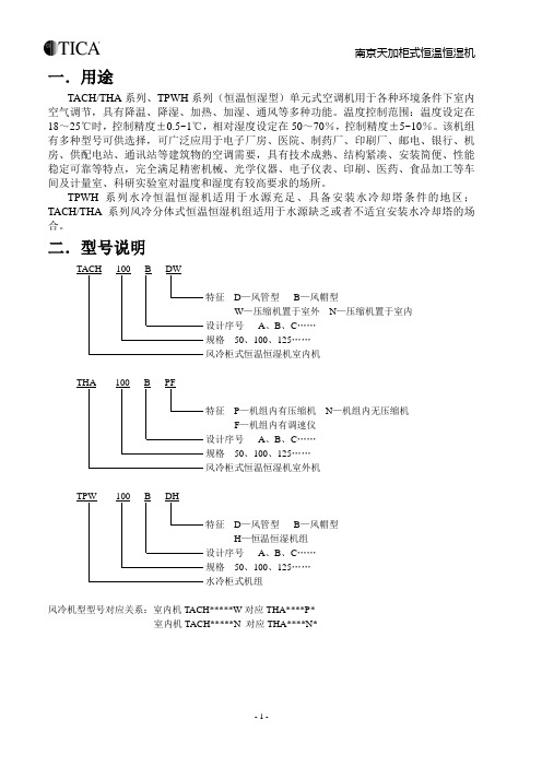
- 1 -一.用途TACH/THA 系列、TPWH 系列(恒温恒湿型)单元式空调机用于各种环境条件下室内空气调节,具有降温、降湿、加热、加湿、通风等多种功能。
温度控制范围:温度设定在18~25℃时,控制精度±0.5~1℃,相对湿度设定在50~70%,控制精度±5~10%。
该机组有多种型号可供选择,可广泛应用于电子厂房、医院、制药厂、印刷厂、邮电、银行、机房、供配电站、通讯站等建筑物的空调需要,具有技术成熟、结构紧凑、安装简便、性能稳定可靠等特点,完全满足精密机械、光学仪器、电子仪表、印刷、医药、食品加工等车间及计量室、科研实验室对温度和湿度有较高要求的场所。
TPWH 系列水冷恒温恒湿机适用于水源充足、具备安装水冷却塔条件的地区;TACH/THA 系列风冷分体式恒温恒湿机组适用于水源缺乏或者不适宜安装水冷却塔的场合。
二.型号说明D —风管型 B —风帽型W —压缩机置于室外 N —压缩机置于室内 A 、B 、C …… 50、100、125……P —机组内有压缩机 N —机组内无压缩机 F —机组内有调速仪 A 、B 、C …… 50、100、125……D —风管型 B —风帽型 H —恒温恒湿机组 A 、B 、C …… 50、100、125……风冷机型型号对应关系:室内机TACH*****W 对应THA****P*室内机TACH*****N 对应THA****N*- 2 -三. 安全注意事项◆操作机组之前,请详细阅读所有“安全注意事项”。
◆“安全注意事项”内列举各种与安全有关的重要事项,恳请严加遵守。
此标记适用于电气安装、维修等操作。
只有有经验的合格电工才能进行本系统安装不当,易造成触电事故。
✧ 要保证空调进出风畅通。
当和燃烧器具一起使用时,要特别注意。
✧ 当机组长时间不运行时,请关闭总电源。
✧ 如需冬季运行,请提前12小时上电预热。
✧ 请不要频繁转动温控开关,空调可能因频繁启动受损。
罗格朗客控系统RCU技术手册
客房状态实时显示 ·每个客房的房态实时显示和控制:出租房态、待租房态、退租房态、VIP房态、空置房态。 ·客房服务信息实时显示: “ 请勿打扰” 、“ 请即清理” “ 请稍候” “ 请求退房” “洗衣服务”等。 ·客房房门开或关状态显示和报警。 ·客房空调温度显示和控制。 ·显示插入房卡身份识别信息(识别型插卡)。 客房工作记录查询 ·当前记录查询
2
00000010
3
00000011
4
00000100
5000001016来自000001107
00000111
8
00001000
9
00001001
10
00001010
十进制 52 53 54 55 56 57 58 59 60 61 62
二进制 00110100 00110101 00110110 00110111 00111000 00111001 00111010 00111011 00111100 00111101 00111110
控制系统安装
1-简介
酒店客房控制系统 技术指导书
1.1-酒店客房控制系统简介 罗格朗酒店客房控制系统为酒店客房提供完善的解决方案:客房实时服务信息显示,客房工作记录查询,灯光控制,空调节能 管理,系统联网等功能。该系统不但能提高酒店的管理效率和服务质量,使入住客户感受更满意更舒适,而且能为酒店实现节 能管理及节约开支。
1(标间)/2(套间) 4 (max)
可用普通灯光替代 1
1(套间) 1(套间)
5
控制系统安装
3-主机
3.3-产品外观
酒店客房控制系统 技术指导书
RCU主机安装示意图
3.4-主机PCBA功能说明
大众主机说明书
大众主机说明书一、引言大众主机是一种广泛应用于家庭和办公环境的计算机设备,它是一台集中处理和管理数据的设备。
本说明书将详细介绍大众主机的功能、特点以及使用方法,旨在帮助用户更好地理解和使用大众主机。
二、功能与特点1. 数据存储:大众主机具有较大的存储容量,能够存储大量的数据文件,用户可以随时访问和管理这些数据。
2. 数据处理:大众主机拥有强大的处理能力,可以高效地处理各类数据,包括文字、图像、音频等。
3. 网络连接:大众主机支持网络连接,用户可以通过网络与其他设备进行数据传输和通信。
4. 多用户支持:大众主机可以同时支持多个用户的访问和使用,每个用户都可以独立地进行操作。
5. 多任务处理:大众主机能够同时执行多个任务,提高工作效率。
6. 安全保护:大众主机具备防火墙、数据加密等安全保护功能,确保用户数据的安全性和隐私性。
三、使用方法1. 开机与关机:按下电源按钮即可启动大众主机,关机时可通过操作系统的关机指令进行关闭。
2. 数据存储与管理:用户可以通过操作系统提供的文件管理功能对数据进行存储、复制、删除等操作。
3. 软件安装与卸载:用户可以通过操作系统提供的软件安装程序进行软件的安装和卸载。
4. 网络设置:用户可以通过操作系统提供的网络设置功能进行网络连接的配置和管理。
5. 多用户管理:大众主机支持多用户同时使用,用户可以通过操作系统提供的用户管理功能进行用户的添加、删除和权限设置。
6. 故障排除:当大众主机出现故障时,用户可以参考操作系统提供的故障排除指南进行排查和修复。
四、常见问题解答1. 为什么无法启动大众主机?可能是电源故障或者主机内部硬件故障导致,建议检查电源连接是否正常,如仍无法启动,可联系厂家售后服务。
2. 如何连接大众主机到网络?可以通过有线或无线网络连接大众主机,具体操作可参考操作系统提供的网络设置指南。
3. 如何扩展大众主机的存储容量?可以通过连接外部硬盘或使用云存储服务来扩展大众主机的存储容量。
诺基亚 Philips DVR2008 硬盘录像机用户手册说明书

PhilipsHard disk recorderDVR2008Embrace your movies, music, photoswith your very own Media CentreCreate your own jukebox of videos, music and songs, by connecting your multiple devices and sources. Take complete control your TV time and entertainment with One Touch Pause Live TV. Never miss another great TV moment again.Connect and enjoy multiple sources•HDD Media Jukebox lets you store movies, music and photos •Hi-Speed USB 2.0 Link plays video/music from USB flash drive Records and plays all your movies and music•DivX Ultra Certified for enhanced playback of DivX videos•Plays DivX, MPEG-4, MP3, WMA and JPEG digital camera photos •DivX with Chinese subtitlesEnjoy enhanced TV viewing•FlexTime to watch the beginning while you record the end •Instant Replay for reliving a live TV moment with one touch •One Touch Pause Live TV freezes the action instantly Brings audio and video to life•High definition JPEG playback for images in true resolution •Progressive Scan component video for optimized image qualityHighlightsHDD Media JukeboxCreate your very own digital media jukeboxright in your living room. Transfer MP3, WMA,MPEG2, DivX, DivX Ultra, Xvid, JPEG and HDJPEG files quickly and conveniently onto therecorder's built-in hard disk - from USBthumbdrives, portable media players, digitalcameras, and even some AV devices. Play backyour favorite movies, music or photos on yourTV or home theater system anytime you want.The options are endless, as will be theenjoyment.Hi-Speed USB 2.0 LinkThe Universal Serial Bus or USB is a protocolstandard that is conveniently used to link PCs,peripherals and consumer electronicequuipment. Hi-Speed USB devices have a datatransfer rate of up to 480 Mbps - up from the12 Mbps in original USB ones. With Hi-SpeedUSB 2.0 Link, all you have to do is plug in yourUSB device, select the movie, music or photoand play away.Instant ReplayWith Instant Replay, you can relive magicmovie moments and super sports scenes -anytime you want. At the touch of a button,the hard disk will replay the last 30 seconds.Skipping backwards further requires nothingmore than pressing the button again.One Touch Pause Live TVPause Live TV puts you in absolute control.Once the recorder is turned on, a large built-in memory automatically starts recording theprogram you are watching -- allowing you topause, replay or save the program, anytime.When you need to take a break, you can pauseyour 'live' TV program with just one touch of abutton, and resume watching when it suits you.DivX Ultra CertifiedWith DivX support, you are able to enjoyDivX encoded videos in the comfort of yourliving room. The DivX media format is anMPEG4-based video compression technologythat enables you to save large files like movies,trailers and music videos on media like CD-R/RW, and DVD recordable discs. DivX Ultracombines DivX playback with great featureslike integrated subtitles, multiple audiolanguages, multiple tracks and menus into oneconvenient file format.Plays it allPlay virtually any media format you want -whether they be DivX, MPEG-4s, MP3s, WMAor JPEGs. Experience the unbeatableconvenience of great playability, and the luxuryof sharing media files on your TV or hometheater system - in the comfort of your livingroom.Issue date 2009-11-06 Version: 1.0.512 NC: 8670 000 37609 EAN: 87 12581 40012 5© 2009 Koninklijke Philips Electronics N.V.All Rights reserved.Specifications are subject to change without notice. Trademarks are the property of Koninklijke Philips Electronics N.V. or their respective owners. SpecificationsPicture/Display•D/A converter: 10 bit, 54 MHz•Picture enhancement: Progressive Scan•A/D converter: 10 bit, 27MHzSound•D/A converter: 24 bit, 192 kHz•A/D converter: 24 bit, 96 kHzVideo Recording•Recording system: PAL•Compression formats: MPEG2•Recording Modes: High Quality (HQ), Standard Play (SP), Long Play (LP), Extended Play (EP), Super Long Play (SLP)•Audio compression: Dolby Digital, PCM •Recording Media: HDD•Recording enhancements: One Touch Record (OTR), Erase, Divide, Auto Chapter Marking, Manual Chapter MarkingVideo Playback•Playback Media: USB flash drive •Compression formats: MPEG2, MPEG1, DivX 3.11, DivX 4.x, DivX 5.x, DivX 6.0, DivX Ultra, XviD Audio Playback•Playback Media: USB flash drive •Compression format: Dolby Digital, MP3, WMA, PCMStill Picture Playback•Picture Compression Format: JPEG•Picture Enhancement: Slideshow with MP3 playback, Rotate, ZoomStorage Media•HDD recording enhancements: Pause Live TV, Instant Replay, FlexTime, Instant Jump, Time Shift Buffer •HDD Media Jukebox Capacity: up to 60 DivX movies, 8650 MP3 songs or 71000 JPEG photos at default setting•Hard Disk Capacity: 160 GB•HDD video recording capacity: 123 hrTuner/Reception/Transmission•TV system: PAL B/G, PAL D/K, PAL I Connectivity•Front / Side connections: USB 2.0•Rear Connections: Composite video (CVBS) input, Analog audio Left/Right in, Component Video input, Composite video (CVBS) output, Analog audio Left/Right out, Component Video output, RF antenna in / TV out, S-Video out Convenience•Programming/Timer Enhancements: One Touch Recording, Daily/Weekly Repeat Program, Manual Timer•Programmable Events: 8•HDD Media Jukebox: DivX, JPEG digital camera photos, MP3, WMAPower•Power supply: 220-240V, 50Hz•Power consumption: 28 W•Standby power consumption: 3W Accessories•Included Accessories: A/V Cable, Antenna cable, User Manual, Quick start guide, Remote Control, 2 x AAA Batteries, CVBS video cable, Warranty LeafletDimensions•Product weight:3 kg•Product dimensions (WxDxH): 360 x 285 x 50•Weight incl. Packaging: 4 kg。
08加密机使用手册22页word
08加密机使用手册广州江南科友科技股份有限公司范福胜2009-02-25第一章支付服务密码机简介 (3)1.1密码机的功能 (3)1.2密码机的技术特点 (3)1.3密码机的技术指标 (4)1.4密码机的外形结构 (4)第二章支付服务密码机的使用 (5)2.1密码机的配套清单 (5)2.2密码机的安装 (6)2.2.1安装步骤 (6)2.2.2密码机的初始化 (6)2.2.3注入密钥 (6)2.3密码机各部分的说明 (7)2.3.1IC卡插座 (7)2.3.2密钥销毁锁 (7)2.3.3机仓后部的锁 (7)2.3.4蜂鸣器 (7)2.4密码机的接口 (7)2.5注意事项 (8)第三章密钥管理哑终端使用说明 (9)3.1使用说明 (9)第四章加密机配置 (10)4.1设置加密机IP (10)4.2查看、添加和删除客户端IP (10)4.3设置加密常用设置 (11)4.4查看加密机IP地址、网关和子网掩码 (11)第五章超级管理员,管理员和维护权限 (12)5.1加密机权限分类 (12)5.2进入相应管理权限状态 (12)5.3超级管理员,管理员以及维护员的权限。
(12)5.3.1 超级管理员权限 (12)5.3.2 管理员权限 (12)5.3.3 维护员管理员权限 (13)5.5制作三种权限卡 (13)5.5.1 IC卡的格式化 (13)5.5.2超级管理员卡的制作 (14)4.5.3管理员权限卡的制作 (15)5.5.4维护员权限卡的制作 (15)第六章密钥注入 (17)6.1加载主密钥 (17)6.2注入IC卡密钥 (18)6.3注入功能密钥 (19)附录1 所有终端命令功能表 (20)附录2 LMK表 (22)第一章支付服务密码机简介支付服务密码机是用于银行卡网络系统的支持多进程的主机节点数据密码机,直接与主机相连接,以规定的协议通讯。
此密码机设计可靠,结构合理,使用方便,外型美观。
1.1密码机的功能支付服务密码机是金融网络安全系统的重要组成部分之一,主要的功能是实现对网络上传输的信息进行保护或鉴别,以保证金融信息的正确性,能够有效防止对通信数据的非法窃取或篡改。
pearl2008(中文说明书)

Pearl 2008Pearl Tigerፆүણ҂͘ΊEdited by Foxit Reader后面板的其它接口Qwerty(键盘接口):用于连接标准个人电脑的键盘。
可输入单步程序(memory),多步程序(chase) 和素材(palette) 的文本名称。
如果要使用键盘,应在开机前连接好。
VDU(外置显示器接口):连接外置的VGA 显示器。
所有符合VGA 标准的显示器都可用,640x480 的分辨率。
连接的VDU 显示器不能显示除控制台本身的显示之外的信息,但有些额外的显示信息可以利用,这对编程和操作复杂的演出非常有用。
Serial(串行接口):用于连接Stage Remote (舞台遥控器)或者graphics tablet模式选择转换器(Mode select keyswitch ) 设置控制台的操作模式。
Program (编程) 用于编辑演出程序,Run (运行) 用于运行演出程序,System (系统) 用于配置控制台。
预置推杆(Preset Faders ) 独立控制单通道常规灯(dimmer) 和电脑灯的光亮度。
推杆下面的2 个按键用于选择和点控灯具。
各个推杆和相应的按键被统称为“Handle”(手柄)。
总控推杆程序推杆和点控按键主显示屏控制转轮菜单软键灯具翻页按键数字键区和控制键灯具属性选择键命令按键多步程序号码和步号码多步程序进程栏转轮功能和数值Stage fixtures (舞台灯具):Stage Intensities (舞台亮度):按View (查看)键然后软键A 。
显示各个配灯推杆的光亮度(号码显示的是配灯推杆而非DMX 通道号码)。
预置推杆(Preset handles)模式转换器总控推杆程序翻页滚筒程序推杆和点控按键主显示屏控制转轮菜单软键灯具翻页按键数字键区和控制键灯具属性命令按键(相当于“shift”键) 再按下排的Swop键。
灯具翻页按键。
地址。
用户可以通过数字键区输入新的地址码。
操作手册(有线数字电视)
最新操作手册(有线数字电视)————————————————————————————————作者:————————————————————————————————日期:2有线数字电视操作手册安装阶段原来是用光盘安装。
安装完成后还需要很多配置过程。
现在采用的是用母盘Gost的方式,大大缩短了安装的时间。
但因为一套系统中,两台主机的配置略有不同。
这些配置将在调试阶段完成。
操作系统Debian的安装步骤:在下面的Debian安装流程中不再做多余的文字说明,默认调出图示界面后按下回车即可,个别必须说明之处额外再做标注。
图1:安装选择图2:语言选择图3:国家或地区选择图4:键盘布局选择图5:输入主机名称图6:输入域名图7:磁盘分区选择注意:在磁盘分区选择时一定要知道自己在做什么,以及每步操作之后的结果是什么!习惯上我喜欢使用手动分配磁盘,这样我可以自己control一切,不会outofcontrol导致硬盘数据丢失。
对于一般用户来说,分三个区即可,一个/分区,一个/home分区,一个swap 分区。
/分区类似于M$ Windows的系统分区,/home分区类似于M$ Windows除了系统分区以外的所有分区,swap分区类似于M$ Windows的虚拟内存。
一般来说,我预留1G的swap分区,10~20G的/分区,其它所有空间都留给/home分区。
如果你又有长进了,自然会知道根据自己的需求把哪些目录独立挂载,但现在这个阶段先按照我说的来好了。
图8:swap分区设定图9:/分区设定图10:/home分区设定注意:/home分区保留上次分区设定并不做格式化是为了保留用户数据--你装M$ Windows时也没有必要格式化系统分区之外的其它分区,除非是一块新的磁盘或者你不想要数据了。
图11:分区设定结束并将修改写入磁盘图12:确定将分区修改写入磁盘图13:设置root用户密码图14:创建一个新的普通用户图15:设置普通用户密码图16:开始安装基本系统注意:如果使用netinstall CD安装,只能安装出没有桌面的基本系统。
2008年Navigator和Navigator L Sync Kit用户手册说明书
2008 Navigator , Navigator L Sync Kit Manual Table of ContentsSync KIT SYSTEM INSTALLATION CONTENTSINSTALLATIONSync KitGENERAL PROCEDURESConfiguration & ProgrammingFunctional TestTroubleshootingINSTALLATIONSYNCSpecial Tool(s)Vehicle Communication Module(VCM) and IntegratedDiagnostic System softwarewith appropriate hardware.Universal Serial Bus (USB)Male-A to Male-A CableCCMUSB2-AM-AM-10 orequivalent.SYNC ComponentsReview Sync Installation Kit ContentsNOTE:Kits are not interchangeable.NOTE:Installer must have access to Professional Technicians Society (PTS) and have a valid PTS user ID and password.NOTE:Before beginning installation ensure correct operation of vehicle entertainment system.NOTE:This Sync kit only fits 2008 Navigator and Navigator L built after 12-4-2007 with Elite option package only. Elite package includes vehicle navigation and rear roof mounted DVD player.1.Review the Sync kit contents.Sync Kit ContentsQUANTITY DESCRIPTION1INSTALLATIONINSTRUCTIONS (WEBBASED)1SYNC MODULE1SYNC MAIN HARNESS1USB CABLE2TIE STRAPS 14‘‘10TIE STRAPS 8’’4.Turn the ignition key to the ‘‘OFF’’ position.1CUSTOMERINFORMATION Prepare VehiclePACKET. INCLUDESQUICK REFERENCE(ENGLISH & FRENCH)NOTE:If the vehicle does not have a rear roofAND NAVIGATION mounted DVD player, ‘‘STOP’’. Do not install thisSYSTEM SUPPLEMENT kit.(ENGLISH & FRENCH)5.Remove the Rear DVD player.Before Installing This Kit•Flip down the DVD video display andremove the 4 mounting screws.2.Turn the ignition key to the ‘‘ON’’ position.•Pull down on the sides of the DVD playerto disengage the clips from the bracket. 3.Inspect the Audio Control Module (ACM) part•Using a suitable tool, push the rear most number. If the ACM part number is notU-hook forward and release the U-hooks.8L7T-18K931-DA, ‘‘STOP’’. Do not install this•Hang the DVD player on the J-hooks and kit. To check the ACM part number:disconnect the electrical connector.•Press the ‘‘Menu’’ button on the ACM.•Remove the DVD player from the J-hooks.•Touch the ‘‘System Info’’ button on theACM screen.•ACM part number is located on the displayafter HW:•ACM part number must be:8L7T-18K931-DA.NOTICE:Use extreme care in releasing the wireterminals from the connector. Lifting theterminal release more than 1mm could result inconnector damage.ing a small pick or equivalent lift theterminal release no more then 1mm to releasethe wires with the terminals.6.Snip the DVD connector tie strap and unwrapwire tape.9.Repin green/orange wire located in cavity 5:•Remove green/orange wire from cavity 5.•Insert green/orange wire into cavity 4.10.Repin blue/brown wire located in cavity 6:•Remove blue/brown wire from cavity 6. 7.Remove the connector cover.•Insert blue/brown wire into cavity 3.•Using a small pick or equivalent, slightly11.Repin violet/brown wire located in cavity 21:spread the end of the outer connector coverto release it from the connector before•Remove violet/brown wire from cavity 21.sliding.•Insert violet/brown wire into cavity 20.•Slide the cover from the connector.12.Repin yellow/blue wire located in cavity 22:•Remove yellow/blue wire from cavity 22.•Insert yellow/blue wire into cavity 19.13.Install the connector cover.24.Remove the front floor console finish panel.•Slide the cover onto the connector.•Open the floor console storage door.•Secure with 8‘‘tie strap.•Lift upward on the rear of the floor console finish panel to release the floor console 14.Hang the DVD player on the J-hooks.finish panel clips.15.Connect the electrical connector.16.Remove the DVD player from the J-hooks.17.Tilt the DVD player, as necessary, to align itcorrectly.18.Align the left side guide pin with the left sidelocating hole.19.Lift up the right side of the DVD player andengage the U-hooks.20.Push on the left and right sides of the DVDplayer to engage the clips.NOTICE:Use extreme care not to contact the ACM navigation display screen when removing 21.Install the 4 mounting screws.the ACM and the instrument panel center finish panel. Unintended contact with the display screen 22.Turn the ignition key to the ’’ON‘‘ position.can easily scratch and otherwise damage the Apply the parking brake and move the shift display.lever to ’’NEUTRAL‘‘.25.Remove the instrument panel center finish•Turn the ignition key to the ’’OFF‘‘panel.position.•Remove the 2 instrument panel center finish 23.Remove the shifter trim ring.panel screws.•Pull outward on the panel to disengage the clips.•Disconnect the electrical connectors.28.Release the stops and lower the glovecompartment.26.Remove the 4 screws and the Audio ControlModule (ACM).•Disconnect the electrical connectors, theantenna cable connector, and the global Install USB Cable Assemblypositioning system (GPS) antenna.•Remove the ACM.NOTE:USB Cable Assembly will be connected tothe Sync module later in this procedure.29.Locate and drill 3/4’’ (19mm) hole in the frontof the console box below the Auxiliary audioInput Jack.30.Install the USB cable assembly.•Route through the hole as shown.•Secure the grommet.27.Open the glove compartment.•Disconnect the dampener.31.Disengage the green electrical connectormounting clip and position connector aside.34.NOTE:Avoid routing the Sync wires nearsharp edges and moving components.NOTE:Ensure the Sync wires are secure anddo not interfere with vehicle operation.Start at the ACM opening and route the DLCtakeout of the Sync harness from the ACM areato the driver footwell area.32.Route the USB cable through the opening nextto the green electrical connector, up behind thecenter stack panel and out the glove boxopening.35.Connect the Sync male DLC connector to thevehicle female DLC connector and secure theconnection using (2) 8‘‘ tie straps through opencavities of the connectors.Install Sync Wire Harness33.Remove the 2 screws at the Data LinkConnector (DLC).36.NOTE:Ensure the Sync wires are secure anddo not interfere with vehicle operation.Install the Sync wire harness female DLC to thevehicle DLC mounting location.•Install the 2 screws.•Secure DLC connector and excess harnessunder instrument panel.39.Reposition the green electrical connector andsecure to the mounting clip.40.Route the 54-way module connector from theACM opening to the glove compartmentopening.37.Disconnect the black 10-way connectorseparating the Sync jumper harness from themain Sync harness.41.Connect the Sync harness 16-way ACMconnector to the vehicle 16-way ACMconnector.38.Route the female black 10-way connectortakeout from the ACM opening down behindthe center stack panel and out next to the greenelectrical connector.42.Locate and disconnect the 42-way connectorC314 located in the center console. Theconnector is located to the right of the shiftlever.REMOVAL AND INSTALLATION(Continued)NOTE:Connector view is wire end view.43.Remove the connector wire cover.44.Remove the red terminal lock between cavity46.Remove the red terminal lock from the Syncnumbers 28-42.jumper harness male black 10-way connector.45.Release the following 5 wires.47.Insert the following 5 vehicle wires removed•Orange wire located in cavity 39.from connector C314 into the Sync jumper •Green/orange wire located in cavity 40.harness male black 10-way connector.•Blue/brown wire located in cavity 41.•Insert the yellow/blue wire into the male •Violet/brown wire located in cavity 32.black 10-way connector cavity 1.•Yellow/blue wire located in cavity 33.•Insert the violet/brown wire into the maleblack 10-way connector cavity 2.•Insert the blue/brown wire into the maleblack 10-way connector cavity 3.•Insert the green/orange wire into the maleblack 10-way connector cavity 4.•Insert the orange wire into the male black10-way connector cavity 5.NOTE:Connector view is the wire end view of the50.Re-install the red terminal lock.Sync jumper harness male black 10-way connector.51.Re-install C314 connector cover and re-connect.•Tighten to 3Nm (27 lb-in).52.Connect the Sync jumper male harness black10-way connector to the main Sync harnessfemale black 10-way connector.48.Install the red terminal lock to the Sync jumperharness male black 10-way connector.49.Insert the five terminals provided with the SyncJumper harness into connector C314 as follows:•Bare wire into cavity 39.Install Module•Blue wire into cavity 40.•Gray/orange wire into cavity 41.NOTE:Before connecting Sync harness to the Sync •Violet/green wire into cavity 32.module, make sure the connector lock lever ispositioned forward away from the connector wires •Brown/white wire into cavity 33.in the full release position.NOTE:Connector view is wire end view.53.Working through the glove compartmentopening plug the Sync 54-way connector intothe Sync module and the USB cable into theblack USB port on the Sync module.54.Position the Sync module inside the bracingbetween the glove compartment and the centerstack.ing (2) 14’’ tie straps, secure the Syncmodule to the bracing between the glovecompartment and the center stack.Install TrimNOTE:View looking through the glovecompartment openingNOTE:Ensure the Sync wires are secure and donot interfere with vehicle operation.e the supplied 8‘‘ tie wraps to secure theSync harness wires.60.Install the instrument panel finish panel.•Connect the electrical connectors.•Push inward on the panel to engage theclips.•Install the instrument panel finish panelscrews.61.Install the front floor console finish panel. 56.Install the audio ACM and the 4 mounting•Close the floor console storage door.screws.62.Install the shifter trim ring.•Connect the electrical connectors, the16-way Sync wire harness connector, the63.With the parking brake applied turn the ignitionantenna cable connector, and the globalkey to the ’’ON‘‘ position.positioning system (GPS) antenna.64.Move the shift lever to ’’PARK‘‘. Configuration, Programming and FunctionTest•Turn ignition key to the ’’OFF‘‘ position.•Release the park brake.57.Refer to the Sync configuration andprogramming section (click here).65.Connect the glove box dampener.58.Refer to the Sync functional test section (click66.Close the glove compartment.here).INSTALLATION(Continued)Sync Module Configuration & ProgrammingNOTE:To complete the Sync kit installationprocedure, the Sync module MUST be configuredand programmed to the latest released software.Also, the ACM MUST be configured properly.NOTE:Configuration and programming requiresthe use of a special PTS application. Installer unch IDS tool.have access to PTS and have a valid PTS user IDand password.9.From the Vehicle Service Session screen, Selectthe ‘‘Upgrade/Mods’’ tab.NOTE:IDS software must be at level B 53.6 P14or higher.1.Connect the VCM to the data link connector(DLC).2.Connect the VCM to the IDS tool or laptoprunning IDS software.3.Turn the ignition key to the ‘‘ON’’ position.unch IDS tool.5.If required update the VCM with the latestsoftware.10.Select ‘‘Sync Accessory Installation - 20086.Close the IDS tool.Navigator ONLY’’ link.7.From the technician service publication site•Press ‘‘Read From Vehicle ’’ button.(PTS), run OASIS using Quick Start.•Press the ‘‘Quick Start’’ button.•After Vehicle communication is establishedPress the ‘‘Get OASIS’’ button.11.Follow the on-screen instructions to completethe Radio (ACM) configuration.INSTALLATION(Continued)12.Select OK to program the APIM (Sync15.NOTE:You must use a Male-A to Male-Amodule).USB cable to complete this step.NOTE:Do not disconnect the VCM or USBcables during APIM programming.NOTE:The system may prompt you to installsoftware for the USB port. Follow the onscreen instructions to install the USB portdriver already included in windows XP.Program both processors on the Sync module(VIP & CIP).•Connect the Male-A to Male-A USB cableto the IDS tool, or laptop running IDSsoftware, and to the vehicle USB port.•Follow the on-screen instructions to programboth processors on the Sync module (VIP &CIP).13.Select the ‘‘Read APIM’’ button.16.If CIP programming failed due to USB port not 14.Press OK to message related to APIM not yetready, repeat step 15.configured or not in Ford database.17.At the end of the configuration andprogramming procedure the ‘‘Programming hasbeen completed successfully’’ screen will bedisplayed.2008 Navigator, Navigator L Sync Kit PAGE 14 INSTALLATION(Continued)18.Exit PTS.•Disconnect the VCM.•Disconnect the USB cable.Functional TestNOTE:Due to system limitation, satellite radio,line in audio and USB audio cannot be accessedthrough the DVD headphones.19.Press buttons 3 & 6 on the ACM at the sametime to activate self test. Verify all speakers arefunctioning.22.From the DTC screen, document DTC’s ifnecessary, then select ‘‘Clear DTCs’’20.Press the ‘‘End Test’’ button on the screen toexit the speaker walk test.23.The DTC’s are cleared and the user is returnedto the diagnostics menu pick screen, select‘‘Exit Diagnostics’’.21.Select ‘‘View DTCs’’.Functional Test using Rotunda Tool105-00120 Multi-Media Interface Tester (MIT)24.Turn the audio ACM ‘‘ON’’ and ‘‘SELECT’’ alocal radio broadcast station.25.Adjust the audio ACM volume to an audible29.Test the Sync USB function using the MITB test output.•Press the ‘‘TEST SELECTOR’’ button on NOTE:The MIT is powered by the USB cable.the MIT until the USB test output led isilluminated.26.Connect the MIT.•Connect the MIT USB cable to the vehicle30.Set the audio ACM input source to USB.USB port.•Press the ‘‘SOURCE’’ button on the ACM •Connect the MIT audio cable to the vehicle display until USB is displayed.audio port.•The test message ‘‘The USB audio testusing the Sync input test tool is working 27.Set the audio ACM input source to line in.correctly’’ should be heard repeating •Select the ‘‘USER DEVICE’’ button on the through the audio ACM speakers.ACM display.31.Test the Sync bluetooth function using the MIT•Press the ‘‘SOURCE’’ button on the ACMbluetooth test output.display until line in is displayed.•Press the ‘‘TEST SELECTOR’’ button onthe MIT until the bluetooth test output led isilluminated.32.Place the audio ACM in the discovery mode.•Press the ‘‘BT DEVICES’’ button on theACM display.•Select the ‘‘ADD’’ button from the nextdisplay screen.•The ACM will display a six digit pass keywith the audio message ‘‘Search for Syncon your device and enter the pass keyprovided by Sync.’’ through the audio ACMspeakers.NOTE:Audio level is lower than the pre-setvolume.28.Test the Sync Line in function using the MITaux test output.•Press the ‘‘TEST SELECTOR’’ button onthe MIT until the aux test output led isilluminated.•Increase the audio level on the ACM.•The test message ‘‘The audio input jack testusing the Sync input test tool is workingcorrectly’’ should be heard repeatingthrough the audio ACM speakers.33.Enter the six digit pass key number into the35.Remove the bluetooth device from the audioMIT.ACM.•Press and hold the ‘‘PAIR’’ button until the•Select the ‘‘MEDIA’’ button on the ACM.three test mode LEDs illuminate.•Select the ‘‘BT DEVICES’’ button on the •Release the ‘‘PAIR’’ button. The Aux test audio ACM display.LED will illuminate.•Select the ‘‘Free2move WA Connected’’•Enter the first digit of the pass key by button on the audio ACM display. .pressing the ‘‘PAIR’’ button on the MIT the•Select the ‘‘Delete’’ button on the audionumber of times equal to the first number of ACM display.the six digit pass key. If the number is ‘‘0’’•Select ‘‘YES’’ to confirm button on the do not press the PAIR button. Press theaudio ACM display.‘‘TEST SELECTOR’’ button to confirm the•Select ‘‘RETURN’’ button on the audio entry.ACM display to return to the main display.•Enter the second digit of the pass key bypressing the ‘‘PAIR’’ button on the MIT the36.Turn the ignition key to the ‘‘OFF’’ position.number of times equal to the second numberof the six digit pass key. Press ‘‘TEST37.If multi media interface tester is not available,SELECTOR’’ button to confirm the entry.Sync bluetooth functionality can be verified by Continue until all six numbers of the passpressing the phone button on the ACM. A key have been entered.message stating ‘‘No Phone Connected’’ must •Once all six pass key digits have been be displayed on the ACM screen. USB port entered the MIT will flash the bluetooth test functionality can be verified using any USB selector led indicating the pairing is in media device (IPod, MP3 player, or a memory process. Pairing is complete when the audio stick) with audio files. Line-in audioACM plays an audio warning and displays functionality can be verified using the same‘‘Free2move WA Connected.’’media device.38.NOTE:The vehicle must be outside in order toreceive satellite radio and GPS signals.NOTE:The satellite radio must be activated inorder to test this functionality.Verify audio output of the satellite radiothrough each speaker.39.Verify the correct operation of the navigationsystem.40.Verify the correct operation of the DVD playersystem.41.Verify steering wheel controls are functioning 34.Disconnect the MIT tool.properly.。
主机说明书_20140507
主机软件页面配置指南目录主机软件页面配置指南 (1)一连接方式 (1)二页面配置 (2)三注意事项 (11)一连接方式1.将主机接入网络,电脑可以以有线或无线的方式与主机相连,如下图:无线SSID(默认2.4G):LINKING_XXXXXX;无线密码:xxxxxxxx,可参考主机背后标签;2.PC端采用DHCP方式从主机获取IP地址,主机默认管理页面IP地址为192.168.16.251,输入默认用户名和密码:admin/admin,即可成功登录主机配置页面;注意:WAN口与LAN口请勿在同一网段中,不然会导致网络异常。
例如:WAN口是上位机DHCP分出的192.168.16.1,LAN口应分配其他网段地址,如192.168.3.X 。
二页面配置1.状态:查看设备状态的基本信息和无线信息;2.网络1)网络->WAN:支持DHCP自动获取、Static IP和PPPoE三种方式,系统默认为DHCP 方式:2)网络->LAN:修改LAN IP地址、地址池、租约时间3)网络->2.4G和5G:设定用户自定义无线参数:注意:部分型号的主机才支持5G功能。
3.文件管理:1)文件-本地:可格式化内置硬盘,可配置内置硬盘分区大小等;注意:初始化硬盘时时间较长,请耐心等待页面跳转,否则可能导致内置硬盘损坏;2)文件->本地->配置,可重新对my_data和Camera_his划分硬盘大小,注意大小设置中输入的值必须为4的倍数;3) 文件->本地->示意图,可更加直观查看当前内置硬盘的使用情况;4) 文件->外设:可查看USB外置硬盘的分区信息、示意图,退出外置USB外置硬盘;内网PC可通过访问网上邻居\\192.168.16.251\data\usb_xxx进行读取USB外置硬盘中的文件。
4.下载:下载功能支持BT种子下载,可控制下载速度,支持新建、开始、停止,默认下载路径为\\192.168.16.251\data\hdd\bt;1)点击新建,可从本地或远程添加BT种子资源:2)点击配置,可修改下载路径、下载速度等参数;5.智能家居:可注册主机账户,可设置保存摄像头的分辨率和保存天数;6.设置:可修改系统登录密码、可重启、复位、关闭设备,可进行页面升级;软件页面升级,注意事项:1.升级前后需确定版本信息,选择文件时一定要选择指定的版本;2.升级过程中不要断电、关机等其他操作;3.最好选择使用有线方式连接设备,通过PC端IE浏览器进行页面升级;7.高级:1)高级->WebDav设置,可启用/禁用该服务,在手持客户端可通过WebDav工具对主机设备内置或外置USB硬盘进行文件管理,读取、写入、删除等;2)高级->Samba管理,可启用/禁用该服务,默认登录用户名和密码为admin/admin,可修改密码保护方式:取消密码保护、用户自定义、与登录密码保持一致;可修改工作组和主机名(可用主机名直接访问Samba,如:\\SmartHome)3)高级->防火墙:允许Internet访问内网指定的PC端IP地址,内网PC开放ftp、http 等服务;4)高级->时间,可同步Internet时间,同时亦可同步本地PC的时间;5)高级->其他:可进行UPNP和DLNA功能的设置,启用/禁用该服务,修改服务显示的名称等;8.其他:在页面中可切换页面显示语言,点击X可退出登录页面;左下角可快速关机设备;三注意事项1、WAN口与LAN口设置请勿在同一网段中,不然会导致网络异常。
PR2008-C型视频传输发射接收模块解析
PR2008-C型视频传输发射接收模块---------信号传输的革命, 省钱就是赚钱1、功能特点1.1通过两个模块,一个发射模块,一个接收模块,实现视频信号的加权放大、平衡衰减等功能,从而实现高质量的远程视频信号传输。
1.2由于采用放大处理的信号进行传输,对于线间干扰、电源干扰,有明显抑制和降低作用。
1.3采用集成模块封装形式,体积小,使用灵活方便,可靠性高。
2、产品优势2.1适应性广:此模块适合与同轴电缆、双绞线电缆等多种线缆的视频信号传输。
2.2使用此模块可以带来4个明显效果。
一是同样电缆可以提高3倍左右的传输距离,二是画面的细节明显清晰、色彩饱满,三是画面干扰条纹明显减少,画质更干净,四是可以通过降低线材和摄像机的选型档次达到同样的视觉效果而减少工程的总造价进而赢得更大利润。
2.3采用贴片电路及模块化设计和挡死的价格定位,使该产品更具实用性和普及性。
3、使用报告3.1使用800米75-3的同轴电缆线,直接传输发现细节和色饱合度明显变差,使用该产品后和本地传输的效果用肉眼观察没有明显区别。
3.2使用1000米双绞线,直接传输发现细节和色饱合度明显变差,有明显干扰条纹,使用该产品后和本地传输的效果用肉眼观察没有明显区别。
4、使用方法接线说明:1电源正(12V ,可以和摄像机共用电源)2视频信号输入(接摄像机输出信号)3视频信号输出(通过电缆连接接收模块视频输入端7)4电源负同时为视频信号接地端5视频信号输出(接监视器视频输入信号)6视频信号接地端7视频信号输入端(接发射模块视频输出端3)8 视频信号接地端5、视频模块使用现场示意图作者:石家庄市爵程工贸公司王小鹏欢迎发邮件到WXP@和作者交流互动。