万和燃气采暖热水炉L1GB20说明书
壁挂式燃气采暖热水炉使用说明

壁挂式燃气采暖热水炉使用说明一、安装前准备1.选择安装位置壁挂式燃气采暖热水炉应安装在通风良好的室内,远离易燃易爆物品,以确保安全使用。
需选择水源、燃气管道和排烟管道的合适位置,确保连接方便。
2.安装前检查在安装壁挂式燃气采暖热水炉前,需要仔细检查产品包装,确认所有配件齐全,无损坏情况。
应对安装位置进行测量,确保大小合适。
3.选择安装时间安装壁挂式燃气采暖热水炉时,需选择在气温较低的季节进行,避免在采暖季节使用高峰期出现安装延误的情况。
二、安装步骤1.固定壁挂式燃气采暖热水炉在已选择的安装位置,用螺丝将壁挂式燃气采暖热水炉固定在墙壁上,确保牢固稳定。
2.连接水源和燃气管道将壁挂式燃气采暖热水炉与水源和燃气管道连接,确保管道安全,不漏水、不漏气。
3.连接排烟管道将壁挂式燃气采暖热水炉排烟口与排烟管道连接,排烟管道需要畅通无阻,确保烟气能够顺利排出。
4.接通电源将壁挂式燃气采暖热水炉的电源线接通,确保电路连接正确稳定。
5.检查安装情况安装完成后,需对壁挂式燃气采暖热水炉的各项连接进行检查,确保安装正确无误。
三、使用注意事项1.投入使用前检查在投入使用壁挂式燃气采暖热水炉前,需要仔细检查安装情况,确保所有连接牢固稳定,无泄漏情况。
2.正确使用温控器根据室内温度情况,合理设置壁挂式燃气采暖热水炉的温控器,避免出现温度过高或过低的情况。
3.定期清洁保养定期对壁挂式燃气采暖热水炉进行清洁保养,确保热水炉正常运行,延长使用寿命。
4.避免堵塞排烟管道在使用壁挂式燃气采暖热水炉时,需要定期清理排烟管道,避免灰尘和杂物堵塞,影响烟气排放。
5.注意安全防护使用壁挂式燃气采暖热水炉时,需注意安全防护,避免触电、燃气泄漏、烟气中毒等危险情况发生。
四、故障处理1.燃烧不正常如果发现壁挂式燃气采暖热水炉燃烧不正常,应立即关闭燃气阀门,停止使用,并通联专业人员进行排查。
2.热水不热当壁挂式燃气采暖热水炉出现热水不热的情况时,需检查温控器设置是否正确,以及热水炉是否正常运行。
燃气壁挂式暖气器产品说明书
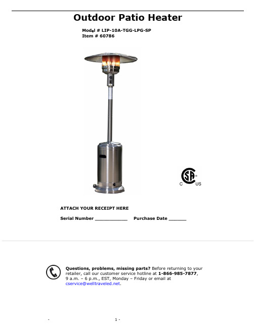
Outdoor Patio HeaterMod e l # LIP-10A-TGG-LPG-SP Item # 60786ATTACH YOUR RECEIPT HERESerial Number ___________ Purchase Date ______Questions, problems, missing parts? Before returning to your retailer, call our customer service hotline at 1-866-985-7877, 9 a.m. – 6 p.m., EST, Monday – Friday or email at *************************.SAFETY INFORMATIONSAFETY INFORMATIONPlease read and understand this entire manual before attempting to assemble, operate or install this appliance. If you have any questions regarding the product, please call customer service 1-866-985-7877, 9 a.m. –6 p.m., EST, Monday – Friday.This manual contains important information about the assembly, operation and maintenance of this patio heater. General safety information is presented in the first few pages and is also located throughout this manual. Keep this manual for future reference and to educate new users of this appliance. This manual should be read in conjunction with the labeling on the appliance. Safety precautions are essential when any mechanical or propane fueled equipment is involved. These precautions are necessary when using, storing, and servicing. Using this appliance with the respect and caution demanded will reduce the possibilities of personal injury or property damage. The following symbols shown below are used extensively throughout this manual. Always heed these precautions, as they are essential when using any mechanical or propane fueled equipment.PREPARATIONBefore beginning assembly of this appliance, make sure all parts are present. Compare all parts with package contents list and hardware contents as listed on pages 2 and 3 of this manual. If any part is missing or damaged, do not attempt to assemble this product. Contact customer service for replacement parts.ESTIMATED ASSEMBLY TIME: 60 minutesTools Required for Assembly (NOT included):Phillips screwdriver w/medium bladeLeak Detection SolutionAdjustable wrench (2) (Note: 10mm wrench or socket should fit M6 bolt; 13mm wrench or socket should fit M8 bolt.)ASSEMBLY1. Attach Wheel Assembly (K) to Base (J). Align holes in Wheel Assembly with corresponding holes in Base, and insert 2 M8x16 (AA) bolts through holesand finger tighten. Tighten with wrench once both bolts have been inserted. Hardware Used: 2 x AA, Bolt M8x162. Attach the Post Supports (I) to the Base (J). Align the holes in thebottom of each Post Support with the holes on the Base.Insert 1 M8x16 (AA) bolt through the hole in the support and into theBase and hand tighten. Repeat with the other 2 Post Supports andthen tighten all bolts with a wrench.Hardware Used: 3 x AA, Bolt M8x163.Attach the Lower Post (H) to the Post Supports (I). Once youhave tightened the bolts holding the Post Supports (I) to the Base (J),align the holes in the Lower Post (H) with the holes on the topsof the Post Supports (I) and insert a M6x35 (BB) bolt through a M6 (GG)washer and then through the hole in the Post Support. Affix anotherM6 (GG) washer onto the bottom of the M6x35 (BB) bolt and secure with aM6 (CC) nut. Repeat this in the 5 remaining holes (6 holes total—2 foreach Post Support piece). Hand tighten initially then tighten with awrench when all bolts have been inserted.Hardware Used: 6 x BB, Bolt M6x3512 x GG, Washer M66 x CC, Nut M61234. Attach Upper Post (F) to Lower Post (H) by screwing the two pieces of the posttogether.5. Place Tank Housing (D) onto Base (J). Slide Tank Housing (D) over the assembled Upper/Lower Post and down over the Post Supports. Rest Tank Housing on Base.6. Attach Head Assembly (C) to Upper Post (F).Note: There is a small piece of protective foam located in the neck of the Head Assembly that MUST be removed prior to attaching Head Assembly to the Upper Post.Route Gas Hose (E) down into Upper/Lower post assembly and align 4 small holes on Head Assembly with 4 Small holes in Upper Post(F).[HINT: Control knob should be above decal on post.]Insert 4 M6x10 (EE) bolts through 4 M6 lock washers into holes and tighten.Hardware Used : 4 x EE, Bolt M6x10 and Lock Washer M64 567. Panels (A) come packaged in two brown boxes with two panels in each box. Hardware for assembly is already affixed to each panel. Place two panels side by side and remove the two cap nuts and washers that are affixed to one panel. Insert the affixed bolts into the open holes on the adjacent panel. Place the washer over the bolt and screw on cap nut. Repeat these steps until all four panels are assembled. Then locate the Reflector Center Cap (B). You will need to remove the cap nuts and washers located at the top of each Reflector Panel to allow assembly of the Center Cap on each panel. Align the holes in the Center Cap with the bolts on each panel and affix washer and cap nut to complete assembly.8.assembled Hardware Used : 3 x DD, Wing Nut M89. Tank Housing.NOTE7 98A minimum supply pressure of .5 psi is required for the purpose of input adjustment of propane gas. Storage of an appliance indoors is permissible only if the cylinder is disconnected and removed from the appliance. A cylinder must be stored outdoors in a well-ventilated area out of the reach of children. A disconnected cylinder must have dust caps tightly installed and must not be stored in a building, garage, or any other enclosed area. The minimum permissible gas supply pressure of 11 W.C. is required for purpose of hose adjustment. The minimum hourly of 17,500 BTU is required input rating for a heater for automatic operation rating less than full input rating.The pressure regulator and hose assembly supplied with the appliance must be used.The installation must conform with local codes, or in the absence of local codes, with national fuel gas code, ANSI Z223.1/NFPA54, natural gas and propane Installation Code, CSA B149.1, or propane storage and handling code, B149.2A dented rusted or damaged propane cylinder may be hazardous and should be checked by your local cylinder supplier. Never use a propane cylinder with a damaged valve connection.The propane cylinder must be constructed and marked in accordance with the specifications for LP gas cylinders of the U.S. Department of Transportation (DOT) or the standard for cylinders, spheres and tubes for transportation of dangerous goods and commission, CAN/CSA-B339.The cylinder must have a listed overfilling prevention device.The cylinder must have a connection device compatible with the connection for the appliance.The cylinder used must include a collar to protect the cylinder valve.Never connect an unregulated propane cylinder to the heater.OPERATING INSTRUCTIONSLeak Check1. Make 2-3 oz. of leak check solution (one part liquid dishwashing detergent and three parts water).2. Apply several drops of solution where hose attaches to regulator.3. Apply several drops of solution where regulator connects to cylinder.4. Make sure all patio heater valves are OFF.5. Turn cylinder valve ON.IF BUBBLES APPEAR AT ANY CONNECTION, THERE IS A LEAK.1. Turn cylinder valve OFF.2. If leak is detected at hose/regulator connection, tighten connection and perform another leak test. If bubbles continue to appear, call our customer service hotline at 1-866-985-7877, 9 a.m. – 6 p.m., EST, Monday – Friday.check. If you continue to see bubbles after several attempts, cylinder valve is defective. Call our customer service hotline at 1-866-985-7877, 9 a.m. – 6 p.m., EST, Monday – FridayIF NO BUBBLES APPEAR AT ANY CONNECTION, THE CONNECTIONS ARE SECURE.Note: Whenever gas connections are loosened or removed, you must perform a complete leak check.Caution: Do not attempt to operate this appliance until you have read and understand all Safety Information in this manual and all assembly is complete and leak checks have been performed.Before Turning Gas Supply ON :1. Your heater was designed and approved for OUTDOOR use only. Do NOT use it inside a building, garage, or any other enclosed area.2. Make sure surrounding areas are free of combustible materials, gasoline, and other flammable vapors or liquids.3. Ensure that there is no obstruction to air ventilation. Be sure all gas connections are tight and there are no leaks.4. Be sure the cylinder cover is clear of debris. Be sure any component removed during assembly or servicing is replaced and fastened prior to starting.Before Lighting :1. Heater should be thoroughly inspected before each use, and by a qualified service person at least annually. If re-lighting a hot heater, always wait at least 5 minutes.2. Inspect the hose assembly for evidence of excessive abrasion, cuts, or wear. Suspected areas should be leak tested. If the hose leaks, it must be replaced prior to operation. Only use the replacement hose assembly specified by the manufacturer.Lighting :NOTE : For initial start or after any cylinder change, hold the control knob in for 2 minutes to purge air from all gas lines before proceeding.1. Turn the control knob to the “OFF” position.2. Fully open the LP cylinder valve.3. Turn the control knob half way between the small flame and the large flame symbols.4. Push control knob in and then push the RED igniter button to ignite the main burner. Repeat until the burner ignites. Keep the control knob fully pushed in for an additional 30 seconds after the burner ignites, then release the control knob.5. To increase the flame, turn the control knob clockwise toward the large flame symbol. To decrease the flame, turn the control know counter clockwise towards the small flame symbol.6. To turn the appliance OFF, push down the Control knob and turn clockwise to the OFF position.7. Wait at least 5 minutes before attempting to re-light the heater.8. Turn the gas cylinder valve to OFF or closed.If you experience any ignition problems, please consult “Troubleshooting” on page 13.Caution : Avoid inhaling fumes emitted from the heater’s first use. Smoke and odor from the burning of oils used in the manufacturing will appear. Both smoke and odor will dissipate after approximately 30 minutes. The heater should NOT produce thick black smoke.When Heater is ON:Emitter screen will become bright red due to intense heat. The color is more visible at night. Burner will display tongues of blue and yellow flame. These flames should not be yellow or produce thick black smoke, indicating an obstruction of airflow through the burners. The flame should be blue with straight yellow tops. If excessive yellow flame is detected, turn off heater and consult “Troubleshooting” on p age 13.Re-Lighting:Note: For your safety, control knob cannot be turned OFF without first depressing the control knob and then rotating to OFF.1. Turn control knob to OFF.2. Wait at least 5 minutes to allow gas to dissipate before re-lighting.3. Repe at the “Lighting” steps listed on page 10.Shut Down:1. Turn control knob clockwise to OFF while depressing the knob.(Normally, burner will make a slight popping noise when extinguished).2. Turn cylinder valve clockwise to OFF and disconnect regulator when heater is not in use.NOTE: After use, some discoloration of the emitter screen is normal.Operation Checklist:For a safe and pleasurable heating experience, perform this check before each use:Before Operating:1. I am familiar with entire ow ner’s manual and understand all precautions noted.2. All components are properly assembled, intact and operable.3. No alterations have been made.4. All gas connections are secure and do not leak.5. Wind velocity is below 10 mph.6. Unit will operate at reduced efficiency below 40 degrees F.7. Heater is for use outdoors (outside any enclosure).8. There is adequate fresh air ventilation.9. Heater is away from gasoline or other flammable liquids or vapors.10. Heater is away from windows, air intake openings, sprinklers and other water sources.11. Heater is at least 36 in. on top and at least 24 in. on sides from combustible materials.12. Heater is on a hard and level surface.13. There are no signs of spider or insect nests in heater orifices.14. All burner passages are clear.15. All air circulation passages are clear.16. Children and adults should be alerted to the hazards of high surface temperatures and should stay away to avoid burns or clothing ignition.17. Young children should be carefully supervised when they are in the area of the heater.18. Clothing or other protective material should not be hung from the heater, or placed on or near the heater.19. Any guard or other protective device removed for servicing the heater must be replaced prior to operating the heater.20. Installation and repair should be done by a qualified service person. The heater should be inspected before each use and at least annually by a qualified service person.21. More frequent cleaning may be required as necessary. It is imperative that control compartment burner and circulating air passageways of the heater be kept clean and free of debris and/or spider or insect nests.After Operation :1. Gas control knob is in OFF position.2. Gas tank valve is OFF.3. Disconnect gas line.To enjoy years of outstanding performance from your heater, make sure you perform the following maintenance activities on a regular basis:Keep exterior surfaces clean .1. Use soapy water for cleaning. Never use flammable or corrosive cleaning agents.2. While cleaning your unit, be sure to keep the area around the burner and control compartment dry at all times. Do not submerge the control valve assembly. If the gas control is submerged in water, do NOT use it. It must be replaced.3. Air flow must be unobstructed. Keep controls, burner, and circulating air passageways clean. Signs of possible blockage include:∙ Gas odor with extreme yellow tipping of flame. ∙ Heater does NOT reach the desired temperature. ∙ Heater glow is excessively uneven. ∙ Heater makes popping noise.∙ Spiders and insects can nest in burner or orifices. This dangerous condition can damage heater andrender it unsafe for use. Clean burner holes by using a heavy-duty pipe cleaner. Compressed air may help clear away smaller particles.∙ Carbon deposits may create a fire hazard. Clean dome and burner screen with warm soapy water if anycarbon deposits develop.Note : In a salt-air environment (such as near an ocean), corrosion occurs more quickly than normal. Frequently check for corroded areas and repair them promptly.TIP (FOR STAINLESS STEEL MODELS):Use high-quality automobile wax to help maintain the appearance of your heater. Apply to exterior surfaces from the post down. DO NOT apply to emitter screen or domes.Storage :Between uses:∙ Turn Control Knob OFF. ∙ Disconnect LP source.∙ Store heater upright in an area sheltered from direct contact with inclement weather (such as rain, sleet,hail, snow, dust and debris).∙ If desired, cover heater to protect exterior surfaces and to help prevent build-up in air passages. Neverleave LP cylinder exposed to direct sunlight or excessive heat.Note : Wait until heater is cool before covering .Service :Only a qualified service person should repair gas passages and associated components.Caution : Always allow heater to cool before attempting service.CARE AND MAINTENANCEIf you have any questions regarding this product, please call our customer service hotline at 1-866-985-7877, 9a.m. – 6 p.m. (EST), Monday – Friday, or email us at *************************.1 YEAR LIMITED WARRANTY – Customers in the Continental USAll components are warranted for a period of 1 year after date of purchase by the original owner against defects in materials and workmanship under normal use. This warranty does NOT cover normal wear and weathering, assembly and/or maintenance OR use in a commercial application if model is not designat ed as a commercial model. At Well Traveled Living’s sole discretion, products under warranty will be repaired and/or replaced at no charge to the customer. Any returns sent back to Well Traveled Living must be sent via prepaid freight and in the original retail packaging.For warranty service contact Well Traveled Living at the address, phone numbers or internet site and email listed in this owner’s manual. Be sure to have your sales receipt, date of purchase and catalogue/model numbers available when cal ling. All warranty service will be coordinated by the Well Traveled Living’s, Amelia Island, Florida service center.This warranty is extended only to the original purchaser. Proof of purchase will be required before warranty service is rendered. The sales receipt is the only valid proof of purchase. This warranty only covers failures due to defects in materials or workmanship which occur during normal use. Failures and/or damage which result from accident, negligence, misuse, abuse, neglect, mishandling, alteration or modification, failure to maintain, improper assembly or maintenance, service by unauthorized agency or use of unauthorized components or damage that is attributable to acts of God are NOT covered.***THERE ARE NO EXPRESS WARRANTIES EXCEPT AS LISTED ABOVE******PURCHASER ASSUMES ALL RISKS IN THE ASSEMBLY AND OPERATION OF THIS UNIT*** ***FAILURE TO FOLLOW WARNINGS AND OPERATIONAL INSTRUCTIONS CONTAINED IN THIS MANUAL CAN RESULT IN SEVERE PROPERTY DAMAGE AND/OR PERSONAL INJURY***IN NO EVENT WILL WELL TRAVELED LIVING, OR ITS DIRECTORS, OFFICERS OR AGENTS BE LIABLE TO THE PURCHASER OR ANY THIRD PARTY, WHETHER IN CONTRACT, IN TORT, OR ON ANY OTHER BASIS, FOR ANY INDIRECT, SPECIAL, PUNITIVE, EXEMPLARY, CONSEQUENTIAL, OR INCIDENTAL LOSS, COST, OR DAMAGE ARISING OUT OF OR IN CONNECTION WITH THE SALE, MAINTENANCE, USE, OR INABILITY TO USE THE PRODUCT, EVEN IF WELL TRAVELED LIVING OR ITS DIRECTORS, OFFICERS OR AGENTS HAVE BEEN ADVISED OF THE POSSIBILITY OF SUCH LOSSES, COSTS OR DAMAGES, OR IF SUCH LOSSES, COSTS, OR DAMAGES ARE FORESEEABLE. IN NO EVENT WILL WELL TRAVELED LIVING, OR ITS OFFICERS, DIRECTORS, OR AGENTS BE LIABLE FOR ANY DIRECT LOSSES, COSTS OR DAMAGES THAT EXCEED THE PURCHASE PRICE OF THE PRODUCT.SOME JURISDICTIONS DO NOT ALLOW THE EXCLUSION OR LIMITATION OF INCIDENTAL OR CONSEQUENTIAL DAMAGES, SO THE ABOVE LIMITATION OR EXCLUSION MAY NOT APPLY TO THE PURCHASER.This limited warranty gives you specific legal rights and you may also have other rights which vary from jurisdiction to jurisdiction. The provisions of the United Nations Convention on Contracts for the Sales of Goods shall not apply to this limited warranty or the sale of products covered by this limited warranty.***IMPORTANT NOTICE***-Do NOT r eturn to place of purchase-For customer service and warranty issuescontact our Customer Service Center at:(866)-985-7877 OREmail: *************************Customer Service Hours: Mon. – Fri. 9:00 a.m. – 6:00 p.m.(EST)Fire Sense®, Mojave Sun ®, and Well Traveled Living® are registered trademarks of Well Traveled Imports, Inc®. All assembly instruction presentations are the property of Well Traveled Imports, Inc.® and are protected by U.S. copyrightsand trademarks. All rights reserved.。
海尔 燃气壁挂式两用采暖炉 L1P20-F2 L1P26-F2 说明书

L1P20-F2L1P26-F2海尔燃气壁挂式两用采暖炉使用前请仔细阅说明书请妥善保存,以备参阅本产品只适合在中国大陆销售和使用家用燃气快速热水器和燃气采暖热水炉能效限定值及能效等级燃气采暖热水炉版 次:2010年第1版专用号:0040503114V13366青岛经济技术开发区 热水器有限公司地址:青岛经济技术开发区海尔工业园电话:4006 999 999网址:www.haier.com邮编:266510使用说明书目录1.必须使用有可靠接地的电源;电源的地线要埋入大地,不能和自来水管等公用设施连接;分清电源的地线和零线,不能将这两种导线连接在一起。
尊敬的海尔用户:感谢您选择和使用海尔产品。
我们承诺您任何海尔产品需要安装或维护时,海尔将提供“1+5”的成套增值服务:“1”:指安装服务“一次就好”;“5”:指五项组合服务a 安全测电服务:服务前为您安全测电并提醒讲解到位b 讲解指导使用:指导您正确使用、讲解保养常识,以延长产品寿命,降低能耗c 产品维护保养:产品安装或维修后,对产品维护保养,以延长产品寿命,节约能源d 一站式服务营销:如您有新的购买需求,将向您提供上门设计、送货、安装、维保一条龙服务e 现场清理服务:服务完毕将服务现场清理干净欢迎您对我们的服务进行监督,一旦我们的服务承诺未执行到位,请拨打全国统一客服电话4006 999999进行投诉,经核实无误,您将获得100元监督奖金!海尔,期待您的参与!选购更多产品请登录海尔网上商城( 更便捷 更快速 更省钱)海尔燃气壁挂式两用采暖炉保修说明安全警告 (1)安装方法 (2)使用方法 (3)疑难解答 (5)内部结构图 (6)规格装箱单 (7)维护和保养 (4)该系列产品执行标准:GB6932-2001 家用燃气快速热水器GB20665-2006CJ/T228-20062 安装方法4 维护和保养5 疑难解答6 内部结构图安装注意事项使用方法保养方法每年至少需检测的项目安装方法1.安装采暖炉前,请您同当地海尔售后服务中心联系,必须委托符合资格的专业技术人员安装。
壁挂炉说明书
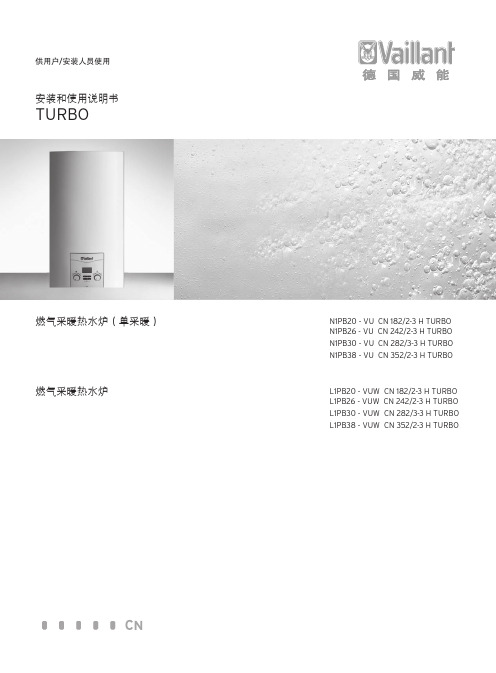
CN供用户/安装人员使用安装和使用说明书TURBO燃气采暖热水炉(单采暖)N1PB20 - VU CN 182/2-3 H TURBO N1PB26 - VU CN 242/2-3 H TURBO N1PB30 - VU CN 282/3-3 H TURBON1PB38 - VU CN 352/2-3 H TURBO燃气采暖热水炉L1PB20 - VUW CN 182/2-3 H TURBO L1PB26 - VUW CN 242/2-3 H TURBO L1PB30 - VUW CN 282/3-3 H TURBOL1PB38 - VUW CN 352/2-3 H TURBO供用户使用使用说明书TURBO目录设备特性 (1)设备简介 (1)1 文档说明 (2)1.1 其它适用资料 (2)1.2 保管 (2)1.3 符号说明 (2)2 安全 (3)2.1 紧急措施 (3)2.2 误使用风险警示 (3)2.3 设备检查和保修服务 (4)3 安装和保养说明 (4)3.1 安装和维护说明 (4)3.2 符合规定的使用 (4)3.3 安装地点的要求 (4)3.4 保养 (4)3.5 循环使用和废弃处理 (4)4 控制面板 (5)4.1 控制面板说明 ....................................................................54.2 运行准备.. (5)4.3 投入运行 (6)4.4 设置生活热水温度 (6)4.5 供暖模式 (7)4.5.1 设置供暖供水温度(未连接外部控制器) (7)4.5.2 设置供暖供水温度 (连接外部控制器) (7)4.5.3 关闭供暖(夏季模式) (7)4.5.4 设置室内温控器或气候补偿器 (8)4.6 状态显示(供工程师在维护和修理时参考) (8)4.7 故障检修 (9)4.7.1 缺水引起的故障 (9)4.7.2 点火故障 (9)4.7.3 排烟系统故障 (10)4.7.4 给燃气采暖热水炉/供暖系统注水 (10)4.8 关闭燃气采暖热水炉 (10)4.9 防冻 (11)4.9.1 防冻保护功能 (11)4.9.2 通过排水防冻 (11)4.10 维护与客户服务 (11)燃气采暖热水炉(单采暖)N1PB20 - VU CN 182/2-3 H TURBON1PB26 - VU CN 242/2-3 H TURBON1PB30 - VU CN 282/3-3 H TURBON1PB38 - VU CN 352/2-3 H TURBO燃气采暖热水炉L1PB20 - VUW CN 182/2-3 H TURBOL1PB26 - VUW CN 242/2-3 H TURBOL1PB30 - VUW CN 282/3-3 H TURBOL1PB38 - VUW CN 352/2-3 H TURBO设备特性图例1、 排烟口2、 空气入口3、 风机4、 风压开关5、 主热交换器6、 火焰检测电极7、 燃烧器8、 回水NTC9、 三通换向阀10、供水NTC 11、泄水阀12、燃气阀13、循环水泵14、板式热交换器15、自动排气阀16、火焰检测电极17、膨胀水箱18、膨胀水箱补气图 TURBO VUW 型主要零部件图示及名称设备特性感谢您选择使用威能集团的燃气采暖热水炉产品。
万和燃气灶使用说明书

MANUAL DE INSTRUCCIONES | HORNOSINSTALACIÓN, USO Y MANTENIMIENTOINSTALACIÓNARTEFACTO APROBADO PARA USO DIMICILIARIO.arImportante:(!) Previo a la instalación, asegurarse de que las condiciones de naturaleza y presión del gas son compatibles con los ajustes del artefacto.(!) La instalación y conexión debe realizarse de acuerdo con las normas de instalación vigentes, poniendo atención a las disposiciones aplicables en cuanto a la ventilación.(!) El mobiliario donde se coloque el horno debe ser de fácil acceso ante un eventual trabajo del Servicio Técnico Oficial sobre el artefacto.Todos los trabajos de instalación deberán llevarse a cabo por un profesional matriculado, y en un todo de acuerdo con lo establecido en las disposiciones y normas vigentes.Para cualquier operación de instalación, mantenimiento o limpieza del artefacto, se debe interrumpir la conexión con la red eléctrica, desconectando la ficha del tomacorriente, o cortando el suministro eléctrico desde el tablero de alimentación.(!) Es importante garantizar una correcta aislación térmica para evitar el calentamiento excesivo de las paredes, sobre todo si el material del nicho es de madera, o aglomerado. En tal caso, se recomienda utilizar cartón aislante.Procedimiento:Recomendaciones previas:• Verifique que el alojamiento previsto cumpla con las medidas requeridas y posea la ventilación definida (Figura 2).• Prevea la ubicación del tomacorriente con conexión a tierra. Debe estar conectado fuera del nicho y preferentemente del lado izquierdo del observador (Figura 4), de manera que se pueda desconectar fácilmente en caso de una remoción o reparación.• El cable de alimentación eléctrica se debe ubicar de modo tal que no alcance en ningún punto una temperatura que supere en 50ºC la temperatura ambiente.• El cable de alimentación no debe ser sustituido ni reparado por el cliente. Para ello debe recurrirse a un electricista matriculado.•La conexión a la red de gas deberá realizarse por medio de un tubo metálico rígido o bien por medio de untubo flexible de acero inoxidable de pared continua, el cual deberá estar certificado por un organismo reconocido por ENARGAS . El tubo de entrada del gas en cocinas y anafes se presenta con una rosca ½” gas macho.• Antes de conectar el artefacto, es aconsejable soplar las cañerías para desalojar posibles cuerpos extraños.•El adhesivo que une el aislante al mueble debe resistir temperaturas no inferiores a 90 ºC, para evitar deformaciones o desencoladuras del revestimiento.• Los muebles adyacentes a los nichos deben poder soportar una temperatura de 65º C por sobre la temperatura del ambiente (IRAM 2092-2-6).1- Instale un caño flexible de cobre o acero inoxidable con rosca G 1/2" (aprobado por ENARGAS ) a la cupla prevista para la conexión de gas de red, previamente colocando fijador al terminal macho del caño y procediendo luego a enroscar el mismo a la cupla.2- Presente el horno en el nicho sin arrimar del todo, para poder conectar el extremo restante de caño al barral, ajustando la tuerca junto a la arandela de sello provista con el caño.3- Verifique en todas las conexiones que no haya perdida de gas, mediante una solución jabonosa, nunca con el uso de llamas.4- Para la ventilación, conectar un caño galvanizado de 3" (75 mm) con salida al exterior, como se indica en la Figura 3.5- Arrime el horno a su posición final y verifique el artefacto cuente con la suficiente ventilación, tal como se indica en la Figura 2, ya que esta es esencial para la circulación de aire fresco en torno al artefacto. Por último, conecte la ficha eléctrica al tomacorriente y verifique el correcto funcionamiento del equipo.Cambio de tipo de gas: gas natural a gas licuado.El artefacto viene preparado de fábrica para su utilización con gas natural . Parautilizarlo con gas licuado , es necesario reemplazar el inyector del quemador del horno,regular el aire primario del quemador y mínimo en la válvula. Antes de efectuar esteprocedimiento, desconecte el cable de alimentación eléctrica.Procedimiento:• En la parte posterior de la cocina, quitar los tornillos del portapicos y retirarlo parar realizar el cambio de inyector.• Desenroscar el inyector y sustituirlo por el que corresponde al nuevo tipo de gas, según la tabla 1.Regulación del mínimo de la válvula1- Encender el quemador del horno girando la perilla hasta la posición de mínimo.2- Retirar la perilla y con un destornillador de punta plana, actuar en sentido horario sobre el tornillo de regulación ubicado en la parte externa de la varilla de la válvula hasta obtener una llama lo más corta y estable posible.3- Colocar nuevamente la perilla.Horno empotrable 900Horno empotrable 550Horno empotrable 900Horno empotrado 550Figura 1: tamaño del artefactoFigura 2: tamaño del nichoV I S T A F R O N T A LV I S T A S U P E R I O RMedidas expresadas en milímetrosFigura 3:Figura 4Distancia máx.al tomacorriente:Ø 1,30 mm Gas Natural Ø 1,50 mm Horno 550Horno 900Tabla 1: inyectores Gas Licuado Ø 1,0 mm Ø 1,1 mm Gas Natural Horno 550Horno 900Tabla 2: consumos Gas Licuado 2468 Kcal/h 2,870 Kw 3285 Kcal/h 3,820 Kw 2822 Kcal/h 3,282 Kw 3415 Kcal/h 3,972 Kw AG iMANTENIMIENTOPRECAUCIONES Y RECOMENDACIONES PREVIAS(!) La utilización prolongada del artefacto puede necesitar una ventilación complementaria, ya sea abriendo una ventana o por ventilación mecánica.(!) No está previsto que el artefacto sea utilizado por personas (incluídos niños) con capacidades físicas, sensoriales o mentales reducidas, o con falta de experiencia y conocimiento, excepto que se le haya dado instrucción o supervisión referida al uso del aparato por una persona responsable de su seguridad.Encendido: para encender el horno mediante el encendido electrónico, oprima y gire la perilla de la válvula en sentido anti-horario hasta la posición de máximo . Presione el interruptor de encendido y luego pulse la perilla firmemente para accionar el dispositivo de seguridad y el quemador se encenderá automáticamente. Mantenga la perilla presionada durante 10 a 15 segundos. Al soltarla compruebe si el quemador permanece encendido.Para encender el horno en forma manual , oprima y gire la perilla de la válvula en sentido anti-horario hasta la posición de máximo . Pulse esta perilla firmemente para accionar eldispositivo de seguridad. Encienda un fósforo y acérquelo al orificio ubicado en el piso del horno. Al tomar llama el quemador, mantenga la perilla presionada durante 10 a 15 segundos. Al soltarla compruebe si el quemador permanece encendido.• Para su seguridad, el horno Luxor Gas presenta en sus llaves un dispositivo que requiere que las perillas deban ser oprimidas para sacarlas de la posición de cerrado, evitando que por descuidos y travesuras infantiles se produzcan aperturas involuntarias.• Durante la operación de encendido del quemador, este dispositivo no deberá accionarse por más de 15 segundos. Si durante este tiempo el quemador no se enciende, dejar de actuar sobre el dispositivo, abrir la puerta del horno y esperar al menos 1 minuto antes de reencender.• En caso de una extinción accidental de las llamas del quemador, cerrar el mando del mismo y no intentar reencender éste durante por lo menos 5 minutos.• En caso de no permanecer encendido el quemador, cierre el pasaje de gas al horno girando la perilla mencionada a la posición cerrado y repita la operación. • Las superficies del horno se encuentran calientes durante el uso normal. Mantenga alejados de ellas a los niños.Encendido de luz: colocando el interruptor correspondiente a esta función en posición ON , encenderá la luz del o del horno.Los hornos Luxor Gas son aptos para cocinar hasta 5 niveles distintos. Para lograr un buen rendimiento, se recomienda precalentar el horno durante 10 minutos, antes de la cocción. Centrando los alimentos sobre la superficie de cocción y con una separación mínima entre los mismos de 4 cm., se obtiene resultados óptimos.La puerta de cristal brinda un cierre hermético a través de un burlete siliconado, y por su encastre en los laterales del horno, evita las fugas de calor hacia los costados.Encendido de la luz del horno.Las cocinas Luxor Gas vienen equipadas con luz en el horno. Para encenderla, colocar el interruptor correspondiente en posición ON .Uso del horno convector.Algunos modelos de cocinas Luxor Gas (ver Fig. 8) incorporan en sus hornos el sistema de convección que permite modificar el flujo de calor proveniente delquemador del horno para lograr una cocción uniforme de varios alimentos deforma simultánea y en menor tiempo. Es un componente ideal para la cocción de carnes o galletas.! A l utilizar el sistema convector se trabaja un 20% más rápido que en hornos convencionales, por este motivo la temperatura puede disminuir-se 20º o 25ºC a la indicada en las recetas y reducir a un tercio el tiempo de cocción recomendado.! Al introducir diversas bandejas en el horno, asegurarse de que ladistancia entre las mismas sea de 2,5 cm., de igual manera respecto a lasparedes del artefacto, para facilitar una circulación apropiada del aire.! Utilizar ba n dejas con bordes bajos o sin bordes sin emplear papel aluminio o tapas para no bloquear el flujo del aire, permitiendo que pueda llegar correctamente a los alimentos.Procedimiento:1- Distribuya los alimentos teniendo presente las precauciones indicadas en el manual.2- Precalentar el horno 20 minutos antes de la cocción. Distribuir los alimentos en el interior y colocar el interruptor del sistema convector en posición ON (ver Fig. 9). 3- Finalizado el proceso de cocción, cerrar la válvula del quemador del horno y posicionar el interruptor correspondiente en modo OFF.Limpieza del artefacto(!) Antes de realizar cualquier tarea sobre el artefacto, desconéctelo de la red eléctrica.Al momento de la limpieza, es conveniente seguir los consejos detallados a continuación:• El artefacto debe estar tibio o frío.• Para limpieza exterior o interior del horno, no utilice material abrasivo, líquidos cáusticos (lavandina, limpia hornos, etc.), esponjas metálicas ni limpiadores a vapor.• Use un trapo humedecido y jabón o detergente.• Enjuague las distintas piezas con agua limpia y séquelas.Limpieza del visor del hornoEs aconsejable limpiar el cristal interno de la puerta del horno con agua tibia y detergente, enjuagando con un paño húmedo, después de cada cocción. Cuando se desee realizar una limpieza más profunda, puede retirar fácilmente el cristal interno y aún la puerta completa, para realizar dicha tarea en un lugar más cómodo. El cristal interno se retira quitando los dos tornillos que sujetan las trabas.(!) Evite el uso de agua en exceso, ya que puede dañar las placas de aislación internas en la puerta del horno.Quitar la puerta del horno.1- Abra la puerta del horno completamente.2- Suba los enganches "A" hasta que calcen en las ranuras del brazo "B".3- Cierre levemente la puerta, aproximadamente unos 30º , retírela hacia afuera y levemente hacia arriba, de ese modo la bisagra se desprenderá y la puerta quedará libre.Rearmado.1- Verifique que los enganches "A" se encuentren en las ranuras del brazo superior "B".2- Introduzca los extremos del brazo superior "B" en las ranuras del frente de horno.3- Baje levemente la puerta hasta insertar los extremos de la pieza "C" en las ranuras interiores del frente de horno. Verifique que la traba calce en su alojamiento.4- Abra totalmente la puerta y destrabe los enganches "A". La puerta debe abrir y cerrar libremente.• Es de importancia que conserve este manual para poder consultarlo en todo momento. En caso de venta, cesión o de mudanza, este documento debe permanecer junto al artefacto para informar al nuevo propietario sobre su funcionamiento y sobre las advertencias correspondientes.• Antes de emplear el horno para cocción por primera vez, precalentarlo al máximo en lapsos de 30 minutos (con una adecuada ventilación del lugar) hasta eliminar los olores del artefacto. • Controle periódicamente la cañería de ventilación de sus artefactos. Los gases de combustión que no salen al exterior son peligrosos para la salud.• No intente localizar pérdidas de gas mediante el uso de llamas de ningún tipo. Sólo hágalo con agua jabonosa. Las burbujas indicarán el escape.• Antes de encender cualquier quemador o artefacto, es conveniente comprobar por la posición de las llaves o por el olfato si se ha producido alguna perdida de gas. Si ha ocurrido, cierre la llave respectiva, suprima toda llama, no encienda ni apague artefactos eléctricos y ventile el ambiente.(!)Si es necesaria alguna reparación en el artefacto, deberá ser realizada exclusivamente por el servicio técnico perteneciente a Luxor Gas. De ninguna manera intervenga o manipule por cuenta propia el artefacto u otras partes de la instalación.Estimado cliente:Parasolicitarinformacióntécnica,adquirirrepuestososolicitarServicioTécnico,puedecontactarseporlasiguientevía:E-mail:****************************.arFigura 8: hornos convectoresFigura 9: interruptor del sistema convector Horno convectorHorno convectorCOCINA 500。
万和壁挂炉说明书

这可能是有空气存留在水管或散热器中造成的。你能够用打开散热顶端的跑风口,把里面的空气放掉。以后,你必需调剂采暖炉的水压并确保压力稳固。这能够通过在采暖炉下面的放水口旋钮完成。2九、在洗澡的时候,我必需等上很长一段时刻才能取得热水!不管你的采暖炉处于何种工作状态或你的储水箱容积有多大,出热水的时刻是由存留在水管里的冷水量决定的。若是你的浴室离你的储水箱(或采暖炉)10米远,等待出热水的几秒钟感觉会比较长。30、自从安装了室内温控器,散热器整个下午都是凉的!这正是利用温控器的益处。下午阳光专门好的时候温控器会让采暖炉停止工作,充沛的光照会让你的房间维持舒适的温度。3一、有时候,当我将热水的水龙头开到最大时,水温仿佛变低了,是如此的吗? 是的。关于瞬时二次板换式采暖炉来讲,生活热水的温度取决于水的流速。水流越快,二次板换器对水的加热功能越差。当碰到这种情形时,你只要减小水的流量就能够够提升水温了。篇二:塞维达壁挂炉利用说明书篇三:壁挂炉利用注意事项及安装流程壁挂炉利用注意事项及安装流程
万和燃气热水器16n40说明书
万和燃气热水器16n40说明书一、燃气热水器使用说明1、首先当使用燃气热水器时,我们需要插入220V的电源。
2、接着然后打开连接到热水器的燃气管线开关。
3、按下燃气热水器面板上的电源开关。
此时,数字显示屏将显示温度和活力。
同时,通过不向上或向下的箭头调整火力大小,以控制水温。
4、朝热水方向打开钥匙(红色和蓝色标致在钥匙下方,红色方向表示热水,蓝色方向表示冷水),燃气加热器将自动打开。
同时水温可以通过水龙头的旋转方向进行调节。
将水龙头手柄拉向红色标致的末端,水温高,否则最冷。
二、使用燃气热水器的注意事项1、使用燃气热水器时,必须严格按照燃气热水器的说明进行正确操作,检查热水器在使用过程中是否正常燃烧,并在打开电源后先使用热水器然后气体排出。
2、使用燃气热水器时,请务必打开门窗或排风扇,因为燃烧燃气热水器需要一定量的空气。
如果不能保证足够的空气,则容易发生缺氧或一氧化碳中毒的危险。
因此,最好不要长时间使用燃气热水器,因为如果洗澡的人很多,则必须有一定的空间。
3、定期检查燃气热水器的喷嘴,点火针和感应针。
由于燃气加热器使用时间长,喷嘴,点火针和感应针容易积碳,会影响柔和的点火。
因此,在使用过程中应及时检查并清洁喷嘴和传感器针。
4、必须定期更换控制系统中的易损件。
如果发现控制系统出现故障或响应速度降低,则会对控制系统进行定期检查并及时进行维修。
使用燃气热水器后,必须将积水清洗干净。
对于两侧都有可移动面板的热水器,必须进行脱钙和接头更换。
5、燃气热水器在使用过程中检测到异味或火焰,表示燃气泄漏后,热水器和燃气管道必须立即停止工作。
关闭燃气阀并打开门窗,以免发生危险。
禁止在室内明火和开关,断开电器连接,并联系专业维修人员及时进行维护。
6、在冬季为避免因结冰而损坏热水器,每次使用后必须按照说明手册的操作说明将机器中的废水排干。
燃气热水器的使用寿命通常为6至8年。
超过使用寿命的热水器容易发生事故。
正确的方法是在使用寿命后更换机器。
热水炉说明书资料
全自动热水锅炉控制系统书说明用使年2012 浙江特富锅炉有限公司.公司简介特富锅炉——国家A级锅炉和压力容器定点制造单位,公司以先进的科技管理理念、精湛的工艺装备、高素质的员工队伍为基础,经过二十余年的发展创业,已成为当今锅炉行业首屈一指的现代化高科技企业。
公司拥有专门的科技研发机构“香港海基特科技热能有限公司”,为特富锅炉在全球能源领域提供核心技术支持,专业研发各类工业锅炉、余热利用锅炉、生物质锅炉等。
绿色工场“浙江特富热能科技有限公司”成立,专业研发制造智能型、节能环保锅炉。
特富锅炉是日本HAMADA公司国内制造合作伙伴,沸腾式燃烧锅炉远销东南亚、日本等国;德国布德鲁斯锅炉公司OEM定牌制造单位,产品制造遵循德国DIN、TRD标准。
特富,将引领行业能源利用的“绿色”发展期。
2目录第1章概述 (4)第2章使用前确认 (5)第3章电气安装及配线 (6)第4章电气操作说明 (7)第5章人机界面操作说明 (9)第6章锅炉操作说明 (19)第7章电气原理图及附录 (21)3第1章概述该自动控制系统采用工业全自动热水锅炉控制技术方案。
硬件按功能模块化设计,信号输入、输出、控制器件,全部采用知名品牌器件;软件面向对象设计,内嵌入精心设计的软件,软硬结合,对热水锅炉全自动安全运行进行自动控制和工况检测。
丰富的故障检测、故障报警、故障处理功能,保证了系统的安全可靠运行。
系统采用文本触摸屏,高量度、全中文显示,采用锅炉控制专用模块作为信息处理和中央控制单元。
以人机对话方式与锅炉用户交换信息,给操作者带来极大方便。
1)自动功能:即控制器能根据系统当前采集到的现场信号按用户设置的模式自动对系统进行控制。
2)软手动:即用户通过触摸屏上的功能键来实现对相应设备的开启或关闭操作。
3)故障识别:系统具备丰富的故障检测.故障报警等功能,最大限度地保证了锅炉的安全运行。
4第2章使用前确认2.1 现场货物确认打开包装后,确认以下项目:(1)请确认装箱清单里含有的控制箱、配件和说明书(2)请确认控制箱和配件是否完好;(3)确认订购的产品是否和所订货物相符;2.2 使用环境条件环境温度:-20℃~ +60℃相对湿度:5% ~ 95%2.3 工作条件接地要求:≤4Ω供电电源:AC380V +10%;50HZ5第3章电气安装及配线3.1 安装(1)柜体和一次仪表配件安装时应遵守设计院提供的施工图规定;(2)当图纸无明确标注时,柜体的安装遵守下述规定:①当柜后或侧面有进处线时,距墙不得小于800mm;②靠墙安装的低压柜,距墙距离不得小于25mm;(3)一次仪表安装时,因一次仪表涉及到锅炉正常运行的控制,当设计院图纸无明确标注时,应和锅炉厂家确认后,根据厂家提供的资料进行施工;3.2 配线(1)所有动力线缆安装时应遵守设计院提供的施工图规定(2)动力电缆和信号电缆分开走线,防止电磁干扰;建议传感器信号线缆采用屏蔽线;6第4章电气操作说明4.1 操作举例说明)4.1.1 操作面板(当系统出现异常,通过开关无法操作时,按下此开关,能切断控制电源输入。
- 1、下载文档前请自行甄别文档内容的完整性,平台不提供额外的编辑、内容补充、找答案等附加服务。
- 2、"仅部分预览"的文档,不可在线预览部分如存在完整性等问题,可反馈申请退款(可完整预览的文档不适用该条件!)。
- 3、如文档侵犯您的权益,请联系客服反馈,我们会尽快为您处理(人工客服工作时间:9:00-18:30)。
万和燃气采暖热水炉L1GB20说明书万和燃气采暖热水炉L1GB20使用说明
1、首先通上电和天然气,把地暖的两个阀门打开逆时针旋转。
2、通上自来水,打开壁挂炉下面的黑色补水钮逆时针旋转,将壁挂炉上压力表压力补到1.51到2之间都可以,关闭补水钮。
3、壁挂炉操作面板上ON/OFF为壁挂炉开关键,按一下打开。
4、雪花和太阳的键是模式选择键,冬天选择雪花是冬季模式,夏天选太阳模式,只有生活热水。
5、带暖气符号的加减按钮是调暖气温度,一般地暖调到50度,带水龙头符号的按钮是调生活热水温度的,调到40多度。