正确计算死区时间_英飞凌
三相SVPWM逆变器死区时间的硬件保护
三相SVPWM逆变器死区时间的硬件保护郭天娇;付成伟;高明;刘洋【摘要】A hardware protection circuit based on the research of inverter principle and dead-time mechanism is presented on the basis of existing inverter protection measures. If detects and controls the PWM input drive signal of the inverter by using the RC transient circuits and logic gate circuits. This circuit can ensure the safety of the inverter and the load by preventing the input singal to add to the inverter when the dead-time is too long or too short. Multisim simulation and experimental results demonstrate the effectiveness, and feasibility of the described protection measures.%基于逆变器工作原理和死区产生机理的研究,在现有逆变系统保护措施的基础上,提出了一种硬件保护电路.利用RC暂态电路和逻辑门电路等器件,对逆变器输入端的PWM驱动信号进行检测控制.当输入信号的死区时间过短或过长时,该电路能防止其加载到逆变器上,保证了逆变器和负载的安全.Multisim仿真和实验结果验证了所速保护措施的有效性和可行性.【期刊名称】《现代电子技术》【年(卷),期】2012(035)020【总页数】4页(P189-191,194)【关键词】逆变器;死区时间;硬件保护;SVPWM【作者】郭天娇;付成伟;高明;刘洋【作者单位】吉林大学物理学院,吉林长春 130012;吉林大学物理学院,吉林长春130012;吉林大学物理学院,吉林长春 130012;吉林大学物理学院,吉林长春130012【正文语种】中文【中图分类】TN911-34;TM464逆变电路在电力电子设备中占据非常重要的位置,作为将直流电转化为交流电的装置,在电机调速变频、高频开关电源、有源滤波等方面有着广泛的应用。
CCU6 输入捕获/输出比较单元6

CCPOS0 CC60R
CC60SR
2009-1-21
E1 Training
Copyright © Infineon Technologies 2008. All rights reserved.
Page 17
输入捕获/输出比较单元6(CCU6) 死区时间产生
死区时间功能的使用,避免了在互补输出时,避免上下管被同时导通,防 止外加功率器件的损坏。
比较 1
1
死区时间 控制
1
多通道控 制
trap 控制
3+3 2 2 2
3
1
捕获/比较 输入/输出 选择
端口控制
2009-1-21
E1 Training
Copyright © Infineon Technologies 2008. All rights reserved.
Page 7
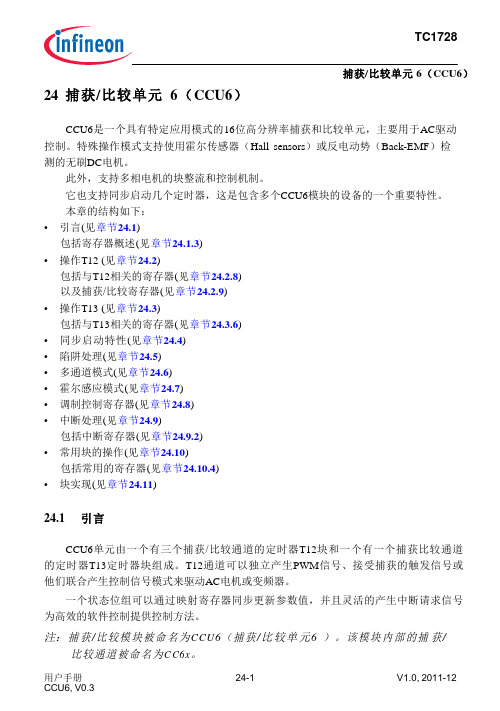
输入捕获/输出比较单元6(CCU6) 用于电机控制的结构图
由于版本更新等原因,可能会出现各版本间的资料说法有略微差异,请以 英飞凌网站公布的最新英文版本的产品数据手册(Data Sheet)和用户手 册(User Manual)为准!
2009-1-21
E1 Training
Copyright © Infineon Technologies 2008. All rights reserved.
2009-1-21
E1 Training
Copyright © Infineon Technologies 2008. All rights reserved.
Page 6
输入捕获/输出比较单元6(CCU6) 结构方框图
地址译码器 时钟输入 中断控制
英飞凌风机控制方案介绍

换相噪声
电机类型差异(反电势) ¬ 方波(梯形波) ¬ 正弦波 (永磁同步电机)
“正弦波电机+梯形波控制”
正弦波控制
2011/5/27 Copyright © Infineon Technologies 2009. All rights reserved. Page 5
直流无刷电机控制
正弦波控制的特点
Page 2
Table of contents
英飞凌风机方案概述 BLDC简易正弦波风机方案介绍 BLDC无传感器FOC方案介绍
5/27/2011
Copyright © Infineon Technologies 2009. All rights reserved.
Page 3
直流无刷电机控制
英飞凌风机控制方案介绍
英飞凌科技(中国)有限公司 工业和多元化市场
2011 马达控制及应用技术研讨会
Table of contents
英飞凌风机方案概述 BLDC简易正弦波风机方案介绍 BLDC无传感器FOC方案介绍
5/27/2011
Copyright © Infineon Technologies 2009. All rights reserved.
Page 9
英飞凌解决方案–基于FOC的永磁同步风机驱动方案
S1
R1
S3
S5
控制方式
PMSM
无位置传感器 FOC 空间矢量脉宽调制(SVPWM) 双直流母线电阻取样 XC878/XC836 10KHz 300-1200RPM <100W
调制方式 电流采样方式 MCU
AC ~
Udc
IKD04N60R
英飞凌tricore用户手册 第24章 捕捉比较单元CCU6
定时器13周期 54H 寄存器
U, SV U, SV 0000 0000H 类3 U, SV U, SV 0000 0000H 类3 U, SV U, SV 0000 0000H 类3
U, SV U, SV 0000 0000H 类3 U, SV U, SV 0000 0000H 类3
24-41 24-44 24-45
移量 读写
CC62SR
捕获/比较映射 48H 寄存器通道
U, SV U, SV 0000 0000H
CC62
复位 类3
页码 24-38
捕获/比较控制寄存器
CMPSTAT 比较状态
60H
寄存器
CMPMODIF 比较状态调 64H 制寄存器
U, SV U, SV 0000 0000H 类3 U, SV U, SV 0000 0000H 类3
T12DTC CC60R
定时器T12 28H 的死区时间 控
捕获/比较寄存 30H 器通道CC60
U, SV U, SV 0000 0000H 类3 U, SV U, SV 0000 0000H 类3 U, SV U, SV 0000 0000H 类3 U, SV U,SV 0000 0000H 类3
输入检测 寄存器
98H U, SV U, SV 0000 0000H 类3
丢失标识符寄 9CH U, SV U, SV 0000 0000H 类3
存器 服务请求 控制寄存
FCH - U, SV U, SV 0000 0000H 类3 x * 4H
器
24-127
24-128 24-130 24-133 24-112
用户手册 CCU6, V0.3
英飞凌风机调试工具使用指南

组成部分
磁场定向控制底层算法的Hex文件 上位机调试界面
Set date Copyright © Infineon Technologies 2011. All rights reserved. Page 3
风机调试工具概述
配套硬件
XMC1K 低压风机套件(推荐)
用户自己硬件
PI参数修改
Set date
Copyright © Infineon Technologies 2011. All right数设置界面
参数设置界面
SPI监测变量:提供两路DA输出,用户根据需求选择
¬ V1 ¬ V2 ¬ 控制按键
Page 7
风机调试工具安装
点击“下一步”
Set date
Copyright © Infineon Technologies 2011. All rights reserved.
Page 8
风机调试工具安装
耐心等待安装
Set date
Copyright © Infineon Technologies 2011. All rights reserved.
¬ 为与本软件配套,设计时,在单片机管脚定义和功能以及电流采样等部分务必 与低压开发套件一致,否则,软件不能自动调整。
¬ 设计参考: /download/index.php?act=list&id=649
Set date Copyright © Infineon Technologies 2011. All rights reserved. Page 4
风机调试工具使用说明——参数设置界面
参数设置界面
电路参数:根据用户实际设计选择,默认值为低压套件对应值。
英飞凌-IGBT模块在焊机应用中的选型

输出功率 结温(Tj)
芯片-外壳温 差∆Tjc
外壳-散热 器热阻 Rthch
散热器(-环境) 热阻Rthha
基板
散热器
壳温(Tc)
外壳-散热器温差∆Tch
散热器温度(Th)
散热器-环境温差 ∆Tha
10.02.2010
Copyright © Infineon Technologies 2010. All rights reserved.
Q1
Q3
Q1 t
Q4
Q2
I1
I2
ip
Q4 t
vAB
Vin
0
t
Vin
损耗特点:
vrect 0
Vin/K
t0 t1 t2 t3 t4 t5
t6 t7 t8 t9 t10 t11
IGBT:导通时间长,导通损耗大,开关损耗小;
FWD:续流时间长,导通损耗大;
最佳IGBT芯片:T4芯片
t
t12 t13
10.02.2010
环境温度 (Ta)
Page 17
IGBT模块热计算
IGBT模块各个部分的温差∆T取决于 1)损耗(芯片技术、运行条件、驱动条件); 2)热阻(模块规格、尺寸) 模块芯片的结温是各部分的温差和环境温度之和: Tj = ∆Tjc + ∆Tch + ∆Tha + Ta 如果假设壳温Tc恒定,则Tj = ∆Tjc + Tc; 如果假设散热器温度Th恒定,则Tj = ∆Tjh + Th。 IGBT的平均结温取决于平均损耗、Rthjc和壳温Tc。 在实际运行时,IGBT的结温是波动的,其波动幅度取决于瞬态损耗和 Zthjc, 而Zthjc又和运行条件(如变频器输出频率)有关。 IGBT的峰值结温为平均结温+波动幅值。
英飞凌高效开关电源系统解决方案

PGND GATE VCC P-DSO-14 VSENSE OVP BOP VB_OK
VREF VBTHL_EN
90 ~ 270 Vac
Line Filter
RGD CE RCS1 RGS
CB
RBVS1
RBVS4
RBVS2
RBVS5
RBVS3 DBRO1 DBRO2 QRel RRel RBRO1 RBRO2 VB_OK CS GATE PGND VSENSE OVP
Page 11
英飞凌开关电源解决方案
PFC 部分 CoolMOS C6
Set date
Copyright © Infineon Technologies 2009. All rights reserved.
Page 12
英飞凌开关电源解决方案
PFC 部分 CoolMOS C6
引脚电感 dv/dt 触发震荡
高体二极管可靠性 低反向恢复电荷 (Qrr)
益处
便于控制的开关特性 与C3相比具有更高的轻载效率
CoolMOSTM 品质,高可靠性体二极管
突出的可靠性,品质保证 与之前的几代CoolMOSTM 产品相比,价格更优
Copyright © Infineon Technologies 2009. All r 96%
BOFO ISENSE SGND ICOMP P-DSO-14
PGND GATE VCC VSENSE OVP BOP VB_OK
BOP
RBRO1 RBRO2 RBRO3 CBRO
FREQ
20uA
DBYP RNTC C7
Blanking time L2H 30us H2L 1us
STM32高级定时器死区控制

STM32高级定时器都带有死区控制功能,一般来说死区控制主要用于马达、变频器等控制。
一、死区时间概念BLDC控制换相电路如下死区时间是两路互补PWM输出时,为了使桥式换相电路上管T1和下管T2、上管T3和下管T4、上管T5和下管T6不会因为开关速度问题发生同时导通(同时导通电源会短路)而设置的一个保护时段。
假设STM32高级定时器OCX和OCXN输出互补通道PWM,极性都是高电平有效,则下图中标注“延迟”那段时间就是死区时间,此时间段上管和下管都没有导通。
二、STM32高级定时器死区时间计算1. 配置寄存器2. 死区时间计算示例假设STM32F407的高级定时器TIM1的时钟为168MHz,设置tDTS=1/168us。
死区时间设置2us,经过估算该死区时间落在DTG[7:5]=110段。
(32+DTG[4:0]) /21 us= 2us,计算出DTG[4:0]=10=01010B,再与DTG[7:5]拼接,最后算得DTG[7:0]=10=11001010B=0xCA。
死区时间设置4us,经过估算该死区时间落在DTG[7:5]=111段。
2*(32+DTG[4:0]) /21 us= 4us,计算出DTG[4:0]=10=01010B,再与DTG[7:5]拼接,最后算得DTG[7:0]=10=11101010B=0xEA。
需注意死区时间计算是分段计算,每段公式不一样。
三、配置死区时间过程可能出现的问题问题:发现插入死区时间后,没有互补脉冲输出了。
一般是死区参数设置不合适导致出现了以下两种情况。
如果延迟时间大于有效输出(OCx 或OCxN)的宽度,则不会产生相应的脉冲。
注意:插入死区是为了保证桥式驱动电路中上下桥臂的开关管不会同时导通,提高控制安全性,但不是死区时间越长越好,死区是以牺牲开关管有效驱动脉冲时间为代价的,死区时间长短是由开关管硬件开关的速度决定。
- 1、下载文档前请自行甄别文档内容的完整性,平台不提供额外的编辑、内容补充、找答案等附加服务。
- 2、"仅部分预览"的文档,不可在线预览部分如存在完整性等问题,可反馈申请退款(可完整预览的文档不适用该条件!)。
- 3、如文档侵犯您的权益,请联系客服反馈,我们会尽快为您处理(人工客服工作时间:9:00-18:30)。
AN2007-04 H o w t o c a l c u l a t e a n d m i n i m i z e t h e d e a dt i m e r e q u i r e m e n t f o r I G B T s p r o p e r l yPower Management and DrivesEdition 2008-05-07Published byInfineon Technologies AG81726 München, Germany© Infineon Technologies AG 2008.All Rights Reserved.Attention please!THE INFORMATION GIVEN IN THIS APPLICATION NOTE IS GIVEN AS A HINT FOR THE IMPLEMENTATION OF THE INFINEON TECHNOLOGIES COMPONENT ONLY AND SHALL NOT BE REGARDED AS ANY DESCRIPTION OR WARRANTY OF A CERTAIN FUNCTIONALITY, CONDITION OR QUALITY OF THE INFINEON TECHNOLOGIES COMPONENT. THE RECIPIENT OF THIS APPLICATION NOTE MUST VERIFY ANY FUNCTION DESCRIBED HEREIN IN THE REAL APPLICATION. INFINEON TECHNOLOGIES HEREBY DISCLAIMS ANY AND ALL WARRANTIES AND LIABILITIES OF ANY KIND (INCLUDING WITHOUT LIMITATION WARRANTIES OF NON-INFRINGEMENT OF INTELLECTUAL PROPERTY RIGHTS OF ANY THIRD PARTY) WITH RESPECT TO ANY AND ALL INFORMATION GIVEN IN THIS APPLICATION NOTE.InformationFor further information on technology, delivery terms and conditions and prices please contact your nearest Infineon Technologies Office ().WarningsDue to technical requirements components may contain dangerous substances. For information on the types in question please contact your nearest Infineon Technologies Office.Infineon Technologies Components may only be used in life-support devices or systems with the express written approval of Infineon Technologies, if a failure of such components can reasonably be expected to cause the failure of that life-support device or system, or to affect the safety or effectiveness of that device or system. Life support devices or systems are intended to be implanted in the human body, or to supportand/or maintain and sustain and/or protect human life. If they fail, it is reasonable to assume that the healthAP99007Revision History: 2007-08 V1.0 Previous Version: nonePage Subjects (major changes since last revision)FirstreleaseAuthor: Zhang Xi IFAG AIM PMD ID AETable of Contents Page 1Introduction (5)1.1Reason of IGBT bridge shoot through (5)1.2Impact of dead time on inverter operation (5)2Calculate proper dead time (6)2.1Basics for calculating the dead time (6)2.2Definition of switching and delay times (7)2.3Influence of gate resistor / driver output impedance (8)2.4Impact of other parameters on delay time (9)2.4.1Turn on delay time (9)2.4.2Turn off delay time (10)2.4.3Verification of calculated dead time (12)3How to reduce dead time (13)4Conclusion (14)Bibliography (15)1 IntroductionIn modern industry the voltage source inverter with IGBT devices is used more and more. To ensure proper operation, the bridge shoot through always should be avoided. Bridge shoot through will generate unwanted additional losses or even cause thermal runaway. As a result failure of IGBT devices and whole inverter is possible.1.1 Reason of IGBT bridge shoot throughThe typical configuration of a phase-leg with IGBTs is shown in the following figure. In normal operation two IGBTs will be switched on and off one after the other. Having both devices conducting at the same time will result in a rise of current only limited by DC-link stray inductance.Figure 1 Typical configuration of a voltage source inverterOf course no one will turn on the two IGBTs at the same time on purpose, but since the IGBT is not an ideal switch, turn on time and turn off time are not strictly identical. In order to avoid bridge shoot through it is always recommended to add a so called “interlock delay time” or more popular “dead time” into the control scheme. With this additional time one IGBT will be always turned off first and the other will be turned on after dead time is expired, hence bridge shoot through caused by the unsymmetrical turn on and turn off time of the IGBT devices can be avoided.1.2 Impact of dead time on inverter operationGenerally there are two types of dead time, the first one is control dead time and the second is effective dead time. The control dead time is the dead time, which will be implemented into control algorithms in order to get proper effective dead time at the devices. Target for setting control dead time is to ensure that effective dead time is always positive. Due to the fact that calculation of control dead time is always based on a worst case consideration, an effective dead time being a significant portion of the control dead time will result. Providing dead time can on one side avoid bridge shoot through but on the other side it has also adverse effect. To clarify the effect of dead time, let’s consider one leg of the voltage source inverter as shown in Figure. 2. Assuming first that output current flows in direction shown on the illustration IGBT T1 switches from ON to OFF and IGBT T2 switches from OFF to ON after slight dead time. During effective dead time both devices are off and freewheeling diode D2 is conducting output current. So negative DC link voltage is applied to the output, which is desired here. Consider the other case that T1 switches from OFF to ON and T2 from ON to OFF, then, with current in the same direction D2 still conducts the current during dead time, so that output voltage will be also negative DC link voltage, which is undesired here. The conclusion can besummarized as follows: during effective dead time output voltage is determined by the direction of output current but not the control signal.If we consider output current in the opposite direction than illustrated in figure 2, then we will gain a voltage if T1 switches from ON to OFF and T2 switched from OFF to ON. So in general output voltage and as a result also output current will be distorted with application of a dead time. If we choose a dead time unnecessary large, then in case of an induction motor the system will become instable and may cause some destructive effects [1]. So the process of choosing dead time is very important and should be performed very carefully.CurrentFigure 2One leg of voltage source inverterThis application note will explain how to measure delay time of IGBTs in practice and how to calculate the control dead time properly based on measurements.2 Calculate proper dead timeAs already mentioned, dead time should be chosen on one hand to satisfy the need of avoiding bridge shoot through, on the other hand dead time should be chosen as small as possible to ensure correct operation of voltage source inverter. So a big challenge here is to find out a proper dead time for a dedicated IGBT device and driver.2.1 Basics for calculating the dead timeFor calculation of control dead time we use the following equation:()[]2.1)(______×−+−=MIN PDD MAX PDD MIN ON D MAX OFF D dead t t t t t (1)Where Td_off_max : the maximal turn off delay time. Td_on_min : the minimal turn on delay time.Tpdd_max : the maximal propagation delay of driver. Tpdd_min : the minimum propagation delay of driver.1.2: safety margin to be multiplied.In this equation the first term td_off_max-td_on_min is the difference of the maximal turn off delay time andthe minimal turn on delay time. This term describes characteristic of IGBT device itself plus gate resistor which is used. Since fall and rise time is normally very short in comparison with delay time, they will be not considered here. The other term tpdd_max-tpdd_min is the propagation delay time difference (delay timemismatch) which is determined from driver. This parameter will be found normally in datasheet of driver from driver manufacturers. Typically this value is quiet high with opto-coupler based drivers.Sometimes dead time will be calculated from typical datasheet values just multiplying by a safety factor from field experience. This method will work in some cases but is not precise enough in general. With measurements shown here, a more precise approach will be presented.Because IGBT datasheet only gives typical values for standardized operation condition, it is necessary to obtain the maximal values for dedicated driving condition. For this purpose a series of measurements is done in order to obtain proper value for delay time and then to calculate dead time.switching and delay timesof2.2 DefinitionSince we will talk a lot about switching and delay times, it is necessary to give a clear definition here. Infineon Technologies defines the switching time of IGBT as follows:t d_on: from 10% of Vge to 10% if I c.t r: from 10% of Ic to 90% of I c.t d_off : from 90% of Vge to 90% of I c.t f: from 90% of Ic to 10% of I c.Figure 3 Definition of switching times.2.3 Influence of gate resistor / driver output impedanceThe choice of gate resistor will have significant impact on switching delay time. Generally to say, the larger the resistor is the longer the delay time will be. It is recommended to measure delay time with dedicated gate resistor in application. A typical switching time vs. gate resistor value diagram is shown in the following figures:Figure 4Switching times vs. Rg @25°CAll tests were done with FP40R12KT3 module, gate voltage is -15V/+15V, DC link voltage is 600V and switched current is nominal current of 40A.2.4 Impact of other parameters on delay timeBesides the gate resistor values, there are other parameters having significant impact on delay times: • Collector current.•Gate drive supply voltage.2.4.1 Turn on delay timeTo estimate this relationship, a series of measurements was done. First the dependence of turn on delay time and current was investigated. The results are shown in the next figure:Figure 6 The turn on delay time vs. switched current IcAll tests were done with a FP40R12KT3 module at a DC link voltage of 600V, gate resistor is chosen according to datasheet value.From results above it can be seen that turn on delay time is almost constant with variation of collector current Ic. With -15V/+15V gate voltage turn on delay time will get larger than with 0V/+15V gate voltage [2]. For further calculation of control dead time this variation will be neglected since it is quiet small and provides even additional margin.2.4.2 Turn off delay timeThe most important factor in the calculation of dead time is the maximal turn off delay time. Since this value determines almost entirely how long the final calculated dead time will be. So we will investigate this delay time in detail.In order to obtain the maximum turn off delay time following considerations have to be done:1. What and how long is the turn on delay time caused by IGBT device itself?To answer this question the following test based on a characterization driver board is done in laboratory. The characterization driver board is considered as an optimal driver, which means that this particular driver will cause no delay (which is almost true with an oversized driver), so the whole delay time is considered to be caused by the IGBT device itself. Following block diagram shows test setup:Figure 7 Block diagram of test with ideal driver2. What is the maximal turn off delay time if the threshold voltage of IGBT has the minimal value in datasheets? (this reflects the tolerance of Vth from module to module)To answer this question an additional diode is connected to simulate the reduced Vth voltage. The diode has a voltage drop of approximately 0.7…0.8V, which is quite similar to the Vth variation of FP40R12KT3 module. Following block diagram shows principle test setup:Figure 8 Block diagram of the test to simulate variation of Vth in worst case.3. What is the impact of driver output stage on switching times?To answer this concrete question the drivers on the market were splitted into two categories, one with mosfet transistor output stage and the other one with bipolar transistor output stage. For each category separate measurements were made.To simulate drivers with mosfet output stage, another additional resistor was connected and has been considered as the on state resistor Rds(on) of Mosfet transistor. The diode for simulation of Vth variation remained. The following block diagram shows the principle test setup:Figure 9 Block diagram of test to simulate variation of Vth and driver with mosfet output.4. What is the impact of the driver with bipolar transistor output stage?To answer the question an additional diode which simulated the voltage drop on bipolar transistor within output stage was connected. The following block diagram shows principle test setup:Figure 10 Block diagram of the test to simulate the variation of Vth and driver with bipolar transistor outputWith the configurations shown above the measurement of turn off delay time was done in our laboratory with module FP40R12KT3 and driver board which had been considered as optimal. Test conditions were Vdc=600V, Rg=27Ω. Results are shown in the next two figures:Figure 11 Turn off delay time vs. Ic @25°CFigure 12 Turn off delay time vs. Ic @125°CFrom the results we can see that there is a significant increase of turn off delay time with decrease of the switched current Ic. So just simply calculate dead time according to a chosen gate resistor is obviously not precise enough. Measuring the delay time under the dedicated driving condition then calculating dead time according to these values is a better and more precise way. Normally measurement until 1% of the nominal current would be enough to give a sufficient overview for calculating required dead time.Another point to be considered here is that the turn off delay time will increase with 0V/+15V gate drive, and the impact of output stage on switching times will be bigger with 0V/+15V switching. This means that with 0V/+15V switching voltage special care has to be taken by choosing the driver. Additionally, the increase of td_off with lower switched collector current Ic should be considered also.As an example: the HCPL-3120 driver IC will be considered here. This driver IC has a Mosfet output stage for switching off. From diagrams above we can read the value for td_off under 0V/+15V switching condition is roughly 1500ns. The td_on in this case is about 100ns. The tpdd_max-tpdd_min of this driver IC according to datasheet is 700ns. Applying these values to the formula (1) results in a dead time of about 2.5µs.2.4.3 Verification of calculated dead timeWith the discussion above and the formula (1) given in chapter 2.1 it is now possible to calculate the required dead time based on the measurements above. With the calculated dead time, a worst case measurement can then be performed to verify if the chosen dead time is enough or not.From the measurement it can be seen that the turn off delay time increases with temperature. From this reason it is preferable that the test should be done both at cold and hot condition.The schematic illustration of the test looks like following:Figure 13 Schematic illustration of test to check calculated dead time valueThe bottom IGBT has to be switched on and off, then the same for the top one. The time between the two pulses should be adjusted to be the value of calculated dead time for the dedicated driving condition. The negative dc-link current can then be measured and if the dead time is sufficient, a shoot through current should not be observed.Since there is no current through both IGBT, the described test represents the worst case condition for dead time calculation. From the discussion of turn off delay time it is known that dead time will be longer with decrease of collector current, so in case there flows no current, turn off delay time should be largest, which leads to a need of largest dead time. If there is no shoot through current at zero collector current then the chosen dead time is for dedicated driving condition sufficient.3 How to reduce dead timeFor a proper calculation of control dead time the dedicated driving condition should be considered: •What is the applied gate voltage to the IGBT?•What is the chosen gate resistor value?•What type of output stage does the driver have?Based on these conditions a test should be made, from the test results the control dead time can then be calculated using equition (1).Since dead time has a negative impact on the performance of inverter, it has to be minimized. Several methods can be taken.•Take a driver strong enough to sink or source the peak IGBT gate current.•Use negative power supply to accelerate turn off.•Prefer drivers based on fast signal transmission technology like Coreless Transformer Technology to drivers based on traditional opto-coupler technology.•If 0V/15V gate drive is used then consider use of separate Rgon/Rgoff resistor as described below.From measurements shown in chapter 2.3 a very strong dependence of Td_off and gate resistor value can be observed. If the Rgoff reduced then the td_off will be reduced as well as dead time. Infineon suggests reducing the Rgoff to 1/3 of the Rgon value if 0V/15V gate voltage is used. One possible circuit for separate Rgon and Rgoff is as follows:Figure 14 Suggested circuit with 0V/15V gate voltage.R1 should be chosen to satisfy the following relation:)(31int int 11g gon g gongon R R R R R R R +⋅=++⋅(2)int int 1221g gon g gon gon R R R R R R +−⋅⋅==>(3)From equation (3) it is to be noticed that the requirement Rgon>2Rgint has to be fulfilled to get a positivevalue of R1. However, with some modules this requirement can not be true. In this case, R1 can be omitted completely.The diode should be a schottky type diode.Another very important issue with 0V/15V gate voltage is the parasitic turn on effect. This issue can be also solved if suggested circuit is used. For more details on parasitic turn on please refer to AN2006-01[2].4 ConclusionIn this application note an approach of measuring switching times of IGBT and then calculating the control dead time is introduced. First dependence of switching time on gate resistor value was shown, and then influence of gate driver and collector current on switching times was discussed. Finally possible methods to reduce dead time were introduced.Bibliography[1] D.Grahame Holmes, Thomas A. Lipo: …Pulse width modulation for power converters: principles andpractice“, IEEE Press, 2003. ISBN 0-471-20814-0[2] Driving IGBTs with unipolar gate voltage./dgdl/an-2006-01_Driving_IGBTs_with_unipolar_gate_voltage.pdf?folderId=db3a304412b407950112b408e8c9000 4&fileId=db3a304412b407950112b40ed1711291。