2-4-Configuring EIGRP Authentication
第5章 路由协议1

200.200.1.0/24 200.200.0.1
说明:
1、管理员配置RIP协议时,只需要考虑本路由器的网 络连接,与其它路由器的连接情况无关。
2、当路由器发布路由更新时,只有那些用network声 明过的网络会被发送给邻居路由器。
3、对于使用私有IP地址的网络,其地址不应该路由 到外网上,所以这种网络不应该使用network声明。
内部网关协议(IGP):RIP、IGRP、IS-IS、OSPF、 EIGRP等。
其中IGP根据其原理又分为距离向量路由协议(DV)、 链路状态路由协议(LS)和混合路由协议。
路由要点
路由表结构: R 66.0.0.0/8 [120/1] via 200.1.1.2, 00:00:10, Serial 0/0
配置举例
R1 S1:200.1.1.2/24 S0:200.1.1.1/24 R4 S1:30.1.1.2/24 R3 S0:30.1.1.1/24 S1:20.2.0.2/16 E0:190.1.1.1/16 PC 190.1.1.2/16 各S1端为DCE端。 S0:20.1.0.1/16 S1:20.1.0.2/16 R2 S0:20.2.0.1/16
链路状态路由协议
OSPF(最短路径优先协议)属于链路状态路由协议。 在这种协议下,路由器会通过探查,获取整个网络(自治 系统)的拓扑结构,并用Dijkstra算法生成一颗最小生成 树(SPF)。路由表就是根据最小生成树的路径生成的。 在OSPF中,每当网络发生变化(增加新路由器、网络故 障)时,就会发送链路状态通告(LSA),各路由器就根据 这些LSA构建拓扑信息数据库,再生成SPF和路由表。
RIP的配置
路由器默认是不启用任何路由协议的,所以对于需要配 置动态路由的路由器需要手工启用路由协议。
CCIE R&S K3 相关考点
CCIE R&S K3版本详细分析Section 1 - Layer 21.1 Troubleshoot Layer 2 Switching●Access-map●F0/10 facing BB have root guard(remove it)●No ip cef (not sure if that is a fault)1.2 Implement Access Switch Ports of Switched NetworkConfigure all of the appropriate non-trunking switch ports on SW1 – SW4 according to the following:●SW1 is the server for the VLAN Trunking Protocol version 2 domain "CCIE" (VTP password "cisco" )●SW2, SW3, SW4 are expecting SW1 update their VLAN database when needed●Configure the VLAN ID and Name according to the table below (case sensitive)----already in preconfiguration of SW1except vlan 42●Configure the access ports for each VLAN as per the diagram●Using a single command ensure that all access ports are transitioned to forwarding state as quickly as possible●Using a single command ensure that the interface is forced the err-disabled state if BPDU is received by any ports●Ensure that any BPDU received by the access ports facing the backbone devices (and only these devices) have no effectto your spanning tree decision●Don’t forget to configure the Layer 3 interfaces and to include SW1’s port fa 0/4 into VLAN 441.3 Spanning-Tree Domains for Switched NetworkConfigure the switches according to the following requirements:●Both switches must have a seperate instance per vlan●Ensure that SW1 is the Root Switch, and SW2 the Backup Switch for all odd vlans used throughout the exam●Ensure that SW2 is the Root Switch, and SW1 is the Backup Switch for all even vlans used throughout the exam●Configure instance per vlan and rapid transition for forwarding●Configure to 30 seconds that time that all switches wait before their spanning-tree processes attempts to re-converge if itdidn’t receive any spanning-tree configuration message1.4 Switch Trunking and Ether ChannelUse the following requirements to configure the Etherchannel of SW1, SW2, SW3 and SW4:●Use encapsulation 802.1q●Configure the Industry standard Etherchannel between SW1 and SW2.●Configure the Cisco proprietary Etherchannel between SW3 and SW4.●Ensure that SW1 and SW3 must initiate the negotiation and SW2 and SW4 must not start the negotiation1.5 Spanning-Tree Tuning●Find the vlan between R2 and SW4. The priority of that Vlan must be 12330 on SW2●Ensure that the port fa0/20 is in the forwarding state rather than the blocking state for even vlans on SW4.●You must do this without changing any configurations on SW4●Use the highest numerical value to complete.1.6 RSPAN●Any traffic received (only received)from VLAN_BB1 and VLAN_BB2 must be replicated to a traffic analyzer connected toSW4 Fa0/15 via VLAN 999●You need to monitor any interfaces connecting to VLAN_BB1 and VLAN_BB2●Any traffic flowing through the trunk between SW3 and SW4 must be replicated to another traffic analyzer connected toSW4 Fa0/16●There should not be any configuration regarding this on SW3.●Don’t create any new VLAN while configuring this1.7 PPP & CHAP●R4 must require R1 and R2 to authenticate using CHAP but R1 and R2 must not require R4 to authenticate●R1 and R2 cannot use ppp chap hostname, they can use ppp chap password with "CCIE".●Make sure that all CHAP passwords are shown in clear int the configuration—no service password-encryption is inpreconfiguration●Use radius server at YY.YY.44.200 as authentication server and fallback to the local AAA database in case the server isunreachable●Use CISCO as key required by the Radius server●Make sure AAA authentication does not affect any console or line VTY from any PPP devices (ensure that there is nousername prompt either)●Use only default method list for both console and line VTY.Section 2 – Layer 3 Technologies2.1 Configure OSPF Area 0, 142 and 51 as per diagram●OSPF process ID can be any number●Router ID must be stable and must be configed using the IP Address of Lo0●Lo0 interfaces must be advertised in the OSPF area as shown in the IGP topology diagram and must appear as /32routes●Ensure that all switches attached to the VLAN 123 exchange routing updates primarily with SW1 and then SW2 (in caseSW1 goes down) Use highest numerical values●Make sure that all 3 prefixes for the backbone links (150.BB.YY.0/24) appear as OSPF External Type 2 routes in routingtable●Do not create any additional OSPF areas. Do not use any IP address not listed in the diagram2.2 – Implement IPv4 EIGRPConfigure Enhanced Interior Gateway Routing Protocol (EIGRP) 100 on SW2 in order to establish EIGRP neighbor with Backbone 3 in the IGP topology diagram.●BB3 has IP address 150.3.YY.254 and is using AS number 100●Disable auto-summary2.3 – Implement RIP Version 2Configure RIP Version 2 (RIPv2) between R3 and BB1●RIP updates should be sent only out to the interface per the IGP topology●R3 must accept from BB1 only the following prefixes1.1.1199.172.4.0/241.1.2199.172.6.0/241.1.3199.172.12.0/241.1.4199.172.14.0/24●Use Standard ACL with a single entry●Disable Auto Summarization2.4 Redistribute RIP into OSPF●Redistribute RIP into OSPF on R3 such that the routing table on R5 contains the following.1N2 199.172.14.0/242N2 199.172.12.0/243N1 199.172.6.0/244N1 199.172.4.0/245N2 150.1.YY.0●Use Standard ACL with a single entry2.5 Redistribute EIGRP into OSPFRedistribute EIGRP into OSPF on SW2 such that:●Redistributed EIGRP routes must not be advertised into Area 51●Redistributed EIGRP routes must be advertised into Area 0 and 142 as OSPF Type E2●SW2 must advertise an inter-area default route into Area 51 only●Don’t use any route-map and do not add any static route anywhere2.6 Implement IPv4 BGPConfigure iBGP peering for R1, R2, SW2, R3 and R5 as per the following requirement:●Where possible failure of a physical interface should not permanently affect BGP peer connections●Minimize number of BGP peering sessions and all BGP speakers in AS YY except SW2 must have only one iBGP peer ●All BGP routes on all devices must be valid routes●Configure BGP as per diagram●BGP routes from BB1 must have community values 254 207 103 in AS YY●BGP routes from BB2 must have community values 254 208 104 in AS YY●Make sure that all BGP speakers in AS YY (even R2) are pointing all BGP prefixes from AS 254 via BB1 only (their BGPnext hop must be the IP address of the backbone devices)2.7 Implement Performance RoutingImplement PfR to achieve the following policies:●R4 must be the master controller●R1 and R2 must be the Border Routers●Ensure that PfR sessions are established using the Lo0 interface only●Configure tunnel to have direct connectivity between Border routers● A specific traffic (marked with DSCP "CS2") from VLAN_44 to VLAN_55 must be routed via R1●Another traffic (marked with DSCP "CS4") from VLAN_44 to VLAN_55 must be routed via R2●Use Extended ACL with a single entry●Use active probes only●If required by you solution you may use any prefix that is not used in your topology●Do not use max-range-utilization, resolve utilization and resolve range in OER policy●You should user access-list specifying only source address and DSCP value●You must use "set mode select-exit good"the question indeed ask to complete the task with below parameters●R1R2 float default route with administrative distance 250●R1R2: lowest value of load-interval(30) with interface facing SW1 and SW4●Learn:monitor-period=1;periodic-interval=0●Oer master: periodic 902.8 Implement Performance RoutingContinue as per following:●PfR must ensure that the voice traffic is routed via an exit which provides a maximum delay 40ms and a maximum jitter of5ms●Set the frequency of probes to 2 seconds●Make sure that all exits are constantly probed●The voice traffic is sourced from VLAN_$$ destined to the voice gateway R5 (YY.YY.55.5) and marked with DSCP "EF"●You should user access-list specifying only source address and DSCP value●You must use "set mode select-exit good"2.9 Implement IPv6The ipv6 address are preconfigured for you:●Configure OSPF Area 142 between R1, R2, R4●Configure IPv6 PIM sparse mode on the serial interfaces●R4's interface f0/0 should be the static RP-address (FEC1:CC1E:44::4) for the multicast group FFTS::4000:4000●R1 interface Gi 0/0 should be able to join the multicast group FFTS:4000::4000●Determine the value of TS. The multicast stream should be a transient one and the scope should be 5 for company wide.●You should be able to ping the multicast group from R2 Interface s0/0/0●IPV6 icmp error interval limit to 5 messages per second2.10 Implement Advanced IPv6 feature●In an attempt to reduce link-layer congestion, limit to 4 messages per second the rate at which all IPv6 enabled devicesgenerate all IPv6 ICMP error messages●Enable Netflow for IPv6 on R1 to monitor the traffic entering Area 142●Export the flows every 3 hours to the server YY.YY.44.100 (port 9876)●Use R1-Lo0 as source address for the exports●Aggregate the flows per destination and allow up to 20000 entries in the cache●Inactive entries must be deleted from the cache after 2 minutes of inactivitySection 3 – IP Multicast3.1 IPv4 Multicast●There is a multicast source on VLAN 44 and clients are located on the BB3 subnet (150.3.YY.0/24). Use a dynamicprotocol that supports PIM v1 and v2●Configure R1 and R2 loopback0 to be a rendezvous point (RP).●Ensure that R2 should be the preferred RP rather than R1.●Simulate clients have sent requests to join the multicast group 239.YY.YY.1.●Make sure R4 f0/0 is able to ping this multicast IP.3.2 PIM Tuning●Ensure PIM register message should reach RP via SW1.●If SW1 goes down, PIM register messages should reach RP via one of the switches in Area 0.●Vlan 33 should not receive any RP messagesSection 4 – Advanced Services4.1 Network Address Translations (NAT)You are required to implement NAT. You need to match the output in the screenshots provided.●Do not propagate and prefix from the network 100.0.0.0/8 in any routing protocol.●You are allowed to add one /24 static in too four devices.●Do not add any static route in R4.4.2 MLS QoSConfigure your four switches according to the following requirements:●Make sure that ports SW1-f0/1 to SW1-F0/5 are marking all untagged packets to "COS 1"●Make sure that these ports are trusting the COS value if packets are already marked.●Ensure that all switches are queuing packets marked with "COS 1" in the ingress queue #1●Ensure that all switches are queuing packets marked with "COS 5" in the ingress queue #2●Ensure that all switches drop ingress traffic marked with "COS 1" when the respective ingress queue level is between 40and 100 percent●Ensure that the switches do not drop packets marked with "COS 5" in ingress until the respective ingress queue incompletely full4.3 QoS – Class Based Weighted Fair Queuing (CBWFQ)The IT administrator requires that you implement QoS●For traffic coming from BB2 allocate 10000 kbps on R2 f0/0.●For traffic coming from BB1 allocate 1000 kbps on R3 s0/0/0.●This should not affect any other traffic other than to all possible traffic entering from these links4.4 Implement Routing Protocol AuthenticationSecure OSPF area 0 according to the following requirement:●Use the strongest authentication type●The password must be saved in clear in the config and must be seen to "cisco"—“no service password-encryption” is inpre-configuration●You are not allowed to use any commands in the router configuration4.5 Implement DHCPThe administrator wants that the DHCP deployment is as secured as possible. Complete the DHCP configuration on R4 and SW1 according to the following requirements:●Protect users in VLAN 44 from rogue DHCP servers●Ensure that only R4 services the DHCP requests●Disable the insertion and removal of option-82 field●Protect the DHCP server from DHCP attacks originating from SW1 port Fa0/14, which may lead to resource exhaustionand ensure that maximum 3 different hosts can still connect to that port (Shutdown the port when violation occurred)4.6 Implement Layer 2 SecurityContinue securing the DHCP deployment according to the following requirements:●In the near future the customer will connect a printer to SW1’s Fa0/14 in VLAN 44 and assign it the static IP addressYY.YY.44.100. The printers MAC address is abcd.abcd.abcd●Ensure that the printer is able to communicate with the users on VLAN 44 and ensure that your solution survives a reload(use the file flash:CCIE.TXT)●Enable a feature on the switch to dynamically protect interface Fa 0/14 against spoofed IP packets and ARP request4.7 Web Caching Communication Protocol (WCCP)Configure WCCP on R4 according to the following requirement:●There will be a WAAS appliance connected to interface of Fa0/1●Any traffic from any client connected toi Fa0/0 going out of the 2 serial interfaces must be redirected to the WAAS serveron Fa0/1●Traffic redirected from the server to the clients must use WCCP service 61●Traffic redirected from the clients to the server must use WCCP service 62●Traffic that is being sent from R1 to R2 and from R2 to R1 is not allowed to be redirectedSection 5 – Optimize the Network5.1 Implement SNMPOn R5 implement SNMP to send traps to an NMS system:●Use the community string of CiscoWorks.●The NMS system is located at YY.YY.55.240 which is the only SNMP manager that should be able to use this communitystrings●SNMP manager should be able to modify any MIB on R5.●Configure R5 to send bgp traps.5.2 Embedded Event Manager●Configure 2 eem scripts one for enabling ospf debug if the ospf neighborship of R3 goes down.●Configure R3 with event manger applet “ENABLE_OSPF_DEBUG” when the ospf adjacency goes down to R5 ,●It should enable the “debug ip ospf event” and “debug ip ospf adj”●Configure another EEM applet “ DISABLE_OSPF_DEBUG” when OSPF neighbor ship comes up with R5. It shoulddisable all the debug messages.●Make sure that each event generates a syslog message with a priority of 6 that shows the name of the event beingactivated.●These logs should be seen both in the console and in the log buffer.●You MUST be able to have these events run on R3 when R5 bounces its interface.。
14动态路由协议EIGRP的配置
教学过程主要教学内容及步骤
新课讲解一、实验说明:
IGRP 是一种距离向量(Distance Vector)内部网关协议(IGP)。
距离
向量路由选择协议采用数学上的距离标准计算路径大小,该标准就是
距离向量。
距离向量路由选择协议通常与链路状态路由选择协议
(Link-State Routing Protocols)相对,这主要在于:距离向量路由选
择协议是对互联网中的所有节点发送本地连接信息。
二、拓扑结构图
三、路由器A的配置
四、查看路由A的路由表
五、路由器B的配置
六、查看路由B的路由表
七、测试各主机间的连通性第一次测试:
第二次测试:
第三次测试:
第四次测试:
八、再次查看两路由器的路由表。
Boson+NetSim+路由器实验
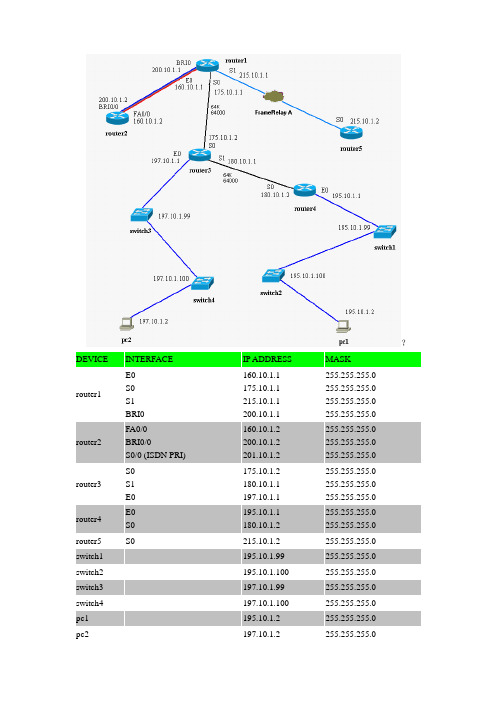
?router1E0S0S1BRI0160.10.1.1175.10.1.1215.10.1.1200.10.1.1255.255.255.0255.255.255.0255.255.255.0255.255.255.0router3S0S1E0175.10.1.2180.10.1.1197.10.1.1255.255.255.0255.255.255.0255.255.255.0router5S0215.10.1.2255.255.255.0 switch2-195.10.1.100255.255.255.0 switch4-197.10.1.100255.255.255.0 pc2-197.10.1.2255.255.255.0• Lab 1 - Basic Router Configuration• Lab 2 - Advanced Router Configuration• Lab 3 - CDP• Lab 4 - Telnet• Lab 5 - TFTP• Lab 6 - RIP• Lab 7 - IGRP• Lab 8 - EIGRP• Lab 9 - OSPF• Lab 10 – Catalyst 1900 Switch Configuration• Lab 11 - VLANs & Trunking (Catalyst 1900)• Lab 12 - Catalyst 2950 Switch Configuration• Lab 13 - VLANs and Trunking (Catalyst 2950)• Lab 14 - IP Access Lists• Lab 15 - NAT/PAT• Lab 16 - PPP & CHAP• Lab 17 - ISDN BRI-BRI using Legacy DDR• Lab 18 - ISDN BRI-BRI using Dialer Profiles• Lab 19 - ISDN PRI using Dialer Profiles• Lab 20 - Frame RelayLAB 1 – BASIC ROUTER CONFIGURATION1.In this lab, you will get practice with basic configuration and show commands on the Ciscorouter.在这个实验室里,实践思科路由器的基本配置和显示命令。
EIGRP收敛2

●当路由发生改变时,EIGRP需要重新收敛路由,这个过程由三个部分组成:输入事件、局部计算(包括查找可行的成功者路由)和使用动态查询来查找替代路由。
与路由收敛相关的EIGRP特性:●输入事件和局部计算典型的输入事件是:路由器从新的更新中学习到新的路由;路由器接口失效;邻接路由器失效。
局部计算的原理:当输入事件发生时,看路由器是否能够在局部找到替代路由。
其步骤如下:1)如果存在FS路由,则将最小metric的FS路由载入路由表,并发送更新到邻接路由器以通知新的路由。
2)如果没有FS路由,动态查询邻接路由器以获得新的路由。
要成为FS路由,首先需要满足可行性条件,其定义为:路由的RD值必须小于当前FD值。
如上拓扑结构,在R4上,最初选出的到172.31.211.0/24的成功者路由是经由R1,FD为(3+2+3)*256 = 2048(这里计算metric仅考虑delay),来自R1的RD = (3+2)*256 = 1280。
R4到达172.31.211.0/24的另一条路由是通过R2,其RD = (3+4)*256 = 1792。
如果R1失效,R4会首先检查局部是否有满足可行性条件的路由,显然,通过R2的路由的RD值(1792)小于当前FD值(2048),所以这时就可以选择这条路由为FS,将其载入路由表,并对外发布包含新路由的更新。
●动态查询路由当通过局部计算无法找出FS路由时,EIGRP路由器就只能采用动态方式向邻接路由器查询新路由。
首先路由器会改变其状态为active,此时EIGRP会多点传送查询(Query)消息到邻接路由器,邻接路由器接收到查询消息后,会返回单点EIGRP响应(Reply)包,在包中会标明是否它们存在到该子网的无环路由。
路由器学习接收到的所有Reply消息,更新其拓扑表,并重新计算已知路由和选择新的成功者。
如果仍然无法找到新的替代路由,路由器即认为到该子网无路由。
对邻接路由器而言,它们将任何接收到的Query消息看作输入事件,然后它们会采取如下步骤:1)如果路由器在其拓扑表中没有到那个子网的记录,它会发送EIGRP Reply包以表示其无路由。
2-RIP配置
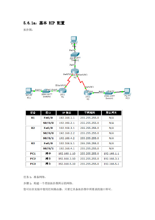
5.6.1a:基本 RIP 配置拓扑图:任务1:准备网络。
步骤1:构建一个类似拓扑图所示的网络。
您可以在实验中使用任何路由器,只要它具备拓扑图中所要求的接口即可。
注意:如果您使用1700、2500 或2600 路由器,则路由器输出和接口描述会与本文档中提供的有所不同。
步骤2:清除路由器上的现有配置。
进入路由器时,输入NO。
任务2:执行基本路由器配置。
根据下面的指导执行R1、R2 和R3 路由器的基本配置:1.配置路由器主机名。
2. 禁用DNS 查找。
3. 配置执行模式口令。
4. 配置当日消息标语。
5. 配置控制台连接的口令。
6. 配置VTY 连接的口令。
以上R1、R2、R3路由配置代码(如图):任务3:配置并激活串行地址和以太网地址。
步骤1:配置R1、R2 和R3 的接口。
使用拓扑图下方表格中的 IP 地址配置R1、R2 和R3 路由器上的接口。
R1(config)#interface F0/0R1(config-if)#ip address 192.168.1.1 255.255.255.0R1(config-if)#no sh%LINK-5-CHANGED: Interface FastEthernet0/0, changed state to up%LINEPROTO-5-UPDOWN: Line protocol on Interface FastEthernet0/0, changed state to upR1(config-if)#interface Serial0/0/0R1(config-if)#ip address 192.168.2.1 255.255.255.0R1(config-if)#clock rate 64000R1(config-if)#no sh%LINK-5-CHANGED: Interface Serial0/0/0, changed state to up%LINEPROTO-5-UPDOWN: Line protocol on Interface Serial0/0/0, changed state to up%SYS-5-CONFIG_I: Configured from console by consoleR2(config)#interface F0/0R2(config-if)#ip address 192.168.3.1 255.255.255.0R2(config-if)#no sh%LINK-5-CHANGED: Interface FastEthernet0/0, changed state to up%LINEPROTO-5-UPDOWN: Line protocol on Interface FastEthernet0/0, changed state to upR2(config-if)#interface Serial0/0/0R2(config-if)#ip address 192.168.2.2 255.255.255.0R2(config-if)#no sh%LINK-5-CHANGED: Interface Serial0/0/0, changed state to upR2(config-if)#interface Serial0/0/1R2(config-if)#ip address 192.168.4.2 255.255.255.0R2(config-if)#clock rate 64000R2(config-if)#no shu%LINEPROTO-5-UPDOWN: Line protocol on Interface Serial0/0/0, changed state to upR3(config)#interface F0/0R3(config-if)#ip address 192.168.5.1 255.255.255.0R3(config-if)#no sh%LINK-5-CHANGED: Interface Serial0/0/0, changed state to down%LINK-5-CHANGED: Interface FastEthernet0/0, changed state to up%LINEPROTO-5-UPDOWN: Line protocol on Interface FastEthernet0/0, changed state to upR3(config-if)#interface Serial0/0/0R3(config-if)#ip address 192.168.4.1 255.255.255.0R3(config-if)#no sh%LINK-5-CHANGED: Interface Serial0/0/0, changed state to down步骤2:检验IP 编址和接口。
CCNA实验教程
福建最好的培训中心福建最大的CISCO实验室3名CCIE,100多套CISCO设备PIX防火墙,3550交换机,7000路由器,两条ISDN线路基带MODEM,电话交换机,NETSCREEN防火墙登录微思实验室:远程: telnet://本地: telnet:192.168.10.251• Lab 1 - Basic Router Configuration• Lab 2 - Advanced Router Configuration• Lab 3 - CDP• Lab 4 - Telnet• Lab 5 - TFTP• Lab 6 - RIP• Lab 7 - IGRP• Lab 8 - EIGRP• Lab 9 - OSPF• Lab 10 – Catalyst 1900 Switch Configuration• Lab 11 - VLANs & Trunking (Catalyst 1900)• Lab 12 - Catalyst 2950 Switch Configuration• Lab 13 - VLANs and Trunking (Catalyst 2950)• Lab 13-1 Routing inter VLAN(Dot1q)• Lab 14 - IP Access Lists• Lab 15 - NAT/PAT• Lab 16 - PPP & CHAP• Lab 17 - ISDN BRI-BRI using Legacy DDR• Lab 18 - ISDN BRI-BRI using Dialer Profiles• Lab 19 - ISDN PRI using Dialer Profiles• Lab 20 - Frame RelayLAB 1 –基本配置3. 用户模式Router>4. Router> enable //用户模式敲入enable进入到特权模式Router#5. Router# ? //敲入问号看帮助6. Router# disable //特权模式敲入disable退到用户模式Router>7. Router> enable //用户模式敲入enable进入到特权模式Router# configure terminal //特权模式敲入configure terminal进入配置模式Router(config)# //配置模式8. 配置路由器名字(主机名)如…R1‟ (注:如果你用的实验台号是03,则命名为na03r1,如果为12,则命名na12r1,依次类推).Router(config)# hostname na12r1 //把第12号实验台的第一台路由器命名为na12r1na12r1(config)#9. 配置路由器的密码:●配置console 口密码:R1(config)#line console 0R1(config-line)#loginR1(config-line)#password ciscoR1(config-line)#设置密码后:00:29:42: %SYS-5-CONFIG_I: Configured from console by consoleUser Access VerificationPassword:Password: //这里要输入console口密码●配置enable 密码//从用户模式到enable模式的密码问题A: when both encrypted and unencrypted enable passwords are configured, which one is used?R1(config)# enable password cisco//密码显示为明文R1(config)# enable secret wisdom//密码为加密过的,显示为乱码注:用命令show running-config 可以看到密码cisco为明文,密码wisdom显示为乱码,当两个密码都配置时,只有enable secret所跟的密码生效,两个密码不可以配置一样的密码.配置vty密码//远程登陆telnet 的密码R1(config)#line vty 0 4R1(config-line)#loginR1(config-line)#password ciscoR1(config-line)#telnet命令的使用: telnet +IP address or hostname of a remote system例如: telnet 192.168.10.25110. 配置路由器接口ethernet0的IP address:R1>enableR1#configure terminalR1(config)#interface ethernet 0R1(config-if)#ip address 11.1.1.1 255.255.255.0R1(config-if)#no shutdown11. 在Serial0口配置R1(config-if)# int serial 0R1(config-if)# ip address 12.1.1.1 255.255.255.0R1(config-if)# no shutdown12. 测试ctrl-z的作用R1(config-if)# ctrl-z 任何模式下敲入ctrl-z都会退回到特权模式R1# 特权模式13. 退出路由器R1# logout 完全退出路由器14. 回到特权模式R1> enablepassword: cisco 输入enable secret 的密码为ciscoR1#15.显示接口的基本概况:R1# show ip interface brief16. 显示详细信息:show interface +接口类型+接口偏号例如:R1# show interfaces ethernet0 或是show interface serial 0R1#show interfaces ethernet 0Ethernet0 is up, line protocol is downHardware is Lance, address is 0000.0c92.8164 (bia 0000.0c92.8164)Internet address is 11.1.1.1/24MTU 1500 bytes, BW 10000 Kbit, DLY 1000 usec, rely 145/255, load 1/255 ……………….…………17.显示内存信息(也就是路由器正在运行的配置):R1# show running-config //当前正在远行的配置18. 显示NVRAM? If not, why not?R1# show startup-config 显示已经保存过的配置19. 保存配置:R1# copy running-config startup-config或是R1#write保存配置:copy running-config startup-config等同于write20. 现在显示NVRAM.R1# show startup-config21. 使用Show version:问题A: What IOS release is running在R1? 查看IOS的版本问题B: What are the contents of the configuration register? 查看寄存器的值R1# show version22. 查看运行的协议问题A:which protocols are currently running on the router?R1# show ip protocols23. 进入另一台Router.Router> enableRouter# configure terminalRouter(config)#24. 配置主机名,配置密码.Router(config)# hostname R2R2(config)# enable secret cisco25. 配置以太网IP.R2(config)# interface e0R2(config-if)# ip address 220.1.1.2 255.255.255.0R2(config-if)# no shutdown26. 显示所有接口简单信息R2(config-if)# ctrl-zR2# show ip interface briefR1#show ip interface briefInterface IP-Address OK? Method Status ProtocolEthernet0 11.1.1.1 YES manual up down Serial0 unassigned YES unset administratively down down Serial1 unassigned YES unset administratively down down3. 配置登陆信息Banner”Welcome to WISDOM LAB - Authorized Users Only”.R1(config)# banner motd #Welcome to WISDOM LAB - Authorized Users Only #4. 退出路由器,重新登录.R1# logoutenterpassword: ciscoR1> enablepassword: cisco6. 在R1上将R2和12.1.1.2对应起来(相当于Windows里的Hosts文件的作用)。
紫光恒越UNIS R3900 R5900综合业务网关接口模块手册说明书
UNIS R3900/R5900综合业务网关接口模块手册紫光恒越技术有限公司资料版本:6W113-20221130Copyright © 2022 紫光恒越技术有限公司及其许可者版权所有,保留一切权利。
未经本公司书面许可,任何单位和个人不得擅自摘抄、复制本书内容的部分或全部,并不得以任何形式传播。
UNIS为紫光恒越技术有限公司的商标。
对于本手册中出现的其它公司的商标、产品标识及商品名称,由各自权利人拥有。
由于产品版本升级或其他原因,本手册内容有可能变更。
紫光恒越保留在没有任何通知或者提示的情况下对本手册的内容进行修改的权利。
本手册仅作为使用指导,紫光恒越尽全力在本手册中提供准确的信息,但是紫光恒越并不确保手册内容完全没有错误,本手册中的所有陈述、信息和建议也不构成任何明示或暗示的担保。
前言UNIS R3900/R5900综合业务网关接口模块手册主要介绍了设备支持的接口类型、线缆连接和适配关系等内容。
前言部分包含如下内容:•读者对象•本书约定•产品配套资料•资料意见反馈读者对象本手册主要适用于如下工程师:•网络规划人员•现场技术支持与维护人员•负责网络配置和维护的网络管理员本书约定1. 命令行格式约定格式意义粗体命令行关键字(命令中保持不变、必须照输的部分)采用加粗字体表示。
斜体命令行参数(命令中必须由实际值进行替代的部分)采用斜体表示。
[ ] 表示用“[ ]”括起来的部分在命令配置时是可选的。
{ x | y | ... }表示从多个选项中仅选取一个。
[ x | y | ... ]表示从多个选项中选取一个或者不选。
{ x | y | ... } *表示从多个选项中至少选取一个。
[ x | y | ... ] *表示从多个选项中选取一个、多个或者不选。
&<1-n>表示符号&前面的参数可以重复输入1~n次。
# 由“#”号开始的行表示为注释行。
2. 图形界面格式约定格式意义< > 带尖括号“< >”表示按钮名,如“单击<确定>按钮”。
CCNP实验手册
CCNP Lab Manual IndexCCNP Lab ManualBuilding Scalable Cisco Internetworks CCNP Lab ManualLab 1.Configuring Basic EIGRP实验目的:1、掌握EIGRP的基本配置。
2、掌握EIGRP的通配符掩配置方法。
3、掌握EIGRP的自动汇总特性,以及如何关闭自动汇总。
4、掌握EIGRP的手工汇总。
实验拓扑图:实验步骤及要求:1、配置各台路由器的IP地址,并且使用ping命令确认各路由器的直连口的互通性。
2、在三台路由配置EIGRP自治系统编号为50。
3、登录到R2路由器,作如下配置(其它路由器参照其进行配置):、在任意一台路由器上观察EIGRP的邻居关系:其中:列H指出邻居学习的顺序,Address指出邻居地址,Interface指出邻居所在本地接口。
5、在任意一台路由器上查看路由器,确认路由:6、在R1路由器上使用更简洁的查看关于EIGRP的路由命令:7、我们注意到在R2路由器上有一条指向s1/0口的的汇总路由,这是EIGRP路由协议自动汇总的特性体现。
可以使用no auto-summary命令关闭。
如下:随后在R2上观察路由表的变化,如下显示:7、EIGRP也可以进行手工地址总结。
手工地址总结,可以有效的减少路由表的大小。
比如在R2上的路由中关于R3的.*.*的网络显示为四条具体路由,可以在R3上进行如下配置,减少路由通告条目。
、观察R2路由器的路由表:9、在R2上使用通配符掩码进行配置EIGRP:、在R2确认邻居,此处仅发现与R1建立了邻居关系。
11、查看R1的路由表,进行确认所学习到的路由。
12、实验完成。
CCNP Lab ManualLab 2.Configuring Default-network for EIGRP实验目的:1、掌握通过ip default-network命令配置EIGRP默认网络。
网络设备配置与管理实训指导
实验1 实验环境的安装与熟悉一、实验目的:1、掌握Packet Tracer5.3的安装及配置2、掌握Packet Tracer5.3的简单应用二、实验要求:按照实验指导书完成实验三、实验环境:PC+Packet Tracer5.0四、实验项目性质验证性实验五、实验要点1、Packet Tracer5.3的安装与配置2、Packet Tracer5.3的简单应用六、实验内容实验一、Packet Tracer5.3的安装及配置本实验的目的是练习Packet Tracer5.3的安装与配置,常见设置如语言包的设置、字体的设置等。
实验步骤:参考课堂演示实验二、Packet Tracer5.3的简单应用实验拓扑图如下:实验步骤:1、添加实验设备2、连接个设备之间的线路,注意用线的规则,并添加注释。
3、设置各台PC机的IP地址4、测试:各台PC机之间相互Ping对方看是否能通,如果不通原因是什么。
七、实验说明1、思考题:交换机与交换机之间用什么线?交换机与PC之间呢?PC与PC之间呢?PC与路由器之间呢?请通过实验验证。
2、实验报告要求:实验完毕后请按照要求填写实验报告实验2 路由器的配置模式与基本命令一、实验目的:1、掌握路由器的几种工作模式2、掌握路由器的基本管理二、实验要求:按照实验指导书完成实验三、实验环境:PC+Packet Tracer5.3四、实验项目性质验证性实验五、实验要点1、路由器工作模式2、路由器基本管理六、实验内容实验一、熟悉路由器的几种工作模式【以Cisco 2621XM为例】准备:拖动一台Cisco 2621XM路由器、一台PC到工作区中;建立两条连接:console口连接pc机与Cisco 2621XM路由器;通过网线连接PC机与Cisco 2621XM路由器。
1、熟悉路由器的7种模式【Setup模式、用户模式、特权模式、全局配置模式、接口配置模式、Line配置模式、Router配置模式】要点:路由器开机时会自动进入Setup模式,在特权模式下通过Setup命名也可进入该模式。
- 1、下载文档前请自行甄别文档内容的完整性,平台不提供额外的编辑、内容补充、找答案等附加服务。
- 2、"仅部分预览"的文档,不可在线预览部分如存在完整性等问题,可反馈申请退款(可完整预览的文档不适用该条件!)。
- 3、如文档侵犯您的权益,请联系客服反馈,我们会尽快为您处理(人工客服工作时间:9:00-18:30)。
ip authentication key-chain eigrp autonomous-system name-of-chain
Enables authentication of EIGRP packets using key in the keychain
Conห้องสมุดไป่ตู้iguring EIGRP MD5 Authentication (Cont.)
Hold Uptime SRTT (sec) (ms) 12 00:03:10 17
Q Seq Cnt Num 2280 0 14
RTO
Troubleshooting MD5 Authentication
R1#debug eigrp packets EIGRP Packets debugging is on (UPDATE, REQUEST, QUERY, REPLY, HELLO, IPXSAP, PROBE, ACK, STUB, SIAQUERY, SIAREPLY) *Jan 21 16:38:51.745: EIGRP: received packet with MD5 authentication, key id = 1 *Jan 21 16:38:51.745: EIGRP: Received HELLO on Serial0/0/1 nbr 192.168.1.102 *Jan 21 16:38:51.745: AS 100, Flags 0x0, Seq 0/0 idbQ 0/0 iidbQ un/rely 0/0 pe erQ un/rely 0/0 R2#debug eigrp packets EIGRP Packets debugging is on (UPDATE, REQUEST, QUERY, REPLY, HELLO, IPXSAP, PROBE, ACK, STUB, SIAQUERY, SIAREPLY) R2# *Jan 21 16:38:38.321: EIGRP: received packet with MD5 authentication, key id = 2 *Jan 21 16:38:38.321: EIGRP: Received HELLO on Serial0/0/1 nbr 192.168.1.101 *Jan 21 16:38:38.321: AS 100, Flags 0x0, Seq 0/0 idbQ 0/0 iidbQ un/rely 0/0 pe erQ un/rely 0/0
R2 Configuration for MD5 Authentication
<output omitted> key chain R2chain key 1 key-string firstkey accept-lifetime 04:00:00 Jan 1 2006 infinite send-lifetime 04:00:00 Jan 1 2006 infinite key 2 key-string secondkey accept-lifetime 04:00:00 Jan 1 2006 infinite send-lifetime 04:00:00 Jan 1 2006 infinite <output omitted> interface FastEthernet0/0 ip address 172.17.2.2 255.255.255.0 ! interface Serial0/0/1 bandwidth 64 ip address 192.168.1.102 255.255.255.224 ip authentication mode eigrp 100 md5 ip authentication key-chain eigrp 100 R2chain ! router eigrp 100 network 172.17.2.0 0.0.0.255 network 192.168.1.0 auto-summary
Optional: Specifies when key can be used for sending packets
Example MD5 Authentication Configuration
R1 Configuration for MD5 Authentication
<output omitted> key chain R1chain key 1 key-string firstkey accept-lifetime 04:00:00 Jan 1 2006 infinite send-lifetime 04:00:00 Jan 1 2006 04:01:00 Jan 1 2006 key 2 key-string secondkey accept-lifetime 04:00:00 Jan 1 2006 infinite send-lifetime 04:00:00 Jan 1 2006 infinite <output omitted> interface FastEthernet0/0 ip address 172.16.1.1 255.255.255.0 ! interface Serial0/0/1 bandwidth 64 ip address 192.168.1.101 255.255.255.224 ip authentication mode eigrp 100 md5 ip authentication key-chain eigrp 100 R1chain ! router eigrp 100 network 172.16.1.0 0.0.0.255 network 192.168.1.0 auto-summary
Simple Password vs. MD5 Authentication
Simple password authentication: – Router sends packet and key. – Neighbor checks whether key matches its key. – Process not secure. MD5 authentication: – Configure a key (password) and key ID; router generates a message digest, or hash, of the key, key ID and message. – Message digest is sent with packet; key is not sent. – Process OS secure.
Optional: Specifies when key will be accepted for received packets
Router(config-keychain-key)#
send-lifetime start-time {infinite | end-time | duration seconds}
MD5 Authentication
EIGRP MD5 authentication:
Router generates a message digest, or hash, of the key, key ID, and message. EIGRP allows keys to be managed using key chains. Specify key ID (number), key, and lifetime of key. First valid activated key, in order of key numbers, is used.
Router(config)#
key chain name-of-chain
Enters configuration mode for the keychain
Router(config-keychain)#
key key-id
Identifies key and enters configuration mode for the keyid
Configuring EIGRP MD5 Authentication (Cont.)
Router(config-keychain-key)#
key-string text
Identifies key string (password)
Router(config-keychain-key)#
accept-lifetime start-time {infinite | end-time | duration seconds}
Configuring EIGRP
Configuring EIGRP Authentication
Router Authentication
Many routing protocols support authentication such that a router authenticates the source of each routing update packet that it receives. Simple password authentication is supported by: – IS-IS – OSPF – RIPv2 MD5 authentication is supported by: – OSPF – RIPv2 – BGP – EIGRP
0 192.168.1.102 Se0/0/1 R1#show ip route <output omitted> Gateway of last resort is not set D 172.17.0.0/16 [90/40514560] via 192.168.1.102, 00:02:22, Serial0/0/1 172.16.0.0/16 is variably subnetted, 2 subnets, 2 masks D 172.16.0.0/16 is a summary, 00:31:31, Null0 C 172.16.1.0/24 is directly connected, FastEthernet0/0 192.168.1.0/24 is variably subnetted, 2 subnets, 2 masks C 192.168.1.96/27 is directly connected, Serial0/0/1 D 192.168.1.0/24 is a summary, 00:31:31, Null0 R1#ping 172.17.2.2 Type escape sequence to abort. Sending 5, 100-byte ICMP Echos to 172.17.2.2, timeout is 2 seconds: !!!!! Success rate is 100 percent (5/5), round-trip min/avg/max = 12/15/16 ms