Board Size
Python飞行棋游戏代码

Python飞行棋游戏代码飞行棋游戏涉及到游戏逻辑、界面设计等多个方面,这里仅提供一个简单的Python飞行棋游戏框架,使用pygame库实现。
要运行此代码,请确保已安装pygame库。
import pygameimport sysimport random# 初始化pygamepygame.init()# 设置窗口大小screen_width = 800screen_height = 600screen = pygame.display.set_mode((screen_width, screen_height))# 设置标题pygame.display.set_caption("飞行棋")# 加载背景图片background = pygame.image.load("background.png")# 加载棋子图片player = pygame.image.load("player.png")opponent = pygame.image.load("opponent.png")# 设置棋盘格子大小grid_size = 40# 创建棋盘board = [[0 for _ in range(grid_size)] for _ in range(grid_size)]# 随机放置玩家和对手棋子player_pos = random.randint(0, grid_size - 1), random.randint(0, grid_size - 1)opponent_pos = random.randint(0, grid_size - 1), random.randint(0, grid_size - 1)while player_pos == opponent_pos:opponent_pos = random.randint(0, grid_size - 1), random.randint(0, grid_size - 1)# 将棋子图片放置在棋盘格子上board[player_pos[0]][player_pos[1]] = playerboard[opponent_pos[0]][opponent_pos[1]] = opponent# 游戏主循环turn = 1while True:# 处理事件for event in pygame.event.get():if event.type == pygame.QUIT:pygame.quit()sys.exit()elif event.type == pygame.MOUSEBUTTONDOWN:x, y = event.posrow, col = x // grid_size, y // grid_sizeif board[row][col] == 0:board[row][col] = turn % 2turn += 1# 清屏screen.blit(background, (0, 0))# 绘制棋盘格子for i in range(grid_size):for j in range(grid_size):pygame.draw.rect(screen, (255, 255, 255), (i * grid_size, j * grid_size, grid_size, grid_size), 1)if board[i][j] == 1:pygame.draw.circle(screen, (0, 0, 255), (i * grid_size + grid_size // 2, j * grid_size + grid_size // 2), 10)elif board[i][j] == 2:pygame.draw.circle(screen, (255, 0, 0), (i * grid_size + grid_size // 2, j * grid_size + grid_size // 2), 10)# 更新屏幕pygame.display.update()请注意,这个代码仅仅实现了一个非常简化的飞行棋游戏,只有一个可以移动的棋子。
Wire-to-Board Connector(线对板连接器)
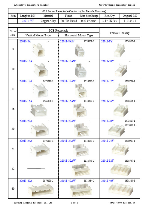
PCB Receptacle Vertical Mount Type
25422-32A
966658-1 964824-1
Horizontal Mount Type
Female Housing
25422-32Y
1J0972977C 1719057-1 1719058-1 1719059-1
32
25423-32A 32
46042-24Y 46043-24Y
316371-1 316372-6
36
25051-5AW 5
7382-5841
25051-5Y
7283-5830
25051-10AW 10
-
25051-10Y
7283-5831
25051-14AW 14
7382-5842
25051-14Y
7283-5832
25060-28A
No.of Pos.
PCB Receptacle Vertical Mount Type Horizontal Mount Type
35055-8AW
173856-1
Female Housing
35055-8Y
173850-1
8
35055-12A 12
1-174957-1
35055-12Y
173851-1
No.of Pos.
PCB Receptacle Vertical Mount Type Horizontal Mount Type
50011-12AW
827229-1
Female Housing
50011-12Y
827603-1 927458-1 927084-1
12
PowerFlex

Installation Instructions PowerFlex ® 700S Phase I to Phase II Conversion - Frames 9 - 11What This Kit Includes•Phase II Main Control circuit board and assembly (ordered separately)•Phase II Control Assembly mounting bracket and hardware •40 position ribbon cable •30 position ribbon cable •Control communication cable •Power Interface PCB and hardware •V oltage Feedback PCB and hardware Tools That You Need •Phillips ® screwdriver•POZIDRIV ® screwdriverPhillips ® and POZIDRIV ® are registered trademarks of Phillips Screw Company.!ATTENTION: To avoid an electric shock hazard, ensure that all power to the drive has been removed before performing the following.!ATTENTION: To avoid an electric shock hazard, verify that the voltage on the bus capacitors has discharged before performing any work on the drive. Measure the DC bus voltage at the DC+ & DC- terminals. The voltage must be zero.!ATTENTION: HOT surfaces can cause severe burns. Do not touch the heatsink surface during operation of the drive. After disconnecting power allow time for cooling.!ATTENTION: Hazard of permanent eye damage exists when using optical transmission equipment. This product emits intense light and invisible radiation. Do not look into SynchLink fiber-optic ports or SynchLink fiber-optic cable connectors.!ATTENTION: This drive contains ESD (Electrostatic Discharge) sensitive parts and assemblies. Static control precautions are required when installing, testing, servicing or repairing this assembly. Component damage may result if ESD control procedures are not followed. If you are not familiar with static control procedures, reference A-B publication 8000-4.5.2, “Guarding Against Electrostatic Damage” or any other applicable ESD protection handbook.2PowerFlex® 700S Phase I to Phase II Conversion - Frames 9 - 11What You Need to DoTo install the PowerFlex® 700S Phase I to Phase II hardware conversion kit:❐ Step 1:Remove power from the drive ❐ Step 2:Open drive ❐ Step 3:Remove Phase I Main Control circuit board ❐ Step 4:Remove Phase I Power Interface circuit board ❐ Step 5:Install Phase II Power Interface circuit board ❐ Step 6:Remove Phase I V oltage Feedback circuit board ❐ Step 7:Install Phase II V oltage Feedback circuit board ❐ Step 8:Install Phase II Main Control assembly mounting bracket ❐ Step 9:Install Phase II Main Control assembly ❐ Step 10:Make Main Control circuit board connections ❐ Step 11:Document changeStep 1:Removing Powerfrom the Drive 1.Turn off and lock out input power. Wait five minutes.2.Verify that there is no voltage at the drive’s input power terminals.3.Measure the DC bus voltage at the DC+ & DC- terminals on the Power Terminal Block. The voltage must be zero.!ATTENTION: To avoid an electric shock hazard, verify that thevoltage on the bus capacitors has discharged before performingany work on the drive. Measure the DC bus voltage at the +DC &–DC terminals of the Power Terminal Block. The voltage mustbe zero.Remove power before making or breaking cable connections.When you remove or insert a cable connector with powerapplied, an electrical arc may occur. An electrical arc can causepersonal injury or property damage by:•sending an erroneous signal to your system’s field devices,causing unintended machine motion•causing an explosion in a hazardous environmentElectrical arcing causes excessive wear to contacts on both themodule and its mating connector. Worn contacts may create electrical resistance.PowerFlex® 700S Phase I to Phase II Conversion - Frames 9 - 113 Step 2:Opening the Drive Frame 9 Size Drives•Remove the (8) screws from the top cover and remove it.Frame 10 & 11 Size Drives•Open the enclosure door.Step 3:Removing the Phase I Main Control Circuit Board Frame 9 Size DrivesImportant:Before removing connections and wires, mark the connections and wires to avoid incorrect wiring during assembly.1.On the 700S Main Control assembly:–Unplug the I/O and SynchLink cables from the Main Control circuit board–Unplug the feedback wiring from Feedback Option card–Unplug the communication cables from DriveLogix™ controller!ATTENTION: Hazard of permanent eye damage exists whenusing optical transmission equipment. This product emits intenselight and invisible radiation. Do not look into SynchLinkfiber-optic ports or SynchLink fiber-optic cable connectors.4PowerFlex® 700S Phase I to Phase II Conversion - Frames 9 - 112.Unplug the ribbon cables from J2 and J7 on the Main Control circuitboard. The 72-position cable connected to J2 should be discarded and the10-position cable connected to J7 should be retained for reuse.Note: If the DriveLogix™ option is installed, the J2 and J7 connectionsfor the ribbon cables will be located behind the DriveLogix controller.3.Remove the three screws that hold the control bracket and Phase I MainControl circuit board to the control frame.4.Remove the control bracket and Phase I Main Control circuit board.5.Loosen the captive screw and swing the control assembly away fromdrive.Frame 10 & 11 Size DrivesImportant:Before removing connections and wires, mark the connectionsand wires to avoid incorrect wiring during assembly.!ATTENTION: Hazard of permanent eye damage exists when using optical transmission equipment. This product emits intense light and invisible radiation. Do not look into fiber-optic ports or fiber-optic cable connectors.PowerFlex® 700S Phase I to Phase II Conversion - Frames 9 - 115 1.Loosen the captive screw and swing the control assembly away fromdrive.2.On the 700S control assembly:–Unplug the I/O and SynchLink cables from the Main Control Board –Unplug the feedback wiring from Feedback Option card–Unplug communication cables from DriveLogix™ controller3.Unplug the ribbon cables from J2 and J7 on the Main Control circuitboard.Note: If the DriveLogix option is installed, the J2 and J7 connections for the ribbon cables will be located behind the DriveLogix controller.4.Remove the three screws that hold the control bracket and Phase I MainControl circuit board to the control frame.5.Remove the control bracket and Phase I Main Control circuit board.6PowerFlex® 700S Phase I to Phase II Conversion - Frames 9 - 11Step 4:Removing the Phase I Power Interface Circuit Board Frame 9 Size DrivesImportant:Before removing connections and wires, mark the connections and wires to avoid incorrect wiring during assembly.1.Carefully disconnect the fiber-optic cables from sockets along the rightside of the Power Interface circuit board and carefully set them aside.Important:Minimum inside bend radius for fiber-optic cable is 25.4 mm (1 in.). Any bends with a shorter inside radius canpermanently damage the fiber-optic cable. Signalattenuation increases with decreased inside bend radii.2.Disconnect the cables from sockets J3 and J17 on the Power Interfacecircuit board and set them aside. The 72-position cable connected to J3 should be discarded and the 10-position cable connected to J17 should be retained for reuse.3.Remove the five screws that hold the Power Interface circuit board to thecontrol frame.4.Remove the Power Interface circuit board from the control frame.!ATTENTION: Hazard of permanent eye damage exists whenusing optical transmission equipment. This product emits intenselight and invisible radiation. Do not look into fiber-optic ports orfiber-optic cable connectors.SocketsPowerFlex® 700S Phase I to Phase II Conversion - Frames 9 - 117Frame 10 & 11 Size DrivesImportant:Before removing connections and wires, mark the connectionsand wires to avoid incorrect wiring during assembly.1.Carefully disconnect the fiber-optic cables from sockets along the right side of the Power Interface circuit board (on the backside of the control assembly), and carefully set them aside.Important:Minimum inside bend radius for fiber-optic cable is 25.4mm (1 in.). Any bends with a shorter inside radius canpermanently damage the fiber-optic cable. Signalattenuation increases with decreased inside bend radii.2.Disconnect the cables from sockets J3 and J17 on the Power Interface circuit board and set them aside. The 72-position cable connected to J3 should be discarded and the 10-position cable connected to J17 should be retained for reuse.3.Remove the five screws that hold the Power Interface circuit board and insulator board to the five standoffs on the control bracket.4.Remove the Power Interface circuit board from the control frame. Save the insulator board below the Power Interface circuit board for reuse.!ATTENTION: Hazard of permanent eye damage exists whenusing optical transmission equipment. This product emits intenselight and invisible radiation. Do not look into fiber-optic ports or fiber-optic cable connectors.8PowerFlex® 700S Phase I to Phase II Conversion - Frames 9 - 11Step 5:Installing the Phase II Power Interface Circuit Board 1.Install the 700S Phase II Power Interface circuit board in reverse order ofremoval. Tighten screws to 0.9 N-m (8 lb.-in.).Important:For frame 9 size drives, the 10-position ribbon cableconnected to J17 on the Power Interface circuit board shouldbe routed under the board.Step 6:Removing the Phase I Voltage Feedback Circuit Board Frame 9 Size Drives1.Remove the four screws that hold the clear plastic shield to the standoffsand remove the shield.2.Carefully disconnect the fiber-optic cables from sockets J4 and J5 of theV oltage Feedback circuit board, and carefully set them aside.!ATTENTION: Hazard of permanent eye damage exists whenusing optical transmission equipment. This product emits intenselight and invisible radiation. Do not look into fiber-optic ports orfiber-optic cable connectors.PowerFlex® 700S Phase I to Phase II Conversion - Frames 9 - 119 Important:Minimum inside bend radius for fiber-optic cable is 25.4 mm (1 in.). Any bends with a shorter inside radius canpermanently damage the fiber-optic cable. Signalattenuation increases with decreased inside bend radii.3.Disconnect the cables from sockets J1, J2 and J8 on the V oltageFeedback circuit board.4.Remove the five standoffs that support the clear plastic shield and securethe V oltage Feedback circuit board to its mounting plate.5.Remove the V oltage Feedback circuit board from its mounting plate.10PowerFlex® 700S Phase I to Phase II Conversion - Frames 9 - 11Frame 10 & 11 Size DrivesOn frame 10 &11 size drives you must move the control frame, the airflowplate and the protective covers before you can remove the V oltage Feedbackcircuit board.Removing the Control Frame, Airflow Plate and Protective Covers on Frame 10 & 11Drives1.Loosen the T8 Torx-head screws that hold the control frame to the driveenclosure (remove screws on early frame 10 drives).2.Swing the control frame out and away from the power structure.order to swing-open the control frame.PowerFlex® 700S Phase I to Phase II Conversion - Frames 9 - 1111 3.Remove the T8 Torx-head screws which secure the airflow plate to thedrive.4.Slide the airflow plate off of drive.12PowerFlex® 700S Phase I to Phase II Conversion - Frames 9 - 115.Remove the four M5 POZIDRIV screws that hold the top and bottomprotective covers to the main front protective cover, then remove the topand bottom protective covers.6.Remove the four M5 POZIDRIV screws that hold the main frontprotective cover to the drive, then remove the protective cover.Note: The two (2) side protective covers do not need to be removed forthis installation.PowerFlex® 700S Phase I to Phase II Conversion - Frames 9 - 1113Removing 700S Voltage Feedback circuit board on Frame 10 & 11 Drives7.Carefully disconnect the fiber-optic cables from J4 and J5 sockets alongthe top of the V oltage Feedback circuit board, and carefully set themaside.Important:Minimum inside bend radius for fiber-optic cable is 25.4mm (1 in.). Any bends with a shorter inside radius canpermanently damage the fiber-optic cable. Signalattenuation increases with decreased inside bend radii.8.Disconnect the cables from sockets J1, J2 and J8 on the V oltageFeedback circuit board.9.Remove the five screws that hold the V oltage Feedback circuit board tothe drive.10.Remove the circuit board from the drive.!ATTENTION: Hazard of permanent eye damage exists whenusing optical transmission equipment. This product emits intenselight and invisible radiation. Do not look into fiber-optic ports orfiber-optic cable connectors.14PowerFlex® 700S Phase I to Phase II Conversion - Frames 9 - 11Step 7:Installing the Phase II Voltage Feedback Circuit Board 1.Install the Phase II V oltage Feedback circuit board in reverse order ofremoval. Tighten screws to 0.9 N-m (8 lb.-in.).Important:For frame 9 size drives, the plastic protective cover must be re-installed.2.For frame 10 & 11 size drives only, install the protective covers, theairflow plate and the control frame in reverse order of removal as in Step 6: Removing the Phase I V oltage Feedback Circuit Board on page8.Step 8:Installing the Phase II Main Control Assembly Mounting Bracket 1.Insert the two (2) screws for the mounting bracket into the holes in thecontrol assembly but do not tighten.2.Slide the slots of the mounting bracket onto the screws on the controlassembly and tighten the screws.Frame 10 & 11 Size Drives ShownPowerFlex® 700S Phase I to Phase II Conversion - Frames 9 - 1115Step 9:Installing the Phase II Main Control Assembly 1.Slide the Phase II Main Control assembly onto the mounting bracket andtighten the two (2) mounting screws.Important:For frame 9 size drives, the 10-position connector routed under the Power Interface circuit board, connected to P6 on the MainControl circuit board, should be routed under the control frameand connect to the back of the Main control circuit board. Referto Step 5 Installing the Phase II Power Interface CircuitBoard on page8 for routing illustration.Step 10:Making the Main Control Circuit Board Connections 1.Connect the 10-position ribbon cable from J17 on the Power Interfacecircuit board to P6 on the Main Control circuit board.2.Connect J1 on the Power Interface Board to P2 on the Main Controlcircuit board and J2 on the Power Interface Board to P1 on the Main Control circuit board.3.Install all other connections on the Main Control assembly.Refer to publication 20D-AT001, PowerFlex 700S Conversion Guide - Phase I to Phase II, for information about reconnecting I/O wiring. This publication also contains information regarding the compatibility of older feedback and communications options with the new Phase II drive.Feedback option cards from drives with Phase I control are not compatible with drives with Phase II control.DPI communication adapters and NetLinx communication daughtercards from drives with Phase I control are compatible with drives with Phase IIcontrol.Frame 10 & 11 DrivesShown16PowerFlex® 700S Phase I to Phase II Conversion - Frames 9 - 11Step 11:Documenting the Change 1.Record the modification on the Field Installed Option label.2.Replace the covers and close the enclosure door in the reverse order asindicated in Step 2: Opening the Drive.PowerFlex® 700S Phase I to Phase II Conversion - Frames 9 - 1117 Related Documentation Allen-Bradley publications are available on the internet at/literature.For Read this document Document number Information on converting from Phase I PowerFlex 700Sand DriveLogix5720 to Phase II PowerFlex 700S andDriveLogix5730PowerFlex 700S Conversion Guide - Phase I to Phase II20D-AT001In depth information regarding the operation of PowerFlex700S Phase II drivesPowerFlex 700S with Phase II Control User Guide20D-UM006Information on the installation of the Stegmann Feedback Option Card Installation Instructions - Stegmann Feedback Option Cardfor PowerFlex 700S Drives20D-IN001Information on the installation of the Resolver Feedback Option Card Installation Instructions - Resolver Feedback Option Cardfor PowerFlex 700S Drives20D-IN002Information on the installation of the Multi Device Interface Option Card Installation Instructions - Multi Device Interface OptionCard for PowerFlex 700S Drives20D-IN004Information on the installation of the SynchLink Board for PowerFlex 700S Drives with Phase II Control Installation Instructions - SynchLink Board for PowerFlex700S Drives with Phase II Control20D-IN010Information on the installation of the Second Encoder Option Card for Phase II Installation Instructions - Second Encoder Option Card forPhase II20D-IN009Information on the installation of the Embedded EtherNet/ IP Option for 700S Phase II Installation Instructions - Embedded EtherNet/IP Option for700S Phase II20D-IN011Information on the installation of the Embedded EtherNet/ IP Option for DriveLogix5730Installation Instructions - Embedded EtherNet/IP Option for DriveLogix573020D-IN012Information on the installation of the Logix Expansion Board for DriveLogix5730Installation Instructions - Logix Expansion Board forDriveLogix573020D-IN013Information on the installation of the DriveLogix5730Upgrade KitInstallation Instructions - DriveLogix5730 Upgrade Kit20D-IN015Information on the installation of the DriveGuard Safe-Off with Second Encoder for 700S Phase II Installation Instructions - DriveGuard Safe-Off with Second Encoder for 700S Phase II20D-IN016Information on the installation of the Heidenhain Feedback Option Card Installation Instructions - Heidenhain Feedback OptionCard for PowerFlex 700S Drives20D-IN017Notes:Publication 20D-IN019A-EN-P - October 2005P/N 373249-P01Copyright © 2005 Rockwell Automation. All rights reserved. Printed in USA.。
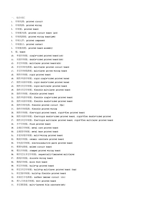
线路板英语词汇

一、综合词汇1、印制电路:printed circuit2、印制线路:printed wiring3、印制板:printed board4、印制板电路:printed circuit board (pcb)5、印制线路板:printed wiring board(pwb)6、印制元件:printed component7、印制接点:printed contact8、印制板装配:printed board assembly9、板:board10、单面印制板:single-sided printed board(ssb)11、双面印制板:double-sided printed board(dsb)12、多层印制板:multilayer printed board(mlb)13、多层印制电路板:multilayer printed circuit board14、多层印制线路板:multilayer printed wiring board15、刚性印制板:rigid printed board16、刚性单面印制板:rigid single-sided printed broad17、刚性双面印制板:rigid double-sided printed broad18、刚性多层印制板:rigid multilayer printed board19、挠性多层印制板:flexible multilayer printed board20、挠性印制板:flexible printed board21、挠性单面印制板:flexible single-sided printed board22、挠性双面印制板:flexible double-sided printed board23、挠性印制电路:flexible printed circuit (fpc)24、挠性印制线路:flexible printed wiring25、刚性印制板:flex-rigid printed board, rigid-flex printed board26、刚性双面印制板:flex-rigid double-sided printed board, rigid-flex double-sided printed27、刚性多层印制板:flex-rigid multilayer printed board, rigid-flex multilayer printed board28、齐平印制板:flush printed board29、金属芯印制板:metal core printed board30、金属基印制板:metal base printed board31、多重布线印制板:multi-wiring printed board32、陶瓷印制板:ceramic substrate printed board33、导电胶印制板:electro conductive paste printed board34、模塑电路板:molded circuit board35、模压印制板:stamped printed wiring board36、顺序层压多层印制板:sequentially-laminated multilayer37、散线印制板:discrete wiring board38、微线印制板:micro wire board39、积层印制板:build-up printed board40、积层多层印制板:build-up multilayer printed board (bum)41、积层挠印制板:build-up flexible printed board42、表面层合电路板:surface laminar circuit (slc)43、埋入凸块连印制板:b2it printed board44、多层膜基板:multi-layered film substrate(mfs)45、层间全内导通多层印制板:alivh multilayer printed board46、载芯片板:chip on board (cob)47、埋电阻板:buried resistance board48、母板:mother board49、子板:daughter board50、背板:backplane51、裸板:bare board52、键盘板夹心板:copper-invar-copper board53、动态挠性板:dynamic flex board54、静态挠性板:static flex board55、可断拼板:break-away planel56、电缆:cable57、挠性扁平电缆:flexible flat cable (ffc)58、薄膜开关:membrane switch59、混合电路:hybrid circuit60、厚膜:thick film61、厚膜电路:thick film circuit62、薄膜:thin film63、薄膜混合电路:thin film hybrid circuit64、互连:interconnection65、导线:conductor trace line66、齐平导线:flush conductor67、传输线:transmission line68、跨交:crossover69、板边插头:edge-board contact70、增强板:stiffener71、基底:substrate72、基板面:real estate73、导线面:conductor side74、元件面:component side75、焊接面:solder side76、印制:printing77、网格:grid78、图形:pattern79、导电图形:conductive pattern80、非导电图形:non-conductive pattern81、字符:legend82、标志:mark二、基材:1、基材:base material2、层压板:laminate3、覆金属箔基材:metal-clad bade material4、覆铜箔层压板:copper-clad laminate (ccl)5、单面覆铜箔层压板:single-sided copper-clad laminate6、双面覆铜箔层压板:double-sided copper-clad laminate7、复合层压板:composite laminate8、薄层压板:thin laminate9、金属芯覆铜箔层压板:metal core copper-clad laminate10、金属基覆铜层压板:metal base copper-clad laminate11、挠性覆铜箔绝缘薄膜:flexible copper-clad dielectric film12、基体材料:basis material13、预浸材料:prepreg14、粘结片:bonding sheet15、预浸粘结片:preimpregnated bonding sheer16、环氧玻璃基板:epoxy glass substrate17、加成法用层压板:laminate for additive process18、预制内层覆箔板:mass lamination panel19、内层芯板:core material20、催化板材:catalyzed board ,coated catalyzed laminate21、涂胶催化层压板:adhesive-coated catalyzed laminate22、涂胶无催层压板:adhesive-coated uncatalyzed laminate23、粘结层:bonding layer24、粘结膜:film adhesive25、涂胶粘剂绝缘薄膜:adhesive coated dielectric film26、无支撑胶粘剂膜:unsupported adhesive film27、覆盖层:cover layer (cover lay)28、增强板材:stiffener material29、铜箔面:copper-clad surface30、去铜箔面:foil removal surface31、层压板面:unclad laminate surface32、基膜面:base film surface33、胶粘剂面:adhesive face34、原始光洁面:plate finish35、粗面:matt finish36、纵向:length wise direction37、模向:cross wise direction38、剪切板:cut to size panel39、酚醛纸质覆铜箔板:phenolic cellulose paper copper-clad laminates(phenolic/paper ccl)40、环氧纸质覆铜箔板:epoxide cellulose paper copper-clad laminates (epoxy/paper ccl)41、环氧玻璃布基覆铜箔板:epoxide woven glass fabric copper-clad laminates42、环氧玻璃布纸复合覆铜箔板:epoxide cellulose paper core, glass cloth surfaces copper-clad laminates43、环氧玻璃布玻璃纤维复合覆铜箔板:epoxide non woven/woven glass reinforced copper-clad laminates44、聚酯玻璃布覆铜箔板:ployester woven glass fabric copper-clad laminates45、聚酰亚胺玻璃布覆铜箔板:polyimide woven glass fabric copper-clad laminates46、双马来酰亚胺三嗪环氧玻璃布覆铜箔板:bismaleimide/triazine/epoxide woven glass fabric copper-clad laminates47、环氧合成纤维布覆铜箔板:epoxide synthetic fiber fabric copper-clad laminates48、聚四乙烯玻璃纤维覆铜箔板:teflon/fiber glass copper-clad laminates49、超薄型层压板:ultra thin laminate50、陶瓷基覆铜箔板:ceramics base copper-clad laminates51、紫外线阻挡型覆铜箔板:uv blocking copper-clad laminates三、基材的材料1、a阶树脂:a-stage resin2、b阶树脂:b-stage resin3、c阶树脂:c-stage resin4、环氧树脂:epoxy resin5、酚醛树脂:phenolic resin6、聚酯树脂:polyester resin7、聚酰亚胺树脂:polyimide resin8、双马来酰亚胺三嗪树脂:bismaleimide-triazine resin9、丙烯酸树脂:acrylic resin10、三聚氰胺甲醛树脂:melamine formaldehyde resin11、多官能环氧树脂:polyfunctional epoxy resin12、溴化环氧树脂:brominated epoxy resin13、环氧酚醛:epoxy novolac14、氟树脂:fluroresin15、硅树脂:silicone resin16、硅烷:silane17、聚合物:polymer18、无定形聚合物:amorphous polymer19、结晶现象:crystalline phenomena20、双晶现象:dimorphism21、共聚物:copolymer22、合成树脂:synthetic23、热固性树脂:thermosetting resin24、热塑性树脂:thermoplastic resin25、感光性树脂:photosensitive resin26、环氧当量:weight per epoxy equivalent (wpe)27、环氧值:epoxy value28、双氰胺:dicyandiamide29、粘结剂:binder30、胶粘剂:adhesive31、固化剂:curing agent32、阻燃剂:flame retardant33、遮光剂:opaque34、增塑剂:plasticizers35、不饱和聚酯:unsatuiated polyester36、聚酯薄膜:polyester37、聚酰亚胺薄膜:polyimide film (pi)38、聚四氟乙烯:polytetrafluoetylene (ptfe)39、聚全氟乙烯丙烯薄膜:perfluorinated ethylene-propylene copolymer film (fep)40、增强材料:reinforcing material41、玻璃纤维:glass fiber42、e玻璃纤维:e-glass fibre43、d玻璃纤维:d-glass fibre44、s玻璃纤维:s-glass fibre45、玻璃布:glass fabric46、非织布:non-woven fabric47、玻璃纤维垫:glass mats48、纱线:yarn49、单丝:filament50、绞股:strand51、纬纱:weft yarn52、经纱:warp yarn53、但尼尔:denier54、经向:warp-wise55、纬向:weft-wise, filling-wise56、织物经纬密度:thread count57、织物组织:weave structure58、平纹组织:plain structure59、坏布:grey fabric60、稀松织物:woven scrim61、弓纬:bow of weave62、断经:end missing63、缺纬:mis-picks64、纬斜:bias65、折痕:crease66、云织:waviness67、鱼眼:fish eye68、毛圈长:feather length69、厚薄段:mark70、裂缝:split71、捻度:twist of yarn72、浸润剂含量:size content73、浸润剂残留量:size residue74、处理剂含量:finish level75、浸润剂:size76、偶联剂:couplint agent77、处理织物:finished fabric78、聚酰胺纤维:polyarmide fiber79、聚酯纤维非织布:non-woven polyester fabric80、浸渍绝缘纵纸:impregnating insulation paper81、聚芳酰胺纤维纸:aromatic polyamide paper82、断裂长:breaking length83、吸水高度:height of capillary rise84、湿强度保留率:wet strength retention85、白度:whiteness86、陶瓷:ceramics87、导电箔:conductive foil88、铜箔:copper foil89、电解铜箔:electrodeposited copper foil (ed copper foil)90、压延铜箔:rolled copper foil91、退火铜箔:annealed copper foil92、压延退火铜箔:rolled annealed copper foil (ra copper foil)93、薄铜箔:thin copper foil94、涂胶铜箔:adhesive coated foil95、涂胶脂铜箔:resin coated copper foil (rcc)96、复合金属箔:composite metallic material97、载体箔:carrier foil98、殷瓦:invar99、箔(剖面)轮廓:foil profile100、光面:shiny side101、粗糙面:matte side102、处理面:treated side103、防锈处理:stain proofing104、双面处理铜箔:double treated foil四、设计1、原理图:elements diagram2、逻辑图:logic diagram3、印制线路布设:printed wire layout4、布设总图:master drawing5、可制造性设计:design-for-manufacturability6、计算机辅助设计:computer-aided design.(cad)7、计算机辅助制造:computer-aided manufacturing.(cam)8、计算机集成制造:computer integrate manufacturing.(cim)9、计算机辅助工程:computer-aided engineering.(cae)10、计算机辅助测试:computer-aided test.(cat)11、电子设计自动化:electric design automation .(eda)12、工程设计自动化:engineering design automaton .(eda2)13、组装设计自动化:assembly aided architectural design. (aaad)14、计算机辅助制图:computer aided drawing15、计算机控制显示:computer controlled display .(ccd)16、布局:placement17、布线:routing18、布图设计:layout19、重布:rerouting20、模拟:simulation21、逻辑模拟:logic simulation22、电路模拟:circuit simulation23、时序模拟:timing simulation24、模块化:modularization25、布线完成率:layout efficiency26、机器描述格式:machine description format .(mdf)27、机器描述格式数据库:mdf database28、设计数据库:design database29、设计原点:design origin30、优化(设计):optimization (design)31、供设计优化坐标轴:predominant axis32、表格原点:table origin33、镜像:mirroring34、驱动文件:drive file35、中间文件:intermediate file36、制造文件:manufacturing documentation37、队列支撑数据库:queue support database38、元件安置:component positioning39、图形显示:graphics display40、比例因子:scaling factor41、扫描填充:scan filling42、矩形填充:rectangle filling43、填充域:region filling44、实体设计:physical design45、逻辑设计:logic design46、逻辑电路:logic circuit47、层次设计:hierarchical design48、自顶向下设计:top-down design49、自底向上设计:bottom-up design50、线网:net51、数字化:digital52、设计规则检查:design rule checking53、走(布)线器:router (cad)54、网络表:net list55、计算机辅助电路分析:computer-aided circuit analysis56、子线网:subnet57、目标函数:objective function58、设计后处理:post design processing (pdp)59、交互式制图设计:interactive drawing design60、费用矩阵:cost matrix61、工程图:engineering drawing62、方块框图:block diagram63、迷宫:maze64、元件密度:component density65、巡回售货员问题:traveling salesman problem66、自由度:degrees freedom67、入度:out going degree68、出度:incoming degree69、曼哈顿距离:Manhantton distance70、欧几里德距离:Euclidean distance71、网络:network72、阵列:array73、段:segment74、逻辑:logic75、逻辑设计自动化:logic design automation76、分线:separated time77、分层:separated layer78、定顺序:definite sequence五、形状与尺寸:1、导线(通道):conduction (track)2、导线(体)宽度:conductor width3、导线距离:conductor spacing4、导线层:conductor layer5、导线宽度/间距:conductor line/space6、第一导线层:conductor layer no.17、圆形盘:round pad8、方形盘:square pad9、菱形盘:diamond pad10、长方形焊盘:oblong pad11、子弹形盘:bullet pad12、泪滴盘:teardrop pad13、雪人盘:snowman pad14、v形盘:v-shaped pad15、环形盘:annular pad16、非圆形盘:non-circular pad17、隔离盘:isolation pad18、非功能连接盘:nonfunctional pad19、偏置连接盘:offset land20、腹(背)裸盘:back-bard land21、盘址:anchoring spaur22、连接盘图形:land pattern23、连接盘网格阵列:land grid array24、孔环:annular ring25、元件孔:component hole26、安装孔:mounting hole27、支撑孔:supported hole28、非支撑孔:unsupported hole29、导通孔:via30、镀通孔:plated through hole (pth)31、余隙孔:access hole32、盲孔:blind via (hole)33、埋孔:buried via hole34、埋/盲孔:buried /blind via35、任意层内部导通孔:any layer inner via hole (alivh)36、全部钻孔:all drilled hole37、定位孔:tooling hole38、无连接盘孔:landless hole39、中间孔:interstitial hole40、无连接盘导通孔:landless via hole41、引导孔:pilot hole42、端接全隙孔:terminal clearance hole43、准表面间镀覆孔:quasi-interfacing plated-through hole44、准尺寸孔:dimensioned hole45、在连接盘中导通孔:via-in-pad46、孔位:hole location47、孔密度:hole density48、孔图:hole pattern49、钻孔图:drill drawing50、装配图:assembly drawing51、印制板组装图:printed board assembly drawing52、参考基准:datum reference。
单板英文介绍

单板英文介绍全文共四篇示例,供读者参考第一篇示例:Single board computers (SBCs) have become increasingly popular in recent years due to their compact size, low cost, and versatility.Introduction to Single Board ComputersA single board computer is a complete computer built onto a single circuit board. It typically includes a CPU, memory, storage, and various input/output interfaces. SBCs are often used in embedded systems, prototyping, and education as they provide a simple and cost-effective way to build a computer system.第二篇示例:单板,又称雪板、滑雪板,是滑雪运动中的一种装备,通常为矩形形状的板状器械,由一种类似于木板的材质制成。
单板在滑雪过程中用于站立和控制滑行的工具,是滑雪爱好者不可或缺的装备之一。
单板最早出现在20世纪60年代的美国,当时的单板主要由木头制成,形状比较粗糙,使用起来不太方便。
随着技术与设计的不断进步,如今的单板已经发展得更加轻便、耐用、舒适,成为现代滑雪爱好者的首选装备之一。
单板的设计主要包括板型、芯材、弯曲度、侧刃等,不同的设计和材料会影响单板在雪地中的性能和表现。
软硬度适中的单板适合初学者使用,而更硬的单板则适合高速和技术要求更高的滑行。
单板上也可以添加一些不同的设计元素,如凹槽、凹进和异形等,以提供更好的控制和操纵性。
线路板常用术语中英文对照表
一、综合词汇1、印制电路:printed circuit2、印制线路:printed wiring3、印制板:printed board4、印制板电路:printed circuit board (pcb)5、印制线路板:printed wiring board(pwb)6、印制元件:printed component7、印制接点:printed contact8、印制板装配:printed board assembly9、板:board10、单面印制板:single-sided printed board(ssb)11、双面印制板:double-sided printed board(dsb)12、多层印制板:mulitlayer printed board(mlb)13、多层印制电路板:mulitlayer printed circuit board14、多层印制线路板:mulitlayer prited wiring board15、刚性印制板:rigid printed board16、刚性单面印制板:rigid single-sided printed borad17、刚性双面印制板:rigid double-sided printed borad18、刚性多层印制板:rigid multilayer printed board19、挠性多层印制板:flexible multilayer printed board20、挠性印制板:flexible printed board21、挠性单面印制板:flexible single-sided printed board22、挠性双面印制板:flexible double-sided printed board23、挠性印制电路:flexible printed circuit (fpc)24、挠性印制线路:flexible printed wiring25、刚性印制板:flex-rigid printed board, rigid-flex printed board26、刚性双面印制板:flex-rigid double-sided printed board, rigid-flex double-sided printed27、刚性多层印制板:flex-rigid multilayer printed board, rigid-flex multilayer printed board28、齐平印制板:flush printed board29、金属芯印制板:metal core printed board30、金属基印制板:metal base printed board31、多重布线印制板:mulit-wiring printed board32、陶瓷印制板:ceramic substrate printed board33、导电胶印制板:electroconductive paste printed board34、模塑电路板:molded circuit board35、模压印制板:stamped printed wiring board36、顺序层压多层印制板:sequentially-laminated mulitlayer37、散线印制板:discrete wiring board38、微线印制板:micro wire board39、积层印制板:buile-up printed board40、积层多层印制板:build-up mulitlayer printed board (bum)41、积层挠印制板:build-up flexible printed board42、表面层合电路板:surface laminar circuit (slc)43、埋入凸块连印制板:b2it printed board44、多层膜基板:multi-layered film substrate(mfs)45、层间全内导通多层印制板:alivh multilayer printed board46、载芯片板:chip on board (cob)47、埋电阻板:buried resistance board48、母板:mother board49、子板:daughter board50、背板:backplane51、裸板:bare board52、键盘板夹心板:copper-invar-copper board53、动态挠性板:dynamic flex board54、静态挠性板:static flex board55、可断拼板:break-away planel56、电缆:cable57、挠性扁平电缆:flexible flat cable (ffc)58、薄膜开关:membrane switch59、混合电路:hybrid circuit60、厚膜:thick film61、厚膜电路:thick film circuit62、薄膜:thin film63、薄膜混合电路:thin film hybrid circuit64、互连:interconnection65、导线:conductor trace line66、齐平导线:flush conductor67、传输线:transmission line68、跨交:crossover69、板边插头:edge-board contact70、增强板:stiffener71、基底:substrate72、基板面:real estate73、导线面:conductor side74、元件面:component side75、焊接面:solder side76、印制:printing77、网格:grid78、图形:pattern79、导电图形:conductive pattern80、非导电图形:non-conductive pattern81、字符:legend82、标志:mark二、基材:1、基材:base material2、层压板:laminate3、覆金属箔基材:metal-clad bade material4、覆铜箔层压板:copper-clad laminate (ccl)5、单面覆铜箔层压板:single-sided copper-clad laminate6、双面覆铜箔层压板:double-sided copper-clad laminate7、复合层压板:composite laminate8、薄层压板:thin laminate9、金属芯覆铜箔层压板:metal core copper-clad laminate10、金属基覆铜层压板:metal base copper-clad laminate11、挠性覆铜箔绝缘薄膜:flexible copper-clad dielectric film12、基体材料:basis material13、预浸材料:prepreg14、粘结片:bonding sheet15、预浸粘结片:preimpregnated bonding sheer16、环氧玻璃基板:epoxy glass substrate17、加成法用层压板:laminate for additive process18、预制内层覆箔板:mass lamination panel19、内层芯板:core material20、催化板材:catalyzed board ,coated catalyzed laminate21、涂胶催化层压板:adhesive-coated catalyzed laminate22、涂胶无催层压板:adhesive-coated uncatalyzed laminate23、粘结层:bonding layer24、粘结膜:film adhesive25、涂胶粘剂绝缘薄膜:adhesive coated dielectric film26、无支撑胶粘剂膜:unsupported adhesive film27、覆盖层:cover layer (cover lay)28、增强板材:stiffener material29、铜箔面:copper-clad surface30、去铜箔面:foil removal surface31、层压板面:unclad laminate surface32、基膜面:base film surface33、胶粘剂面:adhesive faec34、原始光洁面:plate finish35、粗面:matt finish36、纵向:length wise direction37、模向:cross wise direction38、剪切板:cut to size panel39、酚醛纸质覆铜箔板:phenolic cellulose paper copper-clad laminates(phenolic/paper ccl)40、环氧纸质覆铜箔板:epoxide cellulose paper copper-clad laminates (epoxy/paper ccl)41、环氧玻璃布基覆铜箔板:epoxide woven glass fabric copper-clad laminates42、环氧玻璃布纸复合覆铜箔板:epoxide cellulose paper core, glass cloth surfaces copper-clad laminates43、环氧玻璃布玻璃纤维复合覆铜箔板:epoxide non woven/woven glass reinforced copper-clad laminates44、聚酯玻璃布覆铜箔板:ployester woven glass fabric copper-clad laminates45、聚酰亚胺玻璃布覆铜箔板:polyimide woven glass fabric copper-clad laminates46、双马来酰亚胺三嗪环氧玻璃布覆铜箔板:bismaleimide/triazine/epoxide woven glass fabric copper-clad lamim ates47、环氧合成纤维布覆铜箔板:epoxide synthetic fiber fabric copper-clad laminates48、聚四乙烯玻璃纤维覆铜箔板:teflon/fiber glass copper-clad laminates49、超薄型层压板:ultra thin laminate50、陶瓷基覆铜箔板:ceramics base copper-clad laminates51、紫外线阻挡型覆铜箔板:uv blocking copper-clad laminates三、基材的材料1、 a阶树脂:a-stage resin2、 b阶树脂:b-stage resin3、 c阶树脂:c-stage resin4、环氧树脂:epoxy resin5、酚醛树脂:phenolic resin6、聚酯树脂:polyester resin7、聚酰亚胺树脂:polyimide resin8、双马来酰亚胺三嗪树脂:bismaleimide-triazine resin9、丙烯酸树脂:acrylic resin10、三聚氰胺甲醛树脂:melamine formaldehyde resin11、多官能环氧树脂:polyfunctional epoxy resin12、溴化环氧树脂:brominated epoxy resin13、环氧酚醛:epoxy novolac14、氟树脂:fluroresin15、硅树脂:silicone resin16、硅烷:silane17、聚合物:polymer18、无定形聚合物:amorphous polymer19、结晶现象:crystalline polamer20、双晶现象:dimorphism21、共聚物:copolymer22、合成树脂:synthetic23、热固性树脂:thermosetting resin24、热塑性树脂:thermoplastic resin25、感光性树脂:photosensitive resin26、环氧当量:weight per epoxy equivalent (wpe)27、环氧值:epoxy value28、双氰胺:dicyandiamide29、粘结剂:binder30、胶粘剂:adesive31、固化剂:curing agent32、阻燃剂:flame retardant33、遮光剂:opaquer34、增塑剂:plasticizers35、不饱和聚酯:unsatuiated polyester36、聚酯薄膜:polyester37、聚酰亚胺薄膜:polyimide film (pi)38、聚四氟乙烯:polytetrafluoetylene (ptfe)39、聚全氟乙烯丙烯薄膜:perfluorinated ethylene-propylene copolymer film (fep)40、增强材料:reinforcing material41、玻璃纤维:glass fiber42、 e玻璃纤维:e-glass fibre43、 d玻璃纤维:d-glass fibre44、 s玻璃纤维:s-glass fibre45、玻璃布:glass fabric46、非织布:non-woven fabric47、玻璃纤维垫:glass mats48、纱线:yarn49、单丝:filament50、绞股:strand51、纬纱:weft yarn52、经纱:warp yarn53、但尼尔:denier54、经向:warp-wise55、纬向:weft-wise, filling-wise56、织物经纬密度:thread count57、织物组织:weave structure58、平纹组织:plain structure59、坏布:grey fabric60、稀松织物:woven scrim61、弓纬:bow of weave62、断经:end missing63、缺纬:mis-picks64、纬斜:bias65、折痕:crease66、云织:waviness67、鱼眼:fish eye68、毛圈长:feather length69、厚薄段:mark70、裂缝:split71、捻度:twist of yarn72、浸润剂含量:size content73、浸润剂残留量:size residue74、处理剂含量:finish level75、浸润剂:size76、偶联剂:couplint agent77、处理织物:finished fabric78、聚酰胺纤维:polyarmide fiber79、聚酯纤维非织布:non-woven polyester fabric80、浸渍绝缘纵纸:impregnating insulation paper81、聚芳酰胺纤维纸:aromatic polyamide paper82、断裂长:breaking length83、吸水高度:height of capillary rise84、湿强度保留率:wet strength retention85、白度:whitenness86、陶瓷:ceramics87、导电箔:conductive foil88、铜箔:copper foil89、电解铜箔:electrodeposited copper foil (ed copper foil)90、压延铜箔:rolled copper foil91、退火铜箔:annealed copper foil92、压延退火铜箔:rolled annealed copper foil (ra copper foil)93、薄铜箔:thin copper foil94、涂胶铜箔:adhesive coated foil95、涂胶脂铜箔:resin coated copper foil (rcc)96、复合金属箔:composite metallic material97、载体箔:carrier foil98、殷瓦:invar99、箔(剖面)轮廓:foil profile100、光面:shiny side101、粗糙面:matte side102、处理面:treated side103、防锈处理:stain proofing104、双面处理铜箔:double treated foil四、设计1、原理图:shematic diagram2、逻辑图:logic diagram3、印制线路布设:printed wire layout4、布设总图:master drawing5、可制造性设计:design-for-manufacturability6、计算机辅助设计:computer-aided design.(cad)7、计算机辅助制造:computer-aided manufacturing.(cam)8、计算机集成制造:computer integrat manufacturing.(cim)9、计算机辅助工程:computer-aided engineering.(cae)10、计算机辅助测试:computer-aided test.(cat)11、电子设计自动化:electric design automation .(eda)12、工程设计自动化:engineering design automaton .(eda2)13、组装设计自动化:assembly aided architectural design. (aaad)14、计算机辅助制图:computer aided drawing15、计算机控制显示:computer controlled display .(ccd)16、布局:placement17、布线:routing18、布图设计:layout19、重布:rerouting20、模拟:simulation21、逻辑模拟:logic simulation22、电路模拟:circit simulation23、时序模拟:timing simulation24、模块化:modularization25、布线完成率:layout effeciency26、机器描述格式:machine descriptionm format .(mdf)27、机器描述格式数据库:mdf databse28、设计数据库:design database29、设计原点:design origin30、优化(设计):optimization (design)31、供设计优化坐标轴:predominant axis32、表格原点:table origin33、镜像:mirroring34、驱动文件:drive file35、中间文件:intermediate file36、制造文件:manufacturing documentation37、队列支撑数据库:queue support database38、元件安置:component positioning39、图形显示:graphics dispaly40、比例因子:scaling factor41、扫描填充:scan filling42、矩形填充:rectangle filling43、填充域:region filling44、实体设计:physical design45、逻辑设计:logic design46、逻辑电路:logic circuit47、层次设计:hierarchical design48、自顶向下设计:top-down design49、自底向上设计:bottom-up design50、线网:net51、数字化:digitzing52、设计规则检查:design rule checking53、走(布)线器:router (cad)54、网络表:net list55、计算机辅助电路分析:computer-aided circuit analysis56、子线网:subnet57、目标函数:objective function58、设计后处理:post design processing (pdp)59、交互式制图设计:interactive drawing design60、费用矩阵:cost metrix61、工程图:engineering drawing62、方块框图:block diagram63、迷宫:moze64、元件密度:component density65、巡回售货员问题:traveling salesman problem66、自由度:degrees freedom67、入度:out going degree68、出度:incoming degree69、曼哈顿距离:manhatton distance70、欧几里德距离:euclidean distance71、网络:network72、阵列:array73、段:segment74、逻辑:logic75、逻辑设计自动化:logic design automation76、分线:separated time77、分层:separated layer78、定顺序:definite sequence五、形状与尺寸:1、导线(通道):conduction (track)2、导线(体)宽度:conductor width3、导线距离:conductor spacing4、导线层:conductor layer5、导线宽度/间距:conductor line/space6、第一导线层:conductor layer no.17、圆形盘:round pad8、方形盘:square pad9、菱形盘:diamond pad10、长方形焊盘:oblong pad11、子弹形盘:bullet pad12、泪滴盘:teardrop pad13、雪人盘:snowman pad14、 v形盘:v-shaped pad15、环形盘:annular pad16、非圆形盘:non-circular pad17、隔离盘:isolation pad18、非功能连接盘:monfunctional pad19、偏置连接盘:offset land20、腹(背)裸盘:back-bard land21、盘址:anchoring spaur22、连接盘图形:land pattern23、连接盘网格阵列:land grid array24、孔环:annular ring25、元件孔:component hole26、安装孔:mounting hole27、支撑孔:supported hole28、非支撑孔:unsupported hole29、导通孔:via30、镀通孔:plated through hole (pth)31、余隙孔:access hole32、盲孔:blind via (hole)33、埋孔:buried via hole34、埋/盲孔:buried /blind via35、任意层内部导通孔:any layer inner via hole (alivh)36、全部钻孔:all drilled hole37、定位孔:toaling hole38、无连接盘孔:landless hole39、中间孔:interstitial hole40、无连接盘导通孔:landless via hole41、引导孔:pilot hole42、端接全隙孔:terminal clearomee hole43、准表面间镀覆孔:quasi-interfacing plated-through hole44、准尺寸孔:dimensioned hole45、在连接盘中导通孔:via-in-pad46、孔位:hole location47、孔密度:hole density48、孔图:hole pattern49、钻孔图:drill drawing50、装配图:assembly drawing51、印制板组装图:printed board assembly drawing52、参考基准:datum referance。
常见英文EQ描述
Common QueryI. Board thickness1. Lay-up2. Mismatch between the lay-up board thicknesses3. Relax board thickness toleranceII. Carbon inkIII. Cu thickness & Pad1. Add Cu clearance for NPTH or consider 2nd-drill2. Add dummy pattern3. Copper close to board edge4. Copper extending to unit edge5. Delete NPTH pad6. Distance between two pads less than 4mil7. Isolated fiducial mark8. No space to enlarge pads to ensure 2mil annual ring9. Pad size is too small10. PTH hole with elliptic pad11. Relax Cu thickness on outer layer12. Relax Cu thickness on outer layerIV. DWG1. Label in DWG is undefined2. No DWG with dimension3. Unit DWG size is smallV. General criteria1. Common criteria2. E/T stamp3. Our logo4. X-outVI. Gold finger1. Delete solder mask bridge between gold fingers2. Relax tolerance for bevel size3. Relax beveling angle or disregard the remaining thickness4. Space between gold finger edge and outline is too narrow5. Space between test pad and the top of gold finger is too narrow VII. Hole1. Blind/buried hole2. Breakaway hole is partially on copper plane3. Change overlapped hole as slot4. Drilling positional tolerance5. Relax tolerance for NPTH6. Relax tolerance for PTH7. Repeated hole8. Routing hole9. Rectangular holeVIII. Impedance1. Calculated value trends to the limit2. Match impedance3. Reference plane4. Which trace should be controlledIX. Inner cornerRight angleX. Outline dimension1. Connection tab far away from unit edge2. Mismatch between CAD/CAM data and DWG3. Miss dimension4. Narrow connection area between breakaway holes5. No tooling hole6. Relax tolerance for outline dimension7. Uneven tolerance8. Useless dimension9. Add overshootXI. PackingXII. Peelable solder mask1. Peelable solder mask covered hole2. Peelable solder mask plugged hole3. Relax thickness for peelable solder mask4. Without the detail dimension of peelable solder mask XIII. Silkscreen1. Marking in hole or pad2. Marking in large solder surface3. Legend on step areaXIV. Slot1. Relax tolerance for non-plated slot2. Relax tolerance for plated slotXV. Solder mask1. Add S/M Bridge for SMT2. Change S/M plugged hole to covered hole3. Hole size is too large to plug4. Hole size is too small to cover5. Relax solder mask thickness6. S/M cover gold finger7. Solder mask material8. Spacing is too narrow to add S/M BridgeXVI. Solder thicknessRelax solder thicknessXVII. TABWithout TAB on one row of units at the center XVIII. TgTg value is not specified for High Tg materialXIX. Trace1. Connection between Cu grounds is too thin2. Exposed trace from solder mask opening3. Relax etching tolerance4. Self-spacing5. Spacing between two traces is too narrowXX. Transfer boardSample approvalXXI. V-Cut1. Discontinuous V-Cut2. Relax V-Cut remain thickness tolerance3. Relax V-Cut groove angle tolerance4. V-Cut remain thickness is too weak5. V-Cut run across BATXXII. WarpageRelax warpageI. 板厚1. 排板结构2. 排板结构和板厚要求不一致3. 释放板厚公差II. 碳油III. 铜厚& Pad1. 为考虑二次钻孔的NPTH加Cu clearance2. 加 dummy pattern3. 铜距板边太近4. 铜延伸至单元边5. 删除NPTH的PAD6. 相邻两PAD距离小于4mil7. 独立Fiducial mark8. 没有足够的空间来加大PAD以保证2mil焊锡圈9. Pad尺寸太小10. 有椭圆PAD的PTH孔11. 释放孔壁铜厚12. 释放外层铜厚IV. DWG1. 图纸标记不明2. 没有标注尺寸的图纸3. 单元图尺寸太小V. 常规Query1. 普通标准2. E/T 印3. 公司 logo4. 单元报废VI. 金手指1. 删除金指间的绿油桥2. 释放斜边尺寸公差3. 释放斜边角度或忽略残留厚度4. 金指边离外围太近5. 测试PAD离金指顶部太近VII. 孔1. 盲/埋孔2. 折断孔部分在铜面上3. 改重孔为槽4. 钻孔位置公差5. 释放NPTH公差6. 释放PTH公差7. 重孔8. 锣孔9. 矩形孔VIII. 阻抗1. 阻抗计算值偏向上/下限2. 匹配阻抗3. 阻抗参考面4. 哪一条线要求控制阻抗IX. 内角内角为直角X. 外形尺寸1. 相连TAB远离单元边2. CAD/CAM数据与DWG不一致3. 缺少尺寸4. 折断孔连接区域太窄5. 没有工具孔6. 释放外形尺寸公差7. 孔到孔公差不对称8. 无用尺寸9. 加OvershootXI. 包装要求XII. Peelable solder mask1. 蓝胶盖孔2. 蓝胶塞孔3. 释放蓝胶厚度4. 缺少蓝胶详细尺寸XIII. 丝印1. 白字入孔/上PAD2. 白字上大锡面3. 白字部分在铜面上部分在基材上XIV. 槽1. 释放非电镀槽公差2. 释放电镀槽公差XV. 绿油1. 为SMT加绿油桥2. 改绿油塞孔为盖孔3. 孔太大不便绿油塞孔4. 孔太小不便绿油盖孔5. 释放绿油厚度6. 绿油盖金指7. 绿油材料8. 间距太小不便加绿油桥XVI. 铅锡厚度释放铅锡厚度XVII. TAB单元间无 TABXVIII. Tg高Tg材料的Tg值未指明XIX. 导线1. 两个Cu ground间连接太小2. 绿油开窗露线3. 释放蚀刻公差4. 线路自身间距太小5. 线间太窄XX. 转板样板转生产板XXI. V-Cut1. 跳 V-Cut2. 释放V-Cut残留厚度公差3. 释放V-Cut槽角度公差4. V-Cut残留厚度太小5. V-Cut穿过BATXXII. 板曲释放板曲I. Board thickness1. Lay-upIn DWG, customer mentioned layer order only, but didn't indicate the dielectric thickness between layers and Copper thickness. So, we suggest you follow the lay-up shown on attached file XX. Please confirm.2. Mismatch between the lay-up and board thicknessAccording to the lay-up specified by customer, the overall board thickness will be XXX mil, not the customer nominal requirement of YYY mil. So, we suggest:A). To follow the lay-up specified by customer and change the overall board thicknessto YYYmil+/-10%, ORB). To modify the lay-up as shown on attached file and control the overall boardthickness to be XXX mil per customer requirement.Please clarify which item (A or B) customer preferred.3. Relax board thickness toleranceCustomer required controlling the finished board thickness to be XX%, however, the standard tolerance for board thickness is +/-10%. We can achieve tighter tolerance by ordering non-standard materials, however, it will take a long lead-time and a high price to purchase this special material. So, we suggest you relax the tolerance from XX% to +/-10%.Please confirm.II. Carbon inkAccording to master A/W, carbon ink will be printed on contact finger. While the carbon/carbon isolation spacing is too narrow:Item Master A/W Our capabilityCarbon/carbon isolation spacing: X mil 14milCarbon width: Y mil 12mil(min)Cu finger width: U mil NILCarbon/Cu overlapping: Z mil 6mil(min)Carbon misregistration: +/-X mil +/-5milIn order to facilitate in production, we suggest you modify master A/W as below:Item on Master A/W Change toCarbon/carbon isolation spacing: X milCarbon width: Y milCu finger width: U milCarbon/Cu overlapping: Z milPlease confirm.III. Cu thickness & Pad1. Add Cu clearance for NPTH or consider 2nd-drillThe non-plated hole located in ground plane (OR a large pad: DIAXXX), in order to facilitate in production, we suggest we shave Cu and add a 10mil clearance around non-plated holes. Please confirm.2. Add dummy patternAs the distribution of Cu pattern is very uneven on outer layers, in order to balance plating and improve quality, we suggest you add some dummy pattern in blank area. The dummy shape and size see attached file. Please confirm.3. Copper close to board edgeIn some locations, copper features are closer than 15mil(10mil) from the outline. This presents the risk of exposed copper at board edges. We suggest we shave copper to get sufficient spacing. Please confirm.4. Copper extending to unit edgeIn some locations, copper has extended to unit edge. If we follow master A/W to build, copper will be exposed at unit edge. So, we suggest we shave copper to get sufficient spacing. Please confirm.5. Delete NPTH padFor some non-plated holes (DIA: XX), their pad size (DIA: XXX) is larger than hole size. In order to facilitate in production, we suggest you delete these pads. Please confirm 6. Distance between two pads less than 4milOn component side/solder side, the spacing between two pads is too narrow (X mil only). As the two pads have been connected together in inner layer YY. In order to facilitate in production, we suggest we shave the pads and keep 5mil spacing. Please confirm.7. Isolated fiducial markThe isolated fiducial marks are easy to be peeled off during the hot air leveling. In order to avoid this problem, we would suggest you add a circular copper ring around the fiducial mark under solder mask.8. No space to enlarge pads to ensure 2mil annual ringTo ensure 2mil annual ring, we need enlarge the pads to 35mil (min). But according to master film, there is no enough spacing to enlarge these pads, so we suggest to try our best to enlarge them, and ensure 2mil annual ring at the joint of trace and pad. By doing this, there may be hole breakout in other area, please suggest customer to accept.9. Pad size is too smallAccording to master A/W, the via hole pad is too small (hole size: MMM, pad size: NNN). As there isn't enough spacing for us to add these pads. In order to select a smaller drill we suggest you change the tolerance of via hole from XXXX+/-3mil to XXXX+0/-6mil. Please confirm.10. PTH hole with elliptic padPer master artwork, we found some PTH holes (DIA: XXX mil) with elliptic pad (pad size: MM X NN mil) (see attached file). As the elliptic pad was too small, thus it was ineluctable that hole will be broken on short side if we follow master artwork to proceed. We suggest to enlarge the pad suitably to guarantee a 2 mil (min) annular ring on the conjoint area, please confirm.11. Relax Cu thickness on hole wallCustomer required plating a thick copper of XXX mil on plated hole wall; however, the standard for hole wall copper plating thickness is 1.0mil minimum. Thicker copper plating can overplate surface features, depending on the circuitry distribution and create yield problems. In order to facilitate in production, we suggest you relax your minimum to the specification above from XXX mil (min). Please confirm.12. Relax Cu thickness on outer layerCustomer required using X oz copper foil for outer layer and plated to YY mil finish.Because circuit distribution will significantly affect outer layer conductor copper thickness, it is difficult to guarantee thickness greater than 1.4mil for 1/2oz foil, and 2.1mil for 1oz foil. In order to facilitate in production, we suggest you relax the overall copper thickness to be ZZ mil. Please confirm.IV. DWG1. Label in DWG is undefinedOn the panel DWG, there was one dimension XXX, which we didn't know what it indicated, please customer to clarify it, or we suggest to ignore it, please confirming.2. No DWG with dimensionAfter measuring out-line of the Drill DWG, we suggest a draft DWG with dimension as attached file X shown. Please confirm.3. Unit DWG size is smallBecause of the unit DWG size is too small (MMM x NNN), in order to facilitate in our production, we design a panel DWG (see attached file), please confirm.If the above is accepted, how many scrap units (XX up/per panel) could be accept, please confirm. In order to distinguish X-out board with good board, we will draw a black cross on X-out board, and we will pack the X-out board separately, please take note.V. General criteria1. Common criteriaSome common criteria were not specified. We suggest you follow IPC-6012A CLASS 2 and our default conditions:1. Surface finish: HAL/Immersion Gold/Entek2. Annular ring: 2mil min3. Solder mask color: green4. Legend color: White (Yellow)5. Solder thickness:On Cu Ground Area: 40u'(min) (30u'(min) for new customer)On SMT Pad; 100u'(min) (80u'(min) for new customer)6. Etching tolerance: +/-20%7. Outline tolerance: +/-5mil8. Inner Radius: R63mil (max)9. The Cu thickness of hole wall: 0.8mil(min)10. The Au thickness: 15u'(min)The Ni thickness: 80u'(min)11. Warp and twist: 0.75%(max)12. Tolerance of hole size:For Via (Dia: 12mil): +0/-6milFor PTH (except Via): +/-3milFor NPTH: +/-2mil13. Slot tolerance:Plated slot: width: +/-4.5mil X length: +/-5.5mil (width: +/-3mil X length: +/-4mil for tighter tolerance)Non-plated slot: width: +/-3mil X length: +/-4mil (width: +/-2mil X length: +/-3mil for tighter tolerance)14. For blind or buried hole:The Cu thickness of hole wall: 0.5mil(min) per IPC Standard;Annular ring: 2mil(min) at connection area, 90-degree breakout at rest area.In order to strengthen the connection between hole to pad, we suggest you add teardrop for all blind/buried hole at connection area. Please confirm.2. E/T stampIn order to show the board has passed E-Test, we will place a white/black “T” stamp without S/M opening on solder/component side. Please confirm.3. Our logoWe suggest to silkscreen/etch our marking on solder/component side. Please confirm.4. X-outCould one scrap unit per panel (2-UP per panel) be accepted, please confirm.How many scrap units per panel (X-UP per panel) be accepted, please confirm.In order to distinguish X-out board with good board, we will draw a black cross on X-out board, and we will pack the X-out board separately, please take note.VI. Gold finger1. Delete solder mask bridge between gold fingersThere has solder mask bridge between gold fingers (see attached file 1), in order to improve gold finger quality, grinding copper surface of gold finger is required before plated gold finger process. So the small rubbish of solder mask would be created on gold finger's copper surface, which will affect gold finger quality.In order to avoid this problem, we suggest to delete solder mask bridge between gold fingers, to get full solder mask opening for gold finger. Please confirm.2. Relax tolerance for bevel sizeIn UNIT DWG, the bevel size is XXX mil, however, the tolerance of bevel height is too tight. The standard tolerance for bevel size is +/-5mil for 30/40 degree cutter (+/-8mil for a 20 degree cutter). Tighter tolerance can be achieved with special processing. Bevel size is easily affected by the board thickness. In order to facilitate in production, we suggest you relax your tolerance to the standards above. Please confirm.3. Relax beveling angle or disregard the remaining thicknessAccording to customer's DWG, the beveling dimension was required as below sketched: Angle: XX degree; Height: YY mil; Remaining thickness: ZZ mili) For angle +/-X degree, however, tighter tolerance can be achieved with specialprocess. In order to facilitate the production and improve efficiency, we suggest to relax to +/-3 degree. Please confirm.ii) For the remaining thickness. In general, the beveling height was adjustable and controlled in production, while the remaining thickness was a reference in the bevelingprocess. We suggest to only control the beveling height and disregard the remaining thickness. Please confirm.4. Space between gold finger edge and outline is too narrowThe minimum space was only X mil between the gold finger edge and outline (see attached file). Because of registered tolerance, after finished, the copper may be exposed at the edge of key-slot. In order to avoid this question, we suggest to shave suitable copper and assuring the space to our standard space: 8mil (min) (see attached file). Please confirm5. Space between test pad and the top of finger is too narrowThe space between test pad and the top of gold finger is closer than 30mil (only XX mil) (see attached file M) on bottom side.It is necessary to cover gold finger with high temperature tape during HAL process, and this operation is performed by hand, We required a 30mil spacing as deviation area to avoid that these pads with solder mask opening were covered with the tape.So, we suggest to shift down solder mask opening 10mil(max) (see attached file N).Please confirm.VII. Hole1. Blind/buried holeIs this blind hole design for your component bonding purpose? So that copper plating is required on these blind hole surfaces. Please specify and confirm.2. Breakaway hole is partially on copper planePer the breakaway detail, the breakaway hole would be located partially on the copper planes of all layers. We suggest to create a suitable clearance (about 0.50mm larger than the hole size). Please confirm.3. Change overlapped hole as slotOn drill file, three holes (PTH/NPTH, DIA: VVV) are overlapped each other, the distance between two holes is XXX mil. In order to facilitate in production, we suggest you change them as a slot. Please confirm.4. Drilling positional toleranceCustomer required controlling the drill positional tolerance to be +/-X mil, however, the standard tolerance for drill positional accuracy is +/-3mil. Tighter tolerance can be achieved with special processing. In order to facilitate in production, we suggest you relax the tolerance from +/-X mil to +/-3mil. Please confirm.5. Relax tolerance for NPTHCustomer required controlling the tolerance of +/-X mil for non-plated hole of DIAXXX; however, the standard tolerance for PTH diameter is +/-2mil. Tighter tolerance can be achieved with special processing. In order to facilitate in production, we suggest you relax the tolerance from +/-X mil to +/-2mil. Please confirm.6. Relax tolerance for PTHCustomer required controlling the tolerance of +/-X mil for plated hole of DIAXXX;however, the standard tolerance for PTH diameter is +/-3mil. This allows for variations caused by circuitry distribution and processing. In order to facilitate in production, we suggest you relax the tolerance from +/-X mil to +/-3mil. Please confirm.7. Repeated holeOn CAD/CAM data, we found some holes overlapped each other. The distance between hole is 1-5mil. We suggest you remove one of two. Please confirm.Accordingly, the hole quantity of DIA: XXX will be changed to be VVV. Please confirm.8. Routing holeAs the hole size (NPTH, DIA: XXX) is too large, we will have to build them by routing, accordingly, we suggest you relax their tolerance from +/-X mil to +/-5mil. Please confirm.9. Rectangular holePer the drill DWG, there are some DIA: XX mil plated holes, which locate at the rectangular hole of YY mm x ZZ mm (See attached file X).i). From the additional sheet of rectangular holes artwork, which includes theserectangular holes, we found the rectangular holes in this artwork were not centered with the plated holes and the corresponding pad (See attached file Y). We suggest to build the rectangular holes/slots with reference to the plated hole as the center of slot. Please confirm.ii). Per the shape of rectangular holes, there was a FULL R included at the end of each rectangular hole, that means the slot size as3mm x 0.6mm rectangular holes will be built as 3.6mm x 0.6mm plated slot with full radius.2mm x 0.6mm rectangular holes will be built as 2.6mm x 0.6mm plated slot with full radius.The illustration see attached file Z, please confirm.iii). We suggest to control the plated slot length/width tolerance as +/-0.127mm, please confirming.VIII. Impedance1. Calculated value trends to the limitBased on the lay-up specified by customer, the calculated value of impedance is YY ohms per our Polar not the customer nominal requirement of XX ohms. So, we suggest:A) To modify the controlled trace width to AA mil from BB mil, and/or make amicro-adjustment for the lay-up as the one on attached file. We will control impedance to be: XX ohms per customer requirement, ORB) We won't make any change for trace width and lay-up, but we have to change theimpedance to be YYohms+/-10%.Please clarify which item (A or B) customer preferred.2. Match impedanceAccording to stack up on DWG, the calculated result of impedance mean value was XXX for layer X and layer Y which shifted to upper/lower limit by XX ohms and there will be certain percentage of scrap due to the impedance out of control requirement. In order to improve the impedance control and tend the mean to nominal value of ZZ ohms, we suggest:A. To change the dielectric thickness From XXX to YYY between layer X and layerY.B. To change the trace width to XXX from YYY.C. To change the controlled impedance value to XXX from YYY.Please clarify which item (A, B or C) customer preferred.3. Reference planeCustomer didn't clearly indicate which layer is reference plane of layer X. According to our experiences of calculated impedance value, we think layer Y and Z are reference planes of layer X, Please confirm.4. Which trace should be controlledCustomer required controlling the impedance within the range of Xohms+/-10%, but customer didn't mention which trace width should be controlled. X mil trace is with a high percent on all signal layers, so we suggest to control the impedance of 60ohms for X mil trace. Please confirm.IX. Inner corner1. Right anglePer the panel DWG, the inner corner on the board should be right angle, but it is impossible to make the inner corner at right angles by routing, we suggest as below:A). For the inner corner between unit and unit, we suggest the inner corner to beR0.5mm (max), but there will be sharp angles on the finished units after the units being separated by V-CUT groove (see attached file 1). Please confirm.B). For the inner corner between unit and TAB, in order to avoid there are the sharpangles on the finished units and guarantee all the unit edge to be linear, we suggest to add overshoot on the TAB (see attached file 1). Please confirm.C). For the inner corner between TAB, we suggest to build them to be R0.8mm (max)instead of right angles. Please confirm.X. Outline dimension1. Connection tab far away from unit edgeAccording to Panel DWG, the connection area is far away from unit edge. The tab may be damaged due to unbalancing strength on profiling process. So, we suggest you move the connection area close to Unit edge. Please confirm.2. Mismatch between CAD/CAM data and DWGMismatch was found about a dimension of hole to hole (hole to edge/edge to edge) between CAD/CAM data and DWG:CAD/CAM DWGXXX mil YYY milWe suggest to follow XXX/YYY in CAD/CAM (DWG) to build. Please confirm.3. Miss dimensionThere missed XXX dimension in UNIT/PANEL DWG. After measuring CAD/CAM data, we got these dimensions as attached file. Anyway, we will follow CAD/CAM data to build. Please confirm.4. Narrow connection area between breakaway holesAccording to panel DWG, the connection area between breakaway holes is 10mil only (less than 15mil), which is so weak that it is very easy to broke off on our process or duringdelivery. In order to strengthen the connection, we suggest you relax the breakaway hole from XXX mil to DIAYYY mil. Please confirm.5. No tooling holeAs there is no non-plated hole on the boards; however, in order to fix the board on machine, we require at least three tooling holes larger than 1.5mm on profiling and E-test process. We suggest to add three extra non-plated holes (DIA: 118mil) on boards. Please confirm.6. Relax tolerance for outline dimensionCustomer require to control the tolerance of +/-XXX mil for some outline dimension;however, the standard tolerance for outline dimension is +/-5mil.Tighter tolerance can be achieved with special processing. In order to facilitate in production, we suggest you relax the tolerance from +/-XXX mil to +/-5mil. Please confirm.7. Uneven toleranceThere are some uneven tolerances for some dimensions of hole to hole in UNIT DWG, The dimension between holes measuring from CAD/CAM isn't equal to nominal value, so, we suggest:A) In order to control the uneven tolerance, we will have to move the hole locations asattached file, please take note. OR:B) Change the uneven tolerance to be even tolerance of +/-XXX.Please clarify which item (A or B) customer preferred.8. Useless dimensionOn UNIT/PANEL DWG, there are some dimensions; however, we didn't know what they defined. Please clarify. Otherwise, we will ignore them. Please confirm.9. Add overshootIn order to avoid that a sharp angle was produced after separating the units, we suggest to add an overshoot on breakaway tab, the dimension as shown on attached file.Please confirm.XI. PackingPacking requirements aren't specified in customer spec. or DWG, we suggest you follow our standard condition:i) Vacuum sealed packii) Panel area<=0.6 square ft, 20 pcs per bag, OR:Panel area>0.6 square ft, 10 pcs per bagiii) Each carton box weight to be 50 1b. max.Please confirm.XII. Peelable solder mask1. Peelable solder mask covered holeCustomer required plugging hole of DIA: YYY with peelable mask; however, the hole larger than 5.5mm may be not completely tented by peelable mask. So, we suggest to change the plugged hole to covered hole. Please confirm.2. Peelable solder mask plugged holeCustomer require to cover peelable mask on the plated hole of DIA: XXX; however, it is very difficult to remove peelable mask from the hole smaller than 0.7mil, please advise customer to accept peelable mask remaining in these holes.3. Relax thickness for peelable solder maskCustomer required controlling the peelable mask thicker than XXX mil, however, the standard thickness is 5mil to 23mil. Thicker thickness maybe achieved with special processing. In order to facilitate in production, we suggest you relax the thicker from XXX mil to YYY mil. Please confirm.4. Without the detail dimension of peelable solder maskPer the readme file (see attached file 1), there was requested to add Peelable Solder mask in appointed area. But without mentioned the detail dimensions of Peelable Solder mask.A. we suggest the detail dimensions as shown on attached file 2, please confirm.B. we suggest to apply peelable solder mask on both sides, please confirm.XIII. Silkscreen1. Marking in hole or padSome legend markings lay on pad fell into hole. If spacing is available, we suggest to move them to suitable place, if not, we will shave the part on pad. Please confirm.2. Marking in large solder surfaceThere are some legend markings on solder surface. In order to facilitate in production, we suggest you remove them. Please confirm.3. Legend on step areaPer master artwork, there are some legends located on the step area (between laminate and copper pattern), which would cause the silkscreen illegible by physical performance.So we suggest to move or shrink them to suitable area if possible (see jpg file and modified file).Please confirm.XIV. Slot1. Relax tolerance for non-plated slotCustomer required controlling the tolerance of non-plated slot to be +/-ZZ mil, however, the standard tolerance for non-plated slots is +/-3mil in width and+/-4mil in length. This allows for variations caused on the routing process. In order to facilitate in production, we suggest you relax the tolerance to +/-3mil from XXX for slot width, and +/-4mil from YYY for slot length. Please confirm.2. Relax tolerance for plated slotCustomer required controlling the tolerance of plate slot to be +/-XX mil, however, the standard tolerance for plated slot dimension is with: +/-4.5mil X length: +/-5.5mil. This allows for variations caused by circuitry distribution and plating process. In order to facilitate in production, we suggest you relax the tolerance to +/-YY mil. Please confirm. XV. Solder mask1. Add S/M Bridge for SMTOn master A/W, there is no S/M Bridge between neighboring SMT pads. This presents the risk of solder short on assembly process. So, we suggest to add S/M Bridge between them. Please confirm.2. Change S/M plugged hole to covered holeAccording to master A/W, some via hole is plugged with solder mask on one side of the board but has an opening on the other side, then, on hot air leveling, the solder will flow in hole from the side with the opening but can't flow out of the hole form the side. The result may be a solder ball in hole after HAL. So we suggest:A) To accept solder balls in these hole, OR:B) To change S/M plugging side to have a 3mil opening.Please clarify which item (A or B) customer preferred.3. Hole size is too large to plugCustomer required plugging the via holes of DIA: XXX mil with solder mask. For hole diameters greater than 30mil, we can't assure that solder mask will fill and plug every hole. We suggest you:A) Reduce hole size from XXX mil to YYY mil and plugged via hole per master A/W. Please confirm. OR:B) Change the plugged holes to covered holes. Please confirm.Please clarify which item (A or B) customer preferred.4. Hole size is too small to coverCustomer required covering the via holes of DIA: XXX with solder mask. For hole diameter smaller than 10mil, because of the misregistration, it is very easy that solder mask flow into hole and block the hole. In order to facilitate in production, we suggest:A) To change the covered hole to the plugged hole. OR:B) To add a S/M opening larger than finished hole size by 5mil per side.Please clarify which item (A or B) customer preferred.5. Relax solder mask thicknessOur standard specification for LPI thickness is 0.4mil minimum. The liquid photoimageable solder mask (LPI) flows on application and distributes in thickness based upon the circuitry pattern. Thickness greater than 0.4mil requires multiple applications of LPI. In order to facilitate in production, we suggest you relax the specification from XXX mil to YYY mil. Please confirm.6. S/M cover gold fingeri) In some areas of the board, a narrow line connected to gold fingers is not covered by solder mask. Our processing solutions may attack this junction and create opens or nicks. In order to avoid this, we suggest you cover the gold finger with solder mask by 15mil(max). Please confirm.ii) Some via holes are closer than 20mil from topside of gold finger, and these via holes are with S/M opening. It is necessary to cover gold finger with high temperature tape during HAL process, and this operation is performed by hand. We required 40mil spacing as deviation area to avoid that these pads with S/M opening were covered with the tape. So, we suggest you cover gold finger with solder mask by 15mil (max). Please confirm.7. Solder mask material。
八数码C语言A算法详细代码
八数码C语言A算法详细代码以下是八数码问题的C语言A*算法的详细代码:```c#include <stdio.h>#include <stdlib.h>#define N 3typedef struct Nodeint board[N][N]; // 八数码局面struct Node *parent; // 父节点指针int f; // f(n) = g(n) + h(n),g(n)表示起始节点到当前节点的代价,h(n)表示当前节点到目标节点的估计代价int g; // g(n)int h; // h(n)} Node;//目标局面int target[N][N] = {{1, 2, 3}, {8, 0 ,4}, {7, 6, 5}};//计算当前节点到目标节点的曼哈顿距离int manhattanDistance(int board[N][N])int distance = 0;for (int i = 0; i < N; i++)for (int j = 0; j < N; j++)if (board[i][j] != 0)int value = board[i][j] - 1;int targetI = value / N;int targetJ = value % N;distance += abs(i - targetI) + abs(j - targetJ);}}}return distance;//创建一个新节点Node* createNode(int board[N][N], int g, Node* parent) Node* node = (Node*) malloc(sizeof(Node));for (int i = 0; i < N; i++)for (int j = 0; j < N; j++)node->board[i][j] = board[i][j];}}node->parent = parent;node->g = g;node->h = manhattanDistance(board);node->f = node->g + node->h;return node;//判断两个局面是否相等int isBoardEqual(int board1[N][N], int board2[N][N]) for (int i = 0; i < N; i++)for (int j = 0; j < N; j++)if (board1[i][j] != board2[i][j])return 0;}}}return 1;//判断节点是否在开放列表中int isInOpenList(Node *node, Node **openList, int openListSize)for (int i = 0; i < openListSize; i++)if (isBoardEqual(node->board, openList[i]->board))return 1;}}return 0;//判断节点是否在关闭列表中int isInClosedList(Node *node, Node **closedList, int closedListSize)for (int i = 0; i < closedListSize; i++)if (isBoardEqual(node->board, closedList[i]->board))return 1;}}return 0;//比较两个节点的f(n)值Node *a = *(Node **)node1;Node *b = *(Node **)node2;return a->f - b->f;//输出路径void printPath(Node *node)if (node != NULL)printPath(node->parent);printf("Step %d:\n", node->g);for (int i = 0; i < N; i++)printf("%d %d %d\n", node->board[i][0], node->board[i][1], node->board[i][2]);}printf("\n");}//A*算法求解八数码问题void solvePuzzle(int initial[N][N])//创建初始节点Node* initialNode = createNode(initial, 0, NULL);//开放列表和关闭列表Node* openList[N*N*N*N];int openListSize = 0;Node* closedList[N*N*N*N];int closedListSize = 0;//将初始节点放入开放列表openList[openListSize++] = initialNode;while (openListSize > 0)//从开放列表中选择f(n)最小的节点//取出开放列表中f(n)最小的节点作为当前节点Node* currentNode = openList[0];//将当前节点从开放列表中移除for (int i = 1; i < openListSize; i++) openList[i - 1] = openList[i];}openListSize--;//将当前节点放入关闭列表closedList[closedListSize++] = currentNode; //判断当前节点是否为目标节点if (isBoardEqual(currentNode->board, target)) printf("Solution found!\n");printPath(currentNode);return;}//生成当前节点的邻居节点int i = 0, j = 0;for (i = 0; i < N; i++)for (j = 0; j < N; j++)if (currentNode->board[i][j] == 0)break;}}if (j < N)break;}}if (i > 0)int newBoard[N][N];for (int k = 0; k < N; k++)for (int l = 0; l < N; l++)newBoard[k][l] = currentNode->board[k][l]; }}newBoard[i][j] = newBoard[i - 1][j];newBoard[i - 1][j] = 0;if (!isInOpenList(createNode(newBoard, currentNode->g + 1, currentNode), openList, openListSize) &&!isInClosedList(createNode(newBoard, currentNode->g + 1, currentNode), closedList, closedListSize))openList[openListSize++] = createNode(newBoard, currentNode->g + 1, currentNode);}}if (i < N - 1)int newBoard[N][N];for (int k = 0; k < N; k++)for (int l = 0; l < N; l++)newBoard[k][l] = currentNode->board[k][l];}}newBoard[i][j] = newBoard[i + 1][j];newBoard[i + 1][j] = 0;currentNode), openList, openListSize) &&!isInClosedList(createNode(newBoard, currentNode->g + 1, currentNode), closedList, closedListSize))openList[openListSize++] = createNode(newBoard, currentNode->g + 1, currentNode);}}if (j > 0)int newBoard[N][N];for (int k = 0; k < N; k++)for (int l = 0; l < N; l++)newBoard[k][l] = currentNode->board[k][l];}}newBoard[i][j] = newBoard[i][j - 1];newBoard[i][j - 1] = 0;if (!isInOpenList(createNode(newBoard, currentNode->g + 1, currentNode), openList, openListSize) &¤tNode), closedList, closedListSize))openList[openListSize++] = createNode(newBoard, currentNode->g + 1, currentNode);}}if (j < N - 1)int newBoard[N][N];for (int k = 0; k < N; k++)for (int l = 0; l < N; l++)newBoard[k][l] = currentNode->board[k][l];}}newBoard[i][j] = newBoard[i][j + 1];newBoard[i][j + 1] = 0;if (!isInOpenList(createNode(newBoard, currentNode->g + 1, currentNode), openList, openListSize) &&!isInClosedList(createNode(newBoard, currentNode->g + 1, currentNode), closedList, closedListSize))openList[openListSize++] = createNode(newBoard, currentNode->g + 1, currentNode);}}}printf("Solution not found!\n");int maiint initial[N][N] = {{2, 8, 3}, {1, 6, 4}, {7, 0, 5}};solvePuzzle(initial);return 0;```这个代码实现了八数码问题的A*算法。
U-Boot的启动流程
4.3.2 U-Boot的启动流程开发板上电后,执行U-Boot的第一条指令,然后顺序执行U-Boot启动函数。
函数调用顺序如图4.2所示。
涉及到的主要文件:cpu/arm920t/start.S、lowlevel_init.S、lib_arm/board.c、common/main.c。
图4.2 U-Boot的启动流程1.cpu/arm920t/start.Sboard/samsung/smdk2410/u-boot.lds这个链接脚本的内容如下:OUTPUT_FORMAT("elf32-littlearm", "elf32-littlearm", "elf32-littlearm")/*OUTPUT_FORMAT("elf32-arm", "elf32-arm", "elf32-arm")*/OUTPUT_ARCH(arm)ENTRY(_start)SECTIONS{. = 0x00000000;. = ALIGN(4);.text :{cpu/arm920t/start.o (.text)*(.text)}. = ALIGN(4);.rodata : { *(.rodata) }. = ALIGN(4);.data : { *(.data) }. = ALIGN(4);.got : { *(.got) }. = .;__u_boot_cmd_start = .;.u_boot_cmd : { *(.u_boot_cmd) }__u_boot_cmd_end = .;. = ALIGN(4);__bss_start = .;.bss (NOLOAD) : { *(.bss) . = ALIGN(4); }_end = .;}由上面链接脚本可知目标程序各部分的链接顺序。
第一个要链接的是cpu/arm920t/start.o,那么U-Boot的入口指令一定位于这个程序(cpu/arm920t/start.S)中。
uboot中bdinfo 命令
uboot中bdinfo 命令uboot中的bdinfo命令是用于显示系统的板级信息,包括CPU类型,内存大小,Flash大小等等。
这些信息对于开发人员来说非常重要,因为它们帮助了解系统硬件的基本情况,从而可以确定系统是否能够支持所需的软件或操作系统。
下面是对bdinfo命令的详细说明。
1. 命令语法bdinfo2. 命令功能该命令用于显示系统的板级信息,包括处理器类型,内存大小,Flash大小,设备类型等等。
3. 命令参数该命令无需参数。
4. 命令返回值该命令返回一个结构体,其包含系统的板级信息。
结构体定义如下:typedef struct bd_info {unsigned long bi_baudrate; /* Console baudrate */unsigned char bi_ip_addr[4]; /* IP Address */unsigned char bi_enetaddr[6]; /* Ethernet address */unsigned char bi_flashsize; /* Flash size */unsigned char bi_flashoffset; /* Flash offset */unsigned char bi_sramsize; /* SRAM size */unsigned long bi_memstart; /* Start of DRAM memory */unsigned long bi_memsize; /* Size of DRAM memory */char bi_board_name[32]; /* Board name */char bi_rev[8]; /* Revision */} bd_t;该结构体中的成员变量描述如下:1)bi_baudrate:控制台的波特率。
2)bi_ip_addr:IP地址。
4)bi_flashsize:Flash大小,单位是MB。
- 1、下载文档前请自行甄别文档内容的完整性,平台不提供额外的编辑、内容补充、找答案等附加服务。
- 2、"仅部分预览"的文档,不可在线预览部分如存在完整性等问题,可反馈申请退款(可完整预览的文档不适用该条件!)。
- 3、如文档侵犯您的权益,请联系客服反馈,我们会尽快为您处理(人工客服工作时间:9:00-18:30)。
1The Impact of Board Size on Firm Performance: Evidence from the UK
Paul Guest Cranfield School of Management, Cranfield University, Cranfield, UK, MK34 OAL. Tel: +44 (0)1234 751122. Fax: +44 (0)1234 751806 e-mail: paul.guest@cranfield.ac.uk
ABSTRACT We examine the impact of board size on firm performance for a large sample of 2,746 UK listed firms over 1981-2002. The UK provides an interesting institutional setting, because UK boards play a weak monitoring role and therefore any negative effect of large board size is likely to reflect the malfunction of the board’s advisory rather than monitoring role. We find that board size has a strong negative impact on profitability, Tobin’s Q and share returns. This result is robust across econometric models that control for different types of endogeneity. We find no evidence that firm characteristics that determine board size in the UK lead to a more positive board size – firm performance relation. In contrast, we find that the negative relation is strongest for large firms, which tend to have larger boards. Overall, our evidence supports the argument that problems of poor communication and decision-making undermine the effectiveness of large boards. Keywords: Corporate governance; board size; firm performance; endogeneity; UK JEL classification: G30 2
1. INTRODUCTION In this paper we examine the relationship between board size and firm performance for UK firms. Corporate boards of directors play a central role in the corporate governance of modern companies, and hence understanding this relationship is very important to our understanding of corporate governance. Much of the public debate on board structure has centered on pressure for smaller board size. It is argued that although larger board size initially facilitates key board functions, there comes a point when larger boards suffer from coordination and communication problems and hence board effectiveness (and firm performance) declines (Lipton and Lorsch, 1992; and Jensen, 1993). The empirical evidence (reviewed below) appears to support this view, with a majority of studies documenting a significantly negative relation between board size and corporate performance. If larger board size indeed “causes” worse performance, then larger boards would represent inefficient governance that could possibly be improved by a “one size fits all” approach to board size. For example, influential scholars have argued that board size should be no greater than 8 or 9 (Lipton and Lorsch, 1992; and Jensen, 1993) for all firms. Hence the findings have important regulatory implications.1 However, this interpretation is by no means universally held. A number of recent papers (Lehn et al., 2004; Boone et al., 2007; Coles et al., 2008; Guest, 2008; and Linck et al., 2008) show that board size is determined by firm specific variables, such as Tobin’s Q, profitability and firm size. Since firm performance has a negative impact on board size, previous studies have been heavily criticized for not adequately controlling for endogeneity problems (Wintoki, 2007). To address this, Wintoki (2007) employs a generalized method of moments (GMM) estimator that allows board size to adjust to 3
past performance, and finds no relationship between board size and firm performance. Additionally, since board size is determined by firm specific characteristics, the impact of board size on performance may differ according to these characteristics. Consistent with this, Coles et al. (2008) find that the impact of board size on firm value is positive for large firms, and hence large board size may be an optimal value maximising outcome for such firms. The relationship between board size and performance may differ not just by firm specific characteristics but also by national institutional characteristics. In countries with different institutional backgrounds, the functions of boards are different, and therefore the expected board size - performance relation may be expected to differ. Therefore examination of other countries is useful in more fully understanding the relation between board size and performance. The few non-US empirical studies to date employ either relatively small or cross-sectional samples, and consequently, we have relatively little large sample non-US evidence. In this paper, we contribute to the predominantly US based literature by examining the relation between board size and performance for a large sample of UK firms (2,746) over a long time period (1981-2002), and employ the largest sample to date (over 25,000 firm year observations). The large and long panel dataset ensures that our results are less likely to be biased by the particular time period under investigation and allows us to employ appropriate econometric methods to control for endogeneity. We incorporate the implications of the above recent findings into our analysis, such as whether the performance impacts of board size depend on other characteristics that determine board size. The specific institutional context of the UK is interesting because UK boards arguably play a much weaker monitoring role than US firms (Guest, 2008).