a wireless battery-less computer mouse with super capacitor energy buffer

A Wireless Battery-less Computer Mouse with Super
Capacitor Energy Buffer
A. P. Hu, Senior Member IEEE, I. L. W. Kwan, C. Tan, Y. Li
The Department of Electrical and Computer Engineering
The University of Auckland, New Zealand
Abstract-This paper proposes a novel wireless computer mouse power supply system which runs off a standard USB port and eliminates the use of batteries completely. The system uses a soft switched current-fed push-pull converter for DC to AC conversion. The AC current, which flows through a disk coil embedded into a mouse-pad, provides a time varying magnetic field that transfer power to a power pick-up coil located within the mouse, through magnetic induction. This power, which was tuned-up and regulated by an advanced voltage control method- dynamic detuning control, has proven to be able to provide sufficient power to drive a wireless mouse. Furthermore, an energy buffer system is added which backs up and allocates the induced power to allow mouse operation and energy storage to occur in a coordinated way. This system allows the mouse to sustain in operation even when it is moved away from the mouse-pad. A minimum duration of 2 minutes was achieved when the mouse was constantly active.
I. I NTRODUCTION
Inductive power transfer (IPT) systems have been developed and found many industrial applications such as materials handling systems and electric vehicles [1-3]. They utilise the principle of electromagnetic induction to achieve power transfer without galvanic contacts [4]. The basic principle of IPT can be used in many other situations where contactless power supplies are required.
Although a lot of research work has been undertaken on modeling and design of IPT systems for high power applications at Watts to kilo Watts level [5-12], not much has been reported on design of wireless power systems at very low power level. This research is about the application of IPT in computer mice with power consumption at mW level. The input power is strictly limited by a standard USB power capacity, and the circuit size has to be very small. Cutting the tail off a computer mouse makes it much more convenient to use. However, most existing commercial wireless computer mice are battery powered. The batteries require regular replacement, which creates three obvious problems: the inconvenience of battery replacement, the long-term battery replacement costs, and the environmental concerns associated with battery disposal. Therefore, it would be ideal if the batteries can be eliminated. An additional advantage of a wireless mouse without batteries is it would be lighter in weight. This paper proposes a wireless battery-less computer mice solution, and presents the design and practical implementation of a wireless computer mouse prototype with a super capacitor energy buffer.
II. O VER V IEW OF THE P ROPOSED IPT C OMPUTER M ICE
A.System Configuration
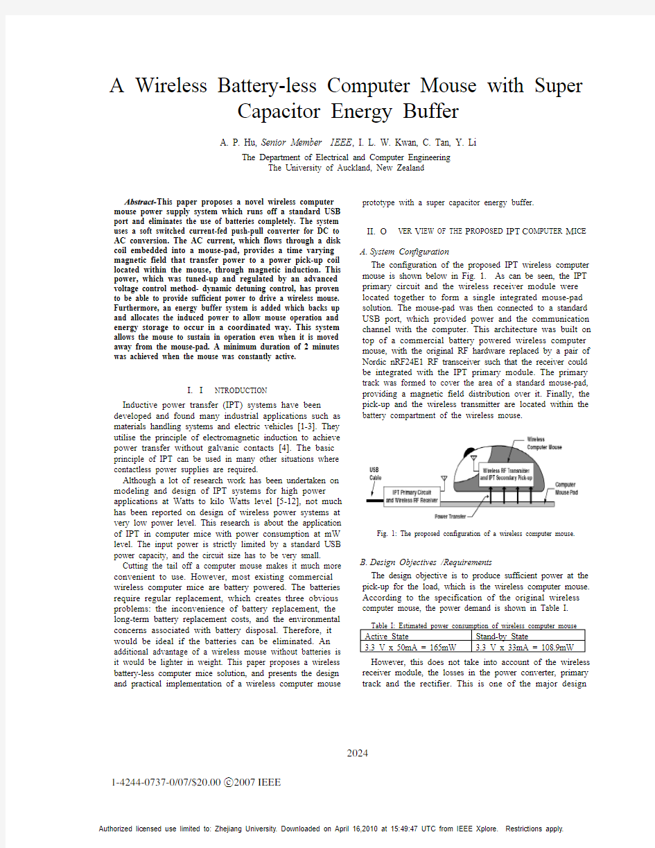
The configuration of the proposed IPT wireless computer mouse is shown below in Fig. 1. As can be seen, the IPT primary circuit and the wireless receiver module were located together to form a single integrated mouse-pad solution. The mouse-pad was then connected to a standard USB port, which provided power and the communication channel with the computer. This architecture was built on top of a commercial battery powered wireless computer mouse, with the original RF hardware replaced by a pair of Nordic nRF24E1 RF transceiver such that the receiver could be integrated with the IPT primary module. The primary track was formed to cover the area of a standard mouse-pad, providing a magnetic field distribution over it. Finally, the pick-up and the wireless transmitter are located within the
battery compartment of the wireless mouse.
Fig. 1: The proposed configuration of a wireless computer mouse.
B.Design Objectives /Requirements
The design objective is to produce sufficient power at the pick-up for the load, which is the wireless computer mouse. According to the specification of the original wireless computer mouse, the power demand is shown in Table I.
Table I: Estimated power consumption of wireless computer mouse Active State Stand-by State
3.3 V x 50mA = 165mW 3.3 V x 33mA = 108.9mW
However, this does not take into account of the wireless receiver module, the losses in the power converter, primary track and the rectifier. This is one of the major design
2024 1-4244-0737-0/07/$20.00c 2007IEEE
challenges, considering the available power of a standard USB is only 100mA for low power mode, and 500mA for high power mode at 5V. To make the system actually work, the power converter for high frequency magnetic field generation, as well as the power pick-up circuit has to be very efficient. With respect to this challenge, the appropriate converter, track material and secondary voltage regulation has been selected and designed. These will be discussed in the preceding section.
Fig. 2: Design Flowchart.
The design and implementation of an IPT system is a complex process involving the juggling of many parameters. The steps as shown in Fig. 2 were adopted to provide a rational flow of the project work.
III. P RIMARY I MPLEMENTATION
A.Resonant Converter
As described in section I, resonant converters are more power efficient due to its ability to achieve ZVS. Traditionally, controllers and zero point detectors were required to:
?Assist the set-up of the oscillation.
?Control the commutation of the switches on the two branches of the resonant converter, such that the
oscillation can be sustained and ZVS achieved.
However, a novel self-sustained current-fed push-pull resonant converter with no additional controllers [4] has been developed for this project. This largely reduced the complexity, power budget stress and the over all cost of the system. The structure of the current-fed push-pull resonant
converter is shown in Fig. 3.
Fig. 3: The self-sustained current-fed push-pull resonant converter.
As can be seen, the circuit comprises a current-fed push-
pull inverter with parallel compensation. The exception is that each switch obtains its switch driving signal form the input of the alternative switch. Since the switching is fully controlled by the resonance, the switching instances will occur at the zero crossing and ZVS is achieved. Since the direction of the current is reversed when the switches exchange its on-off state, the current is also in phase with the voltage. This means zero phase angle (ZPA) operation is also achieved, hence only real power P is delivered to the resonant tank.
Self-starting and ZVS cannot be achieved if the primary quality factor is below a critical value. The primary quality factor is defined as:
P
P
P R
L
Q0
ω
=(1)
Where ?0is the nominal (oscillating) frequency, L P is the primary track inductance and R P is the track resistance. According to [13] and [14], the minimum Q P for self-starting
and ZVS is 2.54 and 1.86 respectively.
The current-fed push-pull resonant converter was constructed, and tested. It was able to start up and shut down automatically without any problem. The resultant voltage waveforms are shown in Fig. 4. It c an be seen c learly that
the voltage a c ross one swit c h rises smoothly from zero voltage after the voltage a c ross the other swit c h rea c hes zero. The final resonant voltage a c ross the tuning c apa c itor
is an ex c ellent sinusoidal voltage sour c e, whi c h is used to drive the tra c k loop.
B.Primary Track Configuration
The physical configuration of the primary track determines the distribution of the magnetic field, which has a great effect on the power transfer efficiency. Equation 2 below describes the relationship between V OC, magnetic
2007Second IEEE Conference on Industrial Electronics and Applications2025
field strength and distribution:
⊥=B OC NBA V 0ω (2)
.
Fig. 4: Voltage waveforms over switches (1&2) and tuning capacitor (3)
Where N is the number of turns of the pick-up coil, A is the area enclosed by the pick-up coil and B is the magnetic flux density component that cuts perpendicularly through A. From this equation it can be seen the primary track configuration should have a field distribution such that it is cutting perpendicular through the area enclosed by the pick-up, at any location on the mouse-pad.
Two configurations, the spiral and the disk coil configuration, have been considered. The analysis of each is
shown below:
Fig. 5: The spiral coil configuration.
For the spiral configuration, the flux in the vertical
direction is cancelled out by neighboring wires.
Consequently, the magnetic field flows within the horizontal plane, or, along the surface of the mouse-pad. The flow
direction in the horizontal plane is shown by the arrows
below in Fig.5 (a).
With this field orientation, the pick-up will have to be
rotated on different parts of the spiral coil to achieve maximum power transfer, as shown in Fig.6 (b). Another
possibility is to use two pick-ups. However, both of these
options are not practical considering the limited space
available in a wireless-mouse.
Fig. 6: The magnetic field distribution of a spiral coil distribution.
Fig. 7: The disk coil configuration.
In contrast, a disk coil configuration, as shown in Fig.7, has a simpler magnetic field distribution, as shown in Fig.8. By having the enclosed plane of the pick-up perpendicular to the vertical axis, the angle between the pick-up and the field direction would be more optimal on different parts of a disk
coil. Hence the disk coil was adopted.
Fig. 8: The magnetic field distribution of the disk coil configuration.
Multi-strands Litz wires were used to form the primary track, as it has a lower AC resistance which helps to reduce the AC power losses. After practical experiments, it has been
found that the maximum power requirement of 165mW has
been met in most locations on the mouse pad.
IV. S ECONDARY P ICK -UP I MPLEMENTATION
So far, most blocks of the IPT system have been implemented. However, it has been found at certain locations the open circuit voltage V OC was lower than the
requirement of 3.3 volts. As discussed in section II-B, parallel pick-up compensation can increase V OC by a factor of Q S .Hence parallel tuning was adopted. However, this
introduced another problem: a parallel compensated pick-up behaves like a current source and the supplied voltage
20262007Second IEEE Conference on Industrial Electronics and Applications
changes with the load. There is a potential danger of the tuned voltage exceeding the maximum voltage of 3.6 volts. For this reason, DDC (dynamic detuning control), a smart voltage regulation method has been developed to regulate the output voltage to be constant. A.
Principle of DDC
Fig. 9: The DDC circuit diagram.
A simplified DDC circuit is shown below in Fig. 9. In this circuit C t is the detuning capacitor and C f is a voltage stabilising capacitor. When the load voltage V L exceed a limit threshold, the capacitor switching control circuit switches on S, which completes the connection of C t ,changing the over-all tuning capacitance to (C S +C t ). This changes the amount of tuned-pickup current output, and hence V L .
There are two possible tuning schemes: under-tuning and over-tuning. In under-tuning the combined value of C t and C S is equal to the resonance capacitance, which gives the maximum tuned pick-up output current as shown in Fig.10. In this application, this maximum point should provide a V L of 3.3 volts. For over-tuning C S is set to the resonance capacitance, while C t is set such that (C S +C t ) will reduce the tuned pick-up output current to an appropriate level. In a nutshell, the under-tuning scheme attempts to switch on more frequently to provide the power needed under heavy loads, where as the over-tuning scheme switches on when
there is excess power.
Fig. 10: Relationship between tuning capacitance and parallel
compensated pick-up output current.
This control mechanism is much more efficient than Zener diodes or linear regulators, in which unused power is
dissipated as heat. This disadvantage is not present in DDC, as it regulated by detuning the power pick-up.
B.Performance of the DDC circuit
The performance of the DDC circuit was tested with both the tuning schemes. It was discovered for this application the under tuning scheme produced less power (140mW), as the DDC circuit was constantly switching to provide sufficient power to the load, and power was lost in this constant switching process. In contrast, the over-tuning scheme switched only when there was excess power. Consequently the switching loss was much smaller and a power output of 193mW was obtained.
The waveform of V L ,which is the voltage across the wireless computer mouse input,and the switching signals for the over-tuning scheme is shown below in Fig. 11. It can be seen that V L
was successfully controlled at about 3.3V.
Fig. 11: V L and switching signal with over-tuning DDC.
V. P ROTOTYPE P ERFORMANCE
The developed prototype circuit was tested with a standard USB power supply. It has found that the IPT power supply can successfully delivered the required power at all locations within the disk coil.
Finally the total power consumed from the USB power supply is recorded in Table II. It can be seen that the maximum power consumption under active state was within the low-power mode limit of the USB. Hence, it was concluded a successful prototype capable of supplying the required power from a USB power supply was achieved.
Table II: Power consumed from the USB power supply. VI. E NERGY B UFFER S YSTEM
An intrinsic limitation of the IPT technology is the limited power transfer range between the primary and the pick-up. Consequently, the movement of the IPT wireless computer mouse was limited within the mouse-pad. This would be
Operating Condition
Current Drawn
(mA)
Power Consumption
(mW)
Active State 96 480 Stand-by State 85 425 Mouse away from pad
57
285
2007Second IEEE Conference on Industrial Electronics and Applications 2027
inconvenient in situations where the mouse is required to move away from the mouse-pad, for examples, when it is used for power point presentations or computer gaming. This
intrinsic disadvantage however, could be remedied by installing an energy buffer in the mouse.
The objective of the energy-buffer is to reserve excess
energy to sustain computer mouse operation when the power
supply is not available. The following design objectives were
set:
?The buffer must be charged relatively quickly, and
provide enough power for a suitable duration. In other
words, the energy buffer must have high power
density and suitable energy density. The suitable
candidate identified was super capacitors, which have
a very high power density and superior energy density
compared to the traditional capacitors.
?The charging of the energy buffer must have minimum interference to mouse operation. In other
words, a suitable power management circuit must be
implemented to distribute the power between the buffer and the mouse.
?The power transfer capability of the IPT system must be boosted such that enough power would be available to support buffer charging and mouse operation.The super capacitor was selected based on its capacitance to provide a suitable balance between the required charge time and sustain duration, so as to achieve a smooth operation. The IPT system was enhanced by increasing the operating frequency, improving the primary track configuration to provide a stronger magnetic field. The required V OC was increased to 10 volts to supply the super capacitors, in order to provide a larger discharge profile. Consequently a 3.0 volt step-down regulator was used before the load.
A.Power Management Circuit
Fig. 13 illustrates the DC part of the secondary circuit after the pick-up tuning. The energy buffer is highlighted in
orange, and the power management circuit in yellow.
Fig. 12: Circuit diagram showing the power management circuit and the energy
buffer in the secondary circuit.
The power management circuit is consisted of a simple comparator and BJT switch. When power is induced in the pick-up, the temporary capacitor and the load is supplied
first. When the voltage across the temporary capacitor (V Ctemp ) reaches a certain threshold, the comparator circuit
will drive the BJT on, completing the energy buffer’s connection and enable charging. During this time the load is
momentarily supplied by the temporary capacitor. The charging of the energy buffer stops as soon as V Ctemp drops below the threshold. This cycle repeats until the energy buffer becomes fully charged. As such, the power is appropriately distributed between the energy buffer and the computer mouse. B.Result
It has been discovered that the enhanced IPT system produced sufficient power to handle both the real time mouse operation and the energy buffer storage. After the temporary capacitor was charged to the preset threshold, sufficient power was still available to charge the energy
buffer capacitors and at the same time allow mouse operation. However, if both C temp and the energy buffer were charged simultaneously, it would take a very long duration
for V L to reach 3.3 volts. Hence it was concluded the power management circuit was successful in distributing the
induced power between the mouse and the energy buffer appropriately. Fig. 13 shows V L (top waveform) has been kept constantly at 3.3 volts, while the energy buffer is
steadily charged (bottom waveform).
Fig. 13: Waveform showing simultaneous charging of energy buffer and mouse
operation.
Finally, the integrated IPT and energy buffer system was tested on a commercial wireless mouse (originally battery powered). When the final prototype was placed on the mouse-pad location with the strongest field strength, it took 0.96 seconds for V L to reach to 3.0 volts, and 21 seconds to charge both C temp (1Farad) and the energy buffer (1Farad) fully. When fully charged, the mouse could be sustained for 2 minutes under constant active-state and 9 minutes under constant stand-by state. This would be very useful for short duration off-pad operation of the mouse, such as the situation in computer gaming.
20282007Second IEEE Conference on Industrial Electronics and Applications
VII. C ONCLUSION
This paper has proposed a complete wireless/battery-less
IPT computer mouse solution. A working prototype driven
by a standard USB power source have been successfully
designed and tested. The self-sustained current-fed push-pull
resonant converter and the DDC (Dynamic Detuning
Control) circuit were proven to be simple but very effective.
Furthermore, an energy buffer system has been developed
for a minimum 2 minutes off-pad option, which further
enhanced the usability of the proposed mouse system.
R EFERENCES
[1]Green, A.W and Boys, J.T.:‘‘10kHZ indu c tively c oupled power transfer
c on c ept an
d c ontrol, Fi ft h I nt er nat io nal Co nf er
e n ce o n Power
El ec t ro n ic s an d V a ri a b l e-S p eed Drive s, 1994. pp 694-699.
[2]Hu, A.P., Chen, Z.J.; Hussmann, S., Govi c, G.A.; Boys, J.T.: ‘‘A
dynami c ally on off c ontrolled resonant c onverter designed for
c oalmining battery c harging appli c ations’’, Proceedi n g s o f 2002.
I nt er nat io nal Co nf ere n ce o n Power Sy st em Tech n o l ogy, vol. 2, pp.
1039-1044. O c t 2002.
[3]Stielau, O.H., Boys, J.T., Covi c, G.A. and Elliot, C.G.: ‘‘Battery
c harging using loosely c ouple
d indu c tiv
e power transfer’’, 8t h Eu ro p e an
co nf ere n ce o n p ower e l ec t ro n ic s an d appl ic at io ns, EPE,99, pp. 7-9. Sept
1999.
[4]Hu, A.P.: ‘‘Sele c ted resonant c onverters for IPT power supplies’’, PhD
thesis,Department of Ele c tri c al and Computer Engineering, University
of Au c kland, O c t 2001.
[5]Yungtaek Jang, M. M. Jovanovi c.: ‘‘A c onta c t-less ele c tri c al energy
transmission system for portable-telephone battery c hargers’’, I EEE
Tr ansa c t io ns o n I n d ust ri al El ec t ro n ic s, vol. 50, pp 520-527. Jun 2003.
[6]J. T. Boys, G. A. Covi c, Yongxiang Xu, ‘‘DC analysis te c hnique for
indu c tive power transfer pi c k-ups’’, I EEE Power El ec t ro n ic s Le tt er s,
vol. 1, pp. 51-53, Jun 2003.
[7]Abe, H.; Sakamoto, H.; Harada, K.: ‘‘A non-c onta c t c harger using a
resonant c onverter with parallel c apa c itor of the se c ondary c oil’’,I EEE
Tr ansa c t io ns o n I n d ust ry A ppl ic at io ns, vol. 36, pp. 444-451. Mar-Apr
2000.
[8]Kelley, A.W.; Owens, W.R.: ‘‘Conne c tor-less power supply for an
air c raft passenger entertainment system’’, I EEE Tr ansa c t io ns o n Power
El ec t ro n ic s, vol.4, pp. 348-354. Jul 1989.
[9]Elliot, G.A.J., Boys, J.T., Covi c, G.A.: ‘‘A design methodology for flat
pi c k-up ICPT systems’’, pap er su bmi tt ed an d a cce pt ed f or IP E C
I nt er nat io nal Co nf ere n ce,2006.
[10]Boys, J.T., Covi c, G.A. and Green, A.W.: ‘‘Stability and c ontrol of
indu c tively c oupled power transfer systems’’, I EE Proceedi n g s o n
El ec t ric Power A ppl ic at io ns,vol. 147, pp 37-43, Jan. 2000.
[11]Stielau, O. H., Covi c, G. A.: ‘‘Design of loosely c oupled indu c tive
power transfer systems,’’ I EEE-P E S/I EE/CS EE I nt er nat io nal
Co nf ere n ce o n Power Sy st em Tech n o l ogy, POWERCON 2000, De c
2000.
[12]Wang, Chwei-Sen, Stielau, O.H., Covi c, G.A.: ‘‘Load models and their
appli c ation in the design of loosely c oupled indu c tive power transfer
systems’’, Proceedi n g s o f2000 I EEE I nt er nat io nal Co nf ere n ce o n
Power Sy st em Tech n o l ogy, Vol. 2, pp.1053-1058, De c ember 2000.
[13]Boys, J.T., Hu, A.P., Covi c, G.A.: ‘‘Criti c al Q analysis of a c urrent-fed
resonant c onverter for ICPT appli c ations’’, I EEE El ec t ro n ic s Le tt er s,
vol. 36, pp1440-1442. Aug. 2000.
[14]Hu, A., Boys, J.T., Covic, G.A.: ”Dynamic ZVS direct on-line start up of
c urrent fe
d resonant converter using initially forced DC current”,
Proceedi n g s o f t he 2000 I EEE I nt er nat io nal Sym p o s i u m o n I n d ust ri al
Electronics, vol.1, pp. 312 – 317. Dec 2000.
2007Second IEEE Conference on Industrial Electronics and Applications2029
汉德翻译材料 翻译地名的汉译德处理
地名的汉译德处理 1. 翻译的方法与地名翻译 翻译是用一种语言(译语)的文本来替换另一种语言(原语)的文本的过程,即语言符号转换的过程。在这个过程中,原语的符号被转换成相应的译语的符号,并为操译语的人所理解。为了达到这样一个目的,在翻译过程中就应注意等值的问题。严复所提出的“信达雅”的翻译标准,其中“信”就是指翻译的等值性,即译文正确表达原文中的信息。因此,翻译实践的中心问题就是寻找译语的等值成分。根据翻译过程中所追寻的等值的不同层次与级别,可以将其归入不同的类型。以下例举常用的几种翻译类型: 语音翻译:是译文和原文在语音上等值的译法。跟据音译的规则以译语的书写记录方法来记录原语的读音。译文力求保持原文的读音,但在字型上则保留译语的特点和习惯。例如将法语单词 bureau 译成德语的Büro。在汉语中也有许多这样经语音翻译而得的词,如咖啡、沙发、坦克等。 字型翻译:是按字型学原理,译文与原文在字型上等值的译法。对于使用相同字母书写系统的语言而言,其相互间的字型翻译究其根本就是转写的过程。其实,这样的字型翻译就是译语使用源自于原语的借词的过程。例如英语中的 computer 一词在德语中仍写为 Computer。汉语和西方拼音语言之间字型翻译极为罕见,原因即在于文字之间差异太大。(当前有些汉语的专业文献中在引用人名或一些专业术语时,往往直接以字母拼写而不用汉字。但这只是权宜之计,未经汉化,不用汉字来书写,这些词是永远进入不了汉语的。) 以上两种译法,是以原文的读音为基础和出发点的(字母本身也是一种表达一定发音的符号),等值性在词汇层次上的翻译方法,因此一般亦可概括称为音译。 与音译不同,有些译法不考虑原文的读音,而以其所表达的意义为基础和出发点追求译文的等值性,故通常称为意译。主要有以下几种类型: 逐字翻译:顾名思义,是以单个词汇为单位追求等值的译法,可以理解为词汇层次上的意译。 直译:始于逐字翻译,在词汇上保持等值,但在语法结构商也追求同原文的对应。其等值性可位于单词和词组的层次上。 语义翻译:是追求译文全文与原文全文在所表达的意思上等值的译法,也是日常工作中应用最广的译法。除了字、词、句等语言单位要求等值,语义翻译通常还需考虑不同的语境关系,以期达到在篇章层次上的等值。 以上所列举的三种意译的方法,其差异可通过下面这个例子来说明: 英语原文:It’s raining cats and dogs. (下着倾盆大雨。) 德语译文:Es ist regnend Katzen und Hunden. (逐字翻译) Es regnet Katzen und Hunden. (直译) Es regnet in Str?men. (语义翻译) 从上面的例子可以看出,语义翻译是等值层次最高,难度最大的译法。通常翻译中一般都采用语义翻译。但对地名翻译而言,由于原文本身就是单个单词或词组,等值性也仅限于此,所以语义翻译反而较为罕见,而以音译,以及意译中的逐字翻译和直译。一般说来,在西欧语言(英、法、德、西、葡等拼音语言)之间的地名互译比较简单,以字型翻译为主。这是因为这些语言都使用相同的字母系统(拉丁字母),在字母这个层次上符号是通用的。所以一门语言可以不加改动(或只做很小改动)地使用另一门语言的一些词。譬如法国首都巴黎,在法语、英语和德语中都为Paris,尽管发音有所不同,但在字型上是完全一致的。有时,这种字型翻译的过程中需要对原词做少许改动,通常这样的改动是以符合译语的正字法规则为目的的。例如伦敦这个词,英语中为London,德语译词采用了转写不误的办法,但到了法语中则须写成Londres。不仅是城市的名字,有些景点的名称在西方语言中也是可以这样借用的。例如著名的巴黎圣母院,法语中为 Notre Dame,英语、德语都可以直接借用。前面说过,西方语言之间之所以能这样互译,是因为它们有着相同的字母(书写)系统和相似的读音规则。作为表意语言的汉语,在书写上和发音上都于西方语言有着显著的区别,因此在翻译地名时,一般不能采用字型翻译,而要灵活运用各种不同的方法,找出最确切的译名来。
火车站特等站和一等站名单
全国一级站--绵阳站 [编辑本段]简介 ①一等站是全国铁路车站等级中的一种. 具备下列三项条件之一者为一等站: (1)日均上下车及换乘旅客在15000人以上,并办理到发、中转行包在1500件以上的客运站。 (2)日均装卸车在350辆以上的货运站。 (3)日均办理有调作业车在3000辆以上的编组站。 具备下列三项条件中两项者为一等站: (1)日均上下车及换乘旅客在8000人以上,并办理到发、中转行包在500件以上。 (2)日均装卸车在200辆以上。 (3)日均办理有调作业车的2000辆以上。 ②一等站,又称为头等站是台湾铁路管理局(台铁)的车站级别。依照台铁文献的定义,一等站为依照车站业务情形,按台铁评分标准在55分以上、90分以下,并经抄陈主管机关备查者。所谓「业务情形」包含了营运进款、客运业务、货运业务、运转及行车等因素。[编辑本段]全国特等站和一等站名单 1、全国铁路特等站 1 丰台西站特等编组站北京铁路局; 2 北京站特等客运,北京铁路局; 3丰台站特等客、货运,北京铁路局; 4 天津站特等客、货运北京铁路局; 5 北京西站特等客运北京铁路局; 6 石家庄站特等客、货北京铁路局; 7郑州北站特等编组站郑州铁路局; 8郑州站,特等客、货运郑州铁路局; 9 郑州东站特等货运郑州铁路局; 10江岸西站特等货运武汉铁路局; 11 武昌站,特等客、货运武汉铁路局; 12 西安站,特等客、货运西安铁路局; 13西安西站特等货运,西安铁路局 14株洲北站特等编组站广州铁路集团公司 15株洲站特等客、货运广州铁路集团公司 16衡阳北站特等货运;广州铁路集团公司 17衡阳站,等客、货运广州铁路集团公司 18广州北站特等编组站广州铁路集团公司 19广州站,特等客、货运广州铁路集团公 20广州南站特等货运广州铁路集团公司 21哈尔滨站特等客、货哈尔滨铁路局; 22佳木斯站特等客、货哈尔滨铁路局; 23牡丹江站特等客、货哈尔滨铁路局; 24齐齐哈尔特等客、哈尔滨铁路局 25山海关站特等客、货沈阳铁路局;
厦门枋湖长途汽车客运中心调研报告
厦门枋湖长途汽车客运中心调研报告 目录 一.调查的对象 二.汽车客运站概念 三.项目概况 四.总平面 五.平面流线分析 1.候车厅 2.售票厅 3.其他交通 六.总结
一.调查对象 调研地点:枋湖长途汽车客运中心 调研时间:2014.4.23 摘要:通过对枋湖客运中心的调研,大致了解汽车客运站的布局流线,吸取其优点,同时发现不足之处以便加以改进。同时查阅大量资料对车站有个框架性的了解,对于一些硬性指标有大体上的把握,接下来对要设计的车站要有自己的设计理念。 二.汽车客运站概念 专门办理旅客运输业务的汽车站,一般设在公路旅客集散点,其规模大小视当地的客运量而定。中国把汽车客运站分为三等。省辖市及港口、铁路枢纽一般设一等站;县、市人民政府驻地一般设二等站;乡政府驻地或较大集镇设三等站。客运站的主要工作分商务和车务两大部分。商务如售票、接受行李包裹的托运等;车务如车辆的调度、检查、加油、维修、接收和发送等。客运站的组织机构和人员配备视其等级和业务繁简而定,通常设有售票处、问事处、行包托运处、小件寄存处、候车室、停车场等。大的客运站还有为旅客和车辆驾乘人员提供食宿的设施。 三.项目概况 枋湖客运中心集长途客运、公交枢纽、出租 车服务、商业卖场等四大功能于一体,是厦门岛 内最大的长途客运综合枢纽站。客运中心与成功 大道有专用匝道,经厦门大桥或杏林大桥、集美 大桥离开厦门岛, 不仅省去大车在岛 内“乱转”引起的 交通资源紧张,也能避免非法揽客。到了发车时间, 旅客需要乘坐自动扶梯,下到1层的发车区。发车区拥有36个发车位,27个检票口,能快速引导旅客上车。 四.总平面
拼音
拼音:(xià mén) 英译:Xiamen(旧译Amoy) 区号:0592 邮政编码:361000 厦门(xiàmén)市是中华人民共和国15个副省级城市之一,五个计划单列市之一,享有省级经济管理权限并拥有地方立法权;既是中国最早实行对外开放政策的四个经济特区之一,又是十个国家综合配套改革试验区之一(即“新特区”);东南沿海重要的中心城市,现代化国际性港口风景旅游城市;《中华人民共和国国民经济和社会发展第十二个五年规划纲要》及国务院批复的《厦门市深化两岸交流合作综合配套改革试验总体方案》明确提出加快推进两岸区域性金融服务中心,东南国际航运中心,大陆对台贸易中心(两岸新兴产业和现代服务业合作示范区)建设。 厦门下辖思明、湖里、集美、海沧、同安、翔安六个行政区。其中,思明区,湖里区在厦门岛内,厦门岛又名鹭岛,宋曰嘉禾屿,明曰中左所。美国总统尼克松曾称赞厦门“东方夏威夷”。这里地处亚热带,全年气候宜人,风景秀丽,环境整洁,拥有“国际花园城市”、“国家卫生城市”、“国家园林城市”、“国家环保模范城市”、“中国优秀旅游城市”和“全国十佳人居城市”、“联合国人居奖”、“全国文明城市”等殊荣誉。在《经济日报》2002年初发布的“中国城市综合竞争力排行榜”中,厦门名列第五。 2013年,厦门参与由中国国际广播电台国际在线推出的2013中国城市榜评选活动,将角逐“最中国生态名城”名号。 编辑本段地理位置 厦门位于福建东南部,闽南地区。 厦门市位于东经118°04?04?、北纬24°26?46?,地处我国东南沿海----福建省东南部、九龙江入海处,背靠漳州、泉州平原,濒临台湾海峡,面对金门诸岛,与台湾宝岛和澎湖列岛隔海相望。厦门由厦门岛、鼓浪屿、内陆九龙江北岸的沿海部分地区以及同安等组成,陆地面积1575.16多平方公里,海域面积300多平方公里。是一个国际性海港风景城市。分为思明区、湖里区、翔安区、同安区、集美区、海沧区六个行政区。其中,思明区、湖里区在厦门岛内。 编辑本段自然气候
英语介绍厦门
noodle with satay sause(沙茶面),Xiamen style jelly seaworm(土笋冻),fish ball(鱼丸),zongzi或traditional chinese rice-pudding with meat(肉粽) 美丽厦门之英文介绍大全集 01: 厦门英文介绍About Xiamen 02: 厦门八大景八小景tour xiamen 03: 鼓浪屿英文介绍1 GULANGYU ISLAND 04: 鼓浪屿英文介绍2 GULANGYU ISLAND 05: 厦门市市鸟白鹭City Bird-Egrets 06: 厦门市市花三角梅英文介绍City Flower-Bougainvillea glabra 07: 厦门南普陀英文介绍Nanputuo Temple 08: 集美旅游景点英文介绍Jimei Tourist Area 09: 同安旅游景点英文介绍Tong’ an Tourist Area 10: 厦门中秋节英文介绍Mid-autumn Festival 11: 厦门划龙舟英文介绍Dragon boat festival 12: 厦门博饼英文介绍Mooncake gambling 13: 厦门歌仔戏英文介绍Gezai Opera 14: 元宵节英文介绍The Lantern Festival 15: 闽南功夫茶英文介绍Gongfu Tea About Xiamen厦门英文介绍 Xiamen is an island city with a rich and dramatic history, replete with pirates, rebel leaders, and European merchants. Now linked to mainland Fujian by a causeway, Xiamen retains a strong international flavor. Known in the West as Amoy, Xiamen has a long history as a port city, and later became a center of British trade in the 19th century. Their foreign settlements, later taken over by Japanese invaders at the start of World War II, were established on the nearby small Gulangyu Island. Many of the old treaty-port and colonial buildings in Western styles survive. Xiamen was declared one of China’s first Special Economic Zones in the early 1980’s, taking advantage of the city’s heritage as a
厦门火车站轨道预留工程折返线区间隧道施工监测方案
. 厦门火车站轨道交通土建预留工程 折返线区间隧道施工监测方案 编制: 审核: 审批: 福建福大建筑设计有限公司 2014年10月31日
目录 1.工程概况 (1) 1.1区间项目概况 (1) 1.2工程地质条件 (2) 1.3水文地质概况及地质构造、地震烈度 (4) 1.4区间隧道与厦门火车站位置关系 (5) 2.监测目的 (8) 3.监测依据 (8) 4.监控量测方案设计原则 (9) 5.施工监测项目及监测频率 (10) 5.1监控量测内容及监测频率 (10) 5.2监测周期 (11) 6.监测项目、监测方法和数据处理 (12) 6.1监测控制网布设 (12) 6.2施工监测点布置原则 (13) 6.3洞内洞外观察 (14) 6.4地表沉降监测 (14) 6.5隧道拱顶沉降监测 (15) 6.6隧道净空收敛监测 (15) 6.7邻近建筑物、轨道位移监测 (16) 6.8地层位移监测 (17) 6.9围岩压力及断面两层支护间压力 (18) 6.10衬砌格栅应力及二衬钢筋应力监测 (18) 6.11锚杆轴力监测 (18) 6.12隧道底部隆起量测 (19) 6.13围岩弹性波测试 (19) 6.14爆破振速监测 (20) 6.16监测点的保护和补救 (21) 7.监测人员及主要仪器设备 (21)
7.1监测人员 (21) 7.2主要仪器设备 (21) 8.监测报警值 (22) 9.监测应急措施 (24) 10.监测资料的处理 (25) 11.工序管理及监测信息反馈制度 (25) 12.监控量测质量保证措施 (27) 13.附件 (28)
1.工程概况 1.1区间项目概况 折返线区间为起点~厦门火车站站,起点设计里程为DK0+193.273,终点里程为左DK0+549.001,全长355.728双线延长米。 本区间隧道左右线均包含一组半径R=1000m曲线,线间距5.0m~7.1m,设置有一组12号5.0m线间距交叉渡线。 区间隧道正穿厦门火车站,至下穿厦门火车站北广场外改移道路起,下穿南北广场地下空间、厦门火车站站房、站台出道地道及轨道,从厦门火车站旅客地道正下方通过,轨道交通轴线与旅客地道轴线投影重合。区间隧道拱顶距厦门火车站底板结构距离为9.0~10.0m;隧道左右两侧分布有车站结构桩基,其中1处隧道结构与桩基最小净距为 2.6m,有4处与桩端净距为2.6~5m,其余段与桩基净距为5~10m。根据线间距和所衔接的车站型式,采用单洞双线断面,矿山法暗挖施工。 图1-1总平面布置图 区间范围内现状地面标高5.8m~19m,折返线区间至起点以2‰单向坡进入厦门火车站站,轨面标高为-11.883m~-11.170m,区间隧道最大埋深30.8m,最小埋深16m。区间主要穿越地层为中风化花岗岩,下穿北广场落客平台区段通过地层依次为全风化花岗岩、散体状及碎裂状强风化花岗岩,局部夹辉绿岩岩脉。其中Ⅲ级围岩16.73m,Ⅳ级围岩43m,Ⅴ级围岩297m。
散文厦门
散文厦门 篇一:一篇关于厦门的文章 General Information: Xiamen, also known as Amoy, is one of China's most attractive cities. Situated at the coast of the Fujian Strait this wonderful city with its palm trees, vast beaches and historical architecture attracts many people. Xiamen and the surrounding southern Fujian countryside are the ancestral home to large communities of overseas Chinese in Southeast Asia and Taiwan. The city was a treaty port in the 19th century and one of the four original Special Economic Zones opened to foreign investment and trade when China began economic reforms in the early 1980s.Today, Xiamen is known in China as a prosperous and clean city with a pleasant subtropical seaside climate. It is endowed with educational and cultural institutions supported by the overseas Chinese diaspora. In 2019, Xiamen was ranked as China's second most suitable city for living.The sign of Xiamen is royal poinciana, bougainvillea and egret. The official language of all government business is Mandarin and the local vernacular is Amoy, a dialect of Southern Min, also called Hokkien. Amoy is widely used and understood across the southern region of Fujian province as well as overseas. Tourism- Gulangyu
厦门火车站世贸商城调研报告
竭诚为您提供优质文档/双击可除厦门火车站世贸商城调研报告 篇一:厦门火车站世贸商圈调研报告 一、火车站世贸商圈介绍及商圈概况火车站世贸商圈地处厦禾路中段,是厦禾路大型繁华商业路段(厦门核心商业区)与厦禾路生活区路段(厦门时尚都市高档住宅典范区)的分界点,拥有厦门火车站、公交总站、汽车站的三大交通枢纽的人流,目前已开业有世贸商城、嘉年名华、华联百货等,建设中有罗宾森广场、火车站地下商业街等。突出年轻、时尚的主题商业定位。从商业到市政配套,从住宅品质到都市生活观念都代表了这座城市最高水平。火车站世贸商圈 ◆商业辐射:以火车站、公交总站、梧村汽车站的流动人流为依托,目前日商业人流25万人次。 ◆功能描述:城市中心型商业,主题明显,时尚型商业。 ◆商业规模:共有22万m2,世贸商城5万m2、嘉年名华2万m2、罗宾森广场7万m2,香格里拉3万m2,以及梧村汽车站、火车站地下商业街等5万m2。 ◆业态分布:以巴黎春天百货、沃尔玛等主力店为依托,
结合肯德基、麦当劳、电影院等 次主力店;未来将通过地下商业步行街与嘉年名华、华联百货、罗宾森广场等联成一体。◆价格表现:销售价格1.5-3.5万元/m2,租金120-400元/m2/月。 ◆商业意义:走时尚主题性商业路线,打造地上、地下联体商业,规划地下商业街连接贯通整个火车站商圈,突破交通因素制约。世贸商城、罗宾森广场、华联百货、嘉年名华等几大商城、商场以及火车站、长途汽车站、公交车站连成一片,串起的周边商业面积可达22万平方米,世贸商城5万㎡、嘉年名华2万㎡、罗宾森广场7万㎡,香格里拉3万㎡,以及梧村汽车站、火车站地下商业街等5万㎡。形成一个四通八达的名副其实的独特大商圈,商圈核心人口达25万。同时,明发商业圈的建设完成与火车站商业圈形成一条其影响整个海西板块的大型商业街。近两年火车站商圈的建设即将发展到更高阶段,长420m,宽38m的地下商业街将火车站区域的世贸商城,罗宾森广场,梧村汽车站商业城等大规模、高档次的商业连接成为一个整体,这样不仅将原各自为营的商业归于一统,形成整合力,扩大影响力,更是解决了未来火车站商圈的交通、停车问题,也进一步改善市政面貌。二商圈业态构成火车站世贸商圈以巴黎春天百货、沃尔玛等主力店为依托,结合KFc、麦当劳、电影院等次主力店;未来将通过地下商业步行街与嘉年名华、华联百货、罗宾森
中国地名英文新旧拼法对比
中国地名英文新旧拼法比照(邮政式拼音、汉语拼音) 邮政式拼音地名汉语拼音 Mukden 沈阳Shenyang Peking 北京Beijing Nanking 南京Nanjing Sian 西安Xi'an Canton 广州Guangzhou Amoy 厦门Xiamen Tsingtao 青岛Qingdao Dairen/Taline/Dalny 大连Dalian Namhoi 南海Naihai Seundak 顺德Shunde Chu-hai 珠海Zhuhai Shekki/Chung-shan 中山Zhongshan Port Arthur/Ryojun 旅顺Lüshun/Lüshunkou Chengtu 成都Chengdu Tientsin 天津Tianjin Foochow/Fuchow 福州Fuzhou Y enan 延安Y an'an Soochow/Wuxian 苏州(吴县)Suzhou Wusih/Wuhsi 无锡Wuxi Suchow 徐州Xuzhou Chungking 重庆Chongqing Tsinan 济南Jinan Chefoo 烟台Y antai Kirin/Chilin 吉林Jilin Kweilin 桂林Guilin Kukong 韶关Shaoguan Swatow 汕头Shantou Teochew/Chiu Chow 潮州Chaozhou Chinchew/Chinchu 泉州Quanzhou Changchow 漳州Zhangzhou Chankiang/Chan-chiang 湛江Zhanjiang Hanchung 汉中Hanzhong Sining/Hsi-ning 西宁Xining Kongmoon 江门Jiangmen Hangchow/Hangchou 杭州Hangzhou
厦门英文介绍
美丽厦门之英文介绍大全集(一) 01: 厦门英文介绍About Xiamen 02: 厦门八大景八小景Tour Xamen 03: 鼓浪屿英文介绍1 Gulangyu Island 04: 鼓浪屿英文介绍2 Gulangyu Island 05: 厦门市市鸟白鹭City Bird-Egrets 06: 厦门市市花三角梅英文介绍City Flower-Bougainvillea glabra 07: 厦门南普陀英文介绍Nanputuo Temple 08: 集美旅游景点英文介绍Jimei Tourist Area 09: 同安旅游景点英文介绍Tong’an Tourist Area 01.About Xiamen厦门英文介绍 Xiamen is an island city with a rich and dramatic history, replete with pirates, rebel leaders, and European merchants. Now linked to mainland Fujian by a causeway, Xiamen retains a strong international flavor. Known in the West as Amoy, Xiamen has a long history as a port city, and later became a center of British trade in the 19th century. Their foreign settlements, later taken over by Japanese invaders at the start of World War II, were established on the nearby small Gulangyu Island. Many of the old treaty-port and colonial buildings in Western styles survive. Xiamen was declared one of China’s first Special Economic Zones in the early 1980’s, taking advantage of the city’s heritage as a trading center and the proximity to Taiwan. Today Xiamen is one of China’s most attractive and best-maintained resort cities. Xiamen was founded in 1394 at the beginning of the Ming dynasty as a center of defense against coastal pirates. Its prosperity was due to its deepwater sheltered harbor, that supplanted nearby Quanzhou, the port that had been the center of the maritime trade with the Indies. In the mid-17th century, Xiamen and Gulangyu Island became a stronghold of Zheng Chenggong, known in the West as Koxinga, a Ming loyalist who held out against the Manchu invaders until being driven to Taiwan. Born in Japan to a Chinese pirate father and a Japanese mother, Zheng became allied with holdout Ming princes in the south who
厦门汽车充电桩项目可行性研究报告
厦门汽车充电桩项目可行性研究报告 规划设计/投资分析/产业运营
报告摘要说明 新能源汽车行业的增长和快速扩张,总伴随着与其密不可分的充电桩 行业的发展。2018年,新能源汽车市场以125.6万辆的销量再创历史新高。2019年上半年,已完成销售61.7万辆,纯电动汽车占比约为80%。预测中 国的新能源汽车销量将达到160万辆。在汽车整体销量下滑的背景下,新 能源汽车的市场表现依然抢眼,补贴退坡也侧面推动了新能源汽车市场竞 争力的走强。新能源汽车保有量的提升是充电服务行业需求端最重要的驱 动力。随着消费者对新能源汽车认可度的提升,充电服务行业也将获得更 大的市场体量和更多样化的发展机会。 充电桩是为各种不同电压等级,各种型号的电动汽车充电的设备。充 电桩运营商类似加油站运营商,充电桩可固定安装墙壁或地面。充电方式 通常提供两种,一种常规充电、一种快速充电。充电时可以计时、计电度 与计金额充电,作为市民为电动车购电的终端。有数据显示,截止2019年底,我国充电桩建设数量超120万个。 该汽车快速充电桩项目计划总投资12961.17万元,其中:固定资 产投资9713.69万元,占项目总投资的74.94%;流动资金3247.48万元,占项目总投资的25.06%。 本期项目达产年营业收入23863.00万元,总成本费用18452.06 万元,税金及附加250.92万元,利润总额5410.94万元,利税总额
6408.20万元,税后净利润4058.20万元,达产年纳税总额2349.99万元;达产年投资利润率41.75%,投资利税率49.44%,投资回报率31.31%,全部投资回收期4.69年,提供就业职位366个。 目前我国的新能源汽车保有量达到100万辆,占全球新能源汽车保有量的50%以上。预计在未来3年,中国新能源汽车仍将保持35%到40%的年增长率。随着新能源汽车与动力电池行业的蓬勃发展,一些投资机构纷纷发力,布局投资充电桩事业,电动汽车充电桩产业也随之迎来大爆发。 充电桩行业是方创资本新能源小组重点关注并持续深耕的行业。作为新能源汽车整车配套必备设施,随着新能源汽车的快速发展以及地方补贴政策逐渐向充电基础设施建设等环节倾斜,充电桩行业即将迎来爆发。
英语中的中文外来词
(一)丝绸——silk 中国是养蚕大国,丝绸的故乡。瓷器和丝绸始终是古代中国对外贸易的绝密技术和看家商品,直到鸦片战争前,英国进口到广州的钢琴,还干不过珠光宝气的丝绸。“silk”的发音,显然是汉语的音译,这个词代表了中国高超的工艺技术和贸易强势。即便现在,丝绸仍在现代生活中充当雍容华丽、典雅高贵的象征。 (二)茶——tea 这个词,又是英国人从拗口的闽南话里偷走的。茶,和丝绸、瓷器比肩,堪称古代中国对外贸易的拳头产品。目前,品茶代表了一种生活方式和文化品位,中国人对人生的思考,几乎都能在袅袅茶烟里找到。据萧乾的《茶在英国》介绍:“茶叶似乎是17世纪初由葡萄牙人最早引到欧洲的……英国的茶叶起初是东印度公司从厦门引进的,17世纪40年代,英人在印度殖民地开始试种茶叶,那时,可能就养成了在茶中加糖的习惯。”据说,即使在“二战”那样物资困乏的时期,法国人定量配给咖啡,英国人则要的是茶,还有一点点糖。茶成了欧洲人的“主心骨”,他们只能跟着茶香如醉如痴地行走,这不是本土的历史与遗传;而是异域文化的征服和同化。18世纪的柴斯特顿勋爵干脆在《训子家书》里写道:“尽管茶来自东方,它毕竟是绅士气味的;而可可则是个痞子、懦夫,一头粗野的猛兽。” (三)世外桃源——Shangrila (Xanadu) 这是两个近意词。都有“世外桃源”的意思。“Shangrila”出自西藏的传说之地——香格里拉,“Xanadu”则是蒙古的元上都。如果要表达“世外桃源”,通常采用“Xanadu”这个词。看来,以出世自居的美国作家梭罗,白白地在瓦尔登湖旁边,做了那么久的“隐士”。讲究“寄情山水、超然物外”的哲学,中国人是当之无愧的开山鼻祖。 (四)风水——Feng Shui 风水,还是音译。它凝聚了古代中国在活人住宅和死人墓地方面的集体智慧。尽管有人打着所谓“科学”的旗号,指斥风水是封建迷信;但是,迷信所谓“科学”,故步自封,则是另外一种迷信。风水的整体原则是“趋利避害”,这也是安全生存最起码的信条。近年来,风水在美国红极一时,从中国人唇齿之间发出的音节,已经成为当代人急需探究的学问。 (五)茶点——dim sum 一听发音,就知道,这个略带小资情调的词儿,来自闽粤。英国人有喝下午茶的习惯,几杯印度红茶,常就一碟甜点。英语原本有表示蛋糕、点心的词,偏偏不用,硬要拽一个来自汉语的生僻字。恐怕多少也有与时尚接轨、和东方同步的优越感吧。中国是茶的故乡,茶点也摇身一变,成为登堂入室的英语外来词。 (六)走狗——running dogs 中国式英语贴切地表达了一种见利忘义、供人驱使的“下三烂”。无从考证,最先运用这个词的是中国人,还是英国人;重要的是,英语世界接纳了“走狗”,并以汉语的思维抚育这个“外来词”。接纳词汇的同时,无形中也接受了中国人的价值观。 (七)纸老虎——paper tiger 这是最令人难忘和扬眉吐气的一个新词。缔造者应该是伟大的民族英雄——毛泽东!他老人家是博学的诗人、雄才大略的政治家、运筹帷幄的军事天才。美国人硬不硬?苏联人牛不牛?原子弹厉害不厉害?……在他眼里,都是色厉内荏的“纸老虎”。只要跟中国人作对,老子就得碰碰硬,看天下“谁主沉浮”。上世纪50 年代的“美帝国主义”、六七十年代的“苏修”,都变成了毛泽东嘲笑的“纸老虎”。这种蔑视强敌、自强不息的精神,当然是中国人对世界文明的贡献。谈笑风声缔造了一个词,足令中国的敌手躲在角落里发抖了。 (八)大款、巨亨——tycoon 这种称呼是近些年才流行街巷的,指有钱有势的商人或者企业家,中国传统的叫法是“大掌柜”。被英语拿走,又是闽粤之地的音译。可见,鸦片战争前,中国商人名声在外,马可·波罗在书里描写的东方,物阜民丰,黄金铺地。来中国走一遭,就像现在某些“假洋鬼子”上趟拉斯维加斯一样。 (九)赌场——Casino 这个词,似乎是地道的西方舶来品,发音“Casino”竟是福建话的音译,可是,为什么英语要拿它表示“赌场”的意思呢?据传,很久以前,移民到美国的福建民工,拿到一点微薄的工资,便在无聊之际,聚众赌博,试试运气。每次开局,都会嚷嚷:“开始了! 开始了!”想不
厦门“24小时汽车救援”暗访调查报告
厦门“24小时汽车救援”暗访调查报告暗访时间: 3月6日21:00-24:00 暗访对象: 我市48家汽车经销商 暗访地点: 湖边水库湖边花园西区观日西路 联动媒体: 厦门晚报《汽车周刊》 青春有限,选择无悔。千里之行始于足下,一切的一切都只是一个开始,关爱留守儿童是值得我去为之奉献一生的事情。 海西晨报《i车周刊》、 厦门电视台《车前线》、 FM107《我爱我车》、 新浪厦门汽车、 海西汽车网、 网上车市厦门站、 凤凰汽车厦门站 暗访方式: 记者假扮车主,拨打4S店24小时救援电话,以车辆突然无法启动为由请求救援。对工作人员的电话接待、现场救
援等情况进行记录并评分。 【网上车市厦门站】24小时汽车救援即不论白天黑夜、刮风下雨、车主身在何处,只要汽车抛锚了,4S店就会派出救援人员抵达现场,为车主排忧解难。这是所有汽车4S店都会对车主做出的承诺。不过,当真正遇到问题,24小时救援电话打得通吗?施救人员能否在最短的时间内赶到?他们的装备是否齐全?“24小时汽车救援”究竟是一句空话,还是切实的暖心服务? 3月6日晚,XX年“24小时道路救援”暗访以较为偏僻的湖边水库湖边花园西区附近路段为考点,本报及同城联动媒体共同对我市48家车行的“24小时救援服务”进行了集中考察。而正是这次突如其来的“夜袭”,让我市部分车行的救援水平真实呈现。 安全方面,车间班组每天对所属设备进行检查,并做好登记,车间设备、消防安全也进行了培训,同时各岗位生产安全管理进行划分。对于突发事件应急预案也已经作了安排,为此我们经理对我们售后的工作给予了肯定。对于管理公司下达的各项活动,我们均能在第一时间认真落实,并准确准时完成活动。 (二)进一步加强教师人员编制管理工作。一是加强中小学教职工编制管理。教师人员调整必须在编制核定员额以内,坚决杜绝向超编单位调整人员。对长期在编不在岗的,要按
陈嘉庚生平介绍(中文+英文版)
A Brief Biography of Mr. Tan Kah Kee BIRTH AND FAMILY An overseas Chinese legend, Mr. Tan Kah Kee's legacies have inspired many in Southeast Asia. From humble immigrant origins, he rose to a prominence which few can match. Best remembered as an eminent entrepreneur, social reformer, political activist, philanthropist, community leader, and educationist, he died at the age of 87 in Beijing on 12 August 1961 and was accorded a national funeral by the Chinese Government for his contribution to society. Born on 21 October 1874 in Fujian, China. At the age of 17, Mr. Tan arrived in Singapore to join his father, Mr. Tan Kee Peck in the family's rice business. Business responsibilities came early as his father's business failed in 1904, leaving him much on his own. With extraordinary fortitude, enterprise and risk-taking ability, he set about establishing a business of his own which began in pineapple canning, then diversified into rice milling. He eventually found the mainstay of his fortune in rubber plantation. The switch from rubber plantation to rubber manufacturing was a move he made boldly, and it established him as one of the most successful Chinese overseas businessmen in the whole of Southeast Asia. By the 1920s, he thus came to preside over a huge business empire which extended into most East and Southeast Asian cities, employed over 10,000 persons. It spanned areas as diverse as rubber plantation and manufacturing, shipping, import and export brokerage, real estate and rice trading. His business success put him in the forefront of the leadership of the Hokkien community from which he originated. He held advanced views about social reform and criticized several outmoded practices then prevalent, such as gambling, opium-smoking and ritual extravagance.
厦门概况导游词范文3篇
厦门概况导游词范文3篇 厦门市是一座风姿绰约的海上花园。城在海上,海在城中,构成了厦门的总体风格。下面是学识网为大家带来的厦门概况导游词范文,希望可以帮助大家。 各位团友,大家好!欢迎来到素有“海上明珠”之称的滨海城市——厦门。大家一路辛苦了。我先自我介绍一下,我姓朱,朱德的朱,在接下来的几天中,我将陪同大家游览厦门的风景名胜,希望通过我的讲解,能使大家对厦门留下非常美好的印象,同时也希望大家对我的工作提出宝贵的意见。这位是为我们开车的师傅,李师傅,他的驾驶技术可是非常的好,在接下来的几天当中大家会欣赏到他的娴熟技术。 大家刚下飞机一定累了,我们的行程就从下午开始,现在我先送大家去酒店休息一会儿,我们要入住的是宝龙大酒店,这是一家五星级酒店,所有的设施设备都是最好的噢! 从这到酒店还有一段路程,在这途中呢,我先简单地为大家介绍一下厦门的概况。 厦门是中国东南沿海的一座美丽的滨海城市,总面积1565平方公里,市区人口不过60万,但是厦门有着超越其它城市的航空业。大家刚刚走出来的机场,就是厦门高崎国际机场,它占地面积有平方米,并且开辟了国内航线53条,国际航线8条,有33家国内外航空公司在厦门设立办事处,开展各种经营业务。它是我国第七大航空港。 厦门地处亚热带,全年气温差别不大,冬无严寒,夏无酷暑,气
候宜人,很适合旅游,看来大家是来对了地方,厦门环境优美,民风淳朴,先后荣获“国家卫生城市”“国家园林城市”“国家环境保护模范城市”“国际花园城市”等称号。同时也是中国十大旅游城市之一,厦门最大的特色就是“城在海上,海在城中”。 大家知道厦门的市树、市花是什么吗? —— 没错。就是凤凰木和三角梅。看来大家对厦门还是有一定的了解。凤凰木是典型的南国树种,枝秀叶美,它开花的季节是在夏天,可惜大家现在看不到,所以希望大家夏天的是时候在来厦门看我们的市树,到时候可别忘了找我为大家介绍噢!而三角梅朴实无华,易于繁殖,花色也很多;市鸟白鹭则是高雅之鸟,相传在远古时期有一群白鹭在此栖息,又因厦门岛形似白鹭,素有鹭岛之称。 厦门在明朝前是叫做“嘉禾屿”,那是因为在唐朝是种有一种水稻,一般水稻是一茎一穗,而这种水稻是一茎多穗的,当时的闽越人认为是吉祥的征兆,于是就把这个无名的小岛称为“嘉禾屿”;直到明朝时,明太祖朱元璋派江夏侯、周德心在闽南沿海设置上、下、左、右、中五个哨所来防御倭寇,刚好当时厦门正好位于中、左二所,固有“中左所”之称,随后周德心奉命建城,而当时的“中左所”正好位于福建九龙江下游地段,故又称“下门”当时的“下”是“上下”的“下”,后来,雅化为现在的“厦门” 明末清初,民族英雄郑成功把厦门、金门作为搞清复明的基地,把厦门改为“思明洲”到了1933年才恢复为厦门的称呼。 厦门的美食风味独特,主要是以海鲜为主,具有清,鲜、淡、脆
厦门火车站轨道交通土建预留工程区间隧道横通道二次衬砌施工方案
横通道二次衬砌施工方案 1.编制依据 ⑴本工程实施性施工组织设计 ⑵折返线隧道施工图设计 ⑶《地下铁道工程施工及验收规范》GB50299-1999(2003版) ⑷《混凝土结构工程施工质量验收规范》GB50204-2002(2010年版); ⑸《钢筋焊接及验收规程》JGJ18-2012; ⑹《施工现场临时用电安全技术规范》(JGJ46-2005); ⑺《地下工程防水技术规范》(GB50108-2008) ⑻《地下防水工程质量验收规范》(GB50208-2011) ⑼《建筑施工模板施工技术规范》(JGJ162-2008) ⑽业主关于本工程的相关要求; ⑾本单位类似工程施工经验。 2.编制范围 厦门火车站轨道交通土建预留工程起点~厦门火车站站区间横通道二次衬砌施工。 3.工程概况 厦门火车站轨道交通土建预留工程起点~厦门火车站站区间,起点设计里程为左DK0+193.273,终点里程为左DK0+549.001,全长355.728双线延长米,区间范围内现状地面标高5.8m~19m,区间起点以2‰单向坡进入厦门火车站站。区间隧道左右线均包含一组半径R=1000m曲线,线间距5.0~7.1m,设置有一组12号5.0m线间距交叉渡线,轨面标高为-11.883m~-11.170m,区间隧道最大埋深30.8m,最小埋深16m。 鉴于工期压力,预留工程隧道在起点及终点端头各设竖井1座,作为区间隧道施工的临时通道组织施工。南竖井作为施工竖井,为南竖井和区间隧道联通设置渐变断面的横通道与区间隧道正洞连接,施工期间为折返线隧道的主要施工竖井,负责区间隧道的施工,施工完成后南竖井和横通道改造利用为永久通风竖井和通风道。 横通道起讫里程为HK0+000~HK0+027.05,终点里程HK0+027.05与区间隧道起点DK0+193.273重合,其中HK0+000~HK0+008.64为内净空 6.2×6.498m直线段、HK0+008.64~HK0+027.05为内净空6.2~10.2m×6.498m曲线渐变断面,线路中线半径