超高速试验机动力学研究
The Research on the Dynamics of High-speed Friction and Wear Test
System in Mechanical Engineering
Key words:Ultra-high-speed rotation; Friction and wear;Scrape;Dynamics
Abstract.By researching the dynamics of high speed friction and wear test system, establish
the statics and dynamics model of high-speed dial and get the equation of motion of turntable scrapers state. Using Ansys Workbench software platform analysis the order moda l of the turntable, get the kinetic parameters of the system. Some suggestion and methods are proposed
on avoiding vibration of turntable system.
Introduction
Abradable coatings are mainly used to reduce the gap between rotating parts and machine box of the aero-engine, can effectively improve the power and thrust of the turbine engine. At present,the performance evaluation of abradable coatings including: abradability,erosion resistance, thermal shock resistance, high temperature oxidation resistance, the bonding strength between the coatings and the matrix and so on[1-2],the mainly method to evaluate coating performance is simulating the high speed and high temperature working environments,the research of the high speed friction and wear test system is aimed to evaluate coating performance. As the core components of the high speed friction and wear test system, the dynamic performance of the ultra-high speed rotary system directly affects the working stability and reliability of the whole system.
Rotating disk is one of the basic mechanical components widely used in rotating machinery. At present, the research of the dynamics of the rotor system is widely done, mainly concentrates in the method of the rotor dynamic balance and the rubbing phenomenon during rotor operation process, it aims to optimize the rotor structure to reduce the friction of vibration and dynamic balance. To realize the coating skiving experiment, high speed rotary table of the ultra-high speed friction and wear test system is not only affected by factors such as support bearing, unbalance mass and so on from the internal system, but also affected by Intermittent skiving impact.
This paper gives motion stability analysis of the ultra-high speed rotary scraping.
1. The design of ultra-high speed rotary system
1.1 Working principle of the high speed friction and wear test system
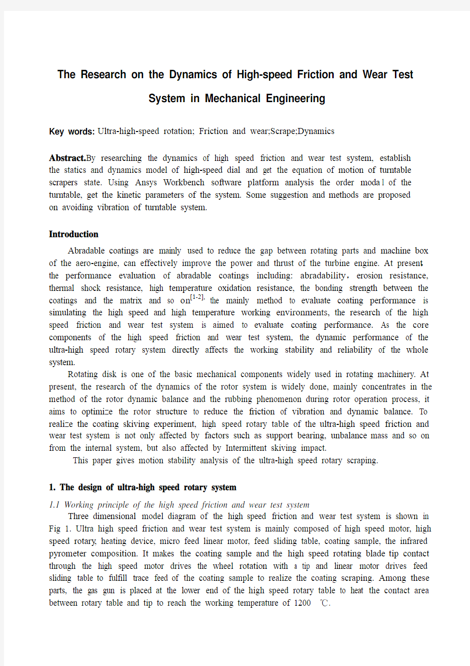
Three dimensional model diagram of the high speed friction and wear test system is shown in Fig 1. Ultra high speed friction and wear test system is mainly composed of high speed motor, high speed rotary, heating device, micro feed linear motor, feed sliding table, coating sample, the infrared pyrometer composition. It makes the coating sample and the high speed rotating blade tip contact through the high speed motor drives the wheel rotation with a tip and linear motor drives feed sliding table to fulfill trace feed of the coating sample to realize the coating scraping. Among these parts, the gas gun is placed at the lower end of the high speed rotary table to heat the contact area between rotary table and tip to reach the working temperature of 1200 ℃.
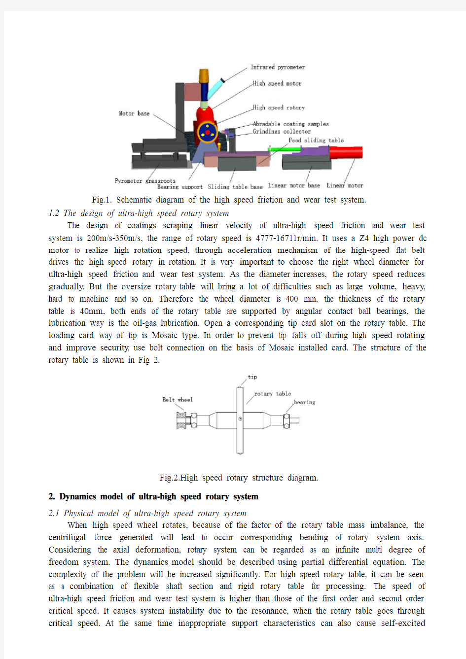
wear test system is 200m/s-350m/s, the range of rotary speed is 4777-16711r/min. It uses a Z4 high power dc motor to realize high rotation speed, through acceleration mechanism of the high-speed flat belt drives the high speed rotary in rotation. It is very important to choose the right wheel diameter for ultra-high speed friction and wear test system. As the diameter increases, the rotary speed reduces gradually. But the oversize rotary table will bring a lot of difficulties such as large volume, heavy, hard to machine and so on. Therefore the wheel diameter is 400 mm, the thickness of the rotary table is 40mm, both ends of the rotary table are supported by angular contact ball bearings, the lubrication way is the oil-gas lubrication. Open a corresponding tip card slot on the rotary table. The loading card way of tip is Mosaic type. In order to prevent tip falls off during high speed rotating and improve security, use bolt connection on the basis of Mosaic installed card. The structure of the rotary table is shown in Fig 2.
2. Dynamics model of ultra-high speed rotary system
2.1 Physical model of ultra-high speed rotary system
When high speed wheel rotates, because of the factor of the rotary table mass imbalance, the centrifugal force generated will lead to occur corresponding bending of rotary system axis. Considering the axial deformation, rotary system can be regarded as an infinite multi degree of freedom system. The dynamics model should be described using partial differential equation. The complexity of the problem will be increased significantly. For high speed rotary table, it can be seen as a combination of flexible shaft section and rigid rotary table for processing. The speed of ultra-high speed friction and wear test system is higher than those of the first order and second order critical speed. It causes system instability due to the resonance, when the rotary table goes through critical speed. At the same time inappropriate support characteristics can also cause self-excited
vibration of the system. Through the lower rotor - bearing - stand system stiffness by using flexible support, it can make the rotor-bearing system go through the critical speed with small amplitude. And this kind of flexible supporting can make the rotor bending vibration decrease in the whole range of speed [3] .Both ends of the rotary table are supported by angular contact ball bearing. Considering the actual bearing stiffness, damping characteristics, we use the vertical and horizontal spring constraints. Spring stiffness is equivalent to bearing stiffness and support stiffness. The damping spring is equivalent to bearing damping and support damping [4].
2.2 mathematical model of ultra-high speed rotary system
The bearing is simulated by isotropic spring and damper and mass imbalance is simulated by lumped mass on the rigid rotary table, we can build the rotor model geometry structure according to it, as shown in Fig.3.
oxyz and inertia (fixed) coordinate system OXYZ. Y shaft of rotating coordinate system oxyz and rotor axis of rotation are the same, x and z axis are defined as the other two main principal axis of inertia, the origin choose in the center of the rotary table. The offset distance between the imbalance mass on the rotary table and shaft is u z ,imbalance mass is mu ,the mass of rotary table is m z , shaft mass is m. Vibration state of the rotary can be described by using geometric center position(X,Z) and angle (,)θ? that shaft relative to X,Z axis. The direction of (,)θ? is respectively from the y and z from y to x .The position of unbalance mass on the rotary table is (u x ,u y ,u z ) in the rotation coordinate system oxyz. The dynamic model that is established in the rotary system is as follows:
2222
2()22(sin cos )(cos sin )()22(cos sin )(sin cos )(cos sin )()22(sin cos z u x z x z z u x z x z x z a b b u y x z m m X cX kX m u u u u m m Z cZ kZ m u u u u u u cL kL I J I I m u u u φφφφφφφφφφφφφφφθθφψθφψφφ??+++=-++??
??+++=+--??
+++-+-=---22
2)(sin cos )()22(cos sin )x z a b b u y x z u u cL kL I J I I m u u u φφφφψψφθψφθφφφ????????
??-+++++=+??++???? (1)
Among it, k 、c are both ends bearing stiffness and damping, L is the rigid rotor shaft length(the distance between the two supporting), I a and I b are respectively the radial and axial moment of inertia, J is the rotary ’s radial moment of inertia, φ is rotation angle of the rotor, the direction is from z to x.
3 .Rotary table dynamics analysis
Among the analysis of the rotor system, the frictional contact of the rotor and the stationary part is the important reason of causing the rotating machinery vibration and noise [5]. High-speed dial rubbing is not the same phenomenon with rubbing referred in the Rotating Machinery, because the high-speed dial rubbing is not just contact in rotor and seal or bearing, the coating scraping contact friction is more important. After the impact, dial response should have rebound movement of the complex transient lateral vibration and torsional vibration. The twisting motion is caused by the impact of torque. The direction of rebound movement is depended on the relative position of the initial movement of the stationary member, the contact surface and the rotor circumferential speed. Rebound movement may be along the precession direction or in opposite directions. The movement after shock is described by the free transverse vibration, its frequency is equal to the rotor natural frequency or multiples [6].
3.1 Rotary table scraping state kinetic analysis models
When the turntable scraps the tip, the specific process is composed by preparing scraping, start scraping, scraping, out from scraping. The reaction force of the turntable and coating in the scraping includes not only radial force F r but also radial force creates friction F μ, there is also coatings tangential force F t and scraping torque M f , rotary table coating scraping force diagram is shown in Fig. 4.
center O 'is r, the exciting force model of rotary table coating scraping is:
r
t F F F F F F M F r
μτμτμ==+= (2)
F t in Formula (2) is the total tangential force by the rotary table.
When the scraping is began, rotary table stiffness will cause a large bending deformation of the rotary table axis, the amount of deformation is e=(x 2+y 2)1/2,the bending stiffness of the shaft is k, the radial direction of the rotor of the maximum amount of deformation is l, so the bending stiffness
of the system is /m k ke l =, bending stiffness coefficient of the X, Y direction is /m rr
rr k k e l =,
Stiffness is competed by k rr and additional stiffness k 0[4] , the additional stiffness is 0()/k k e l l =-, δr is the radial depth of the cut into the coating, β is the displacement of the initial angle, φ + β is the angle of scraping point with the x axis. Since each scraping of the coating of the turntable is occurred in one week in the precession, and ignore the transient process, scraping generates the excitation to the rotor is occurred in periodically step. So we can use the product of cycle step function and excitation force to the system. The cycle step function is expressed as:
1112()1/2sin(/2)cos[(/2]/n i F t t i t i t t i π
??Ω=-Ω-ΩΩ-????
∑ (3)
F requency Ω in formula (3) is equal to the frequency of the processionals motion, t 1 is the continuous impact time and slightly less than 2π / Ω.
11/()t i ααπ=Ω++ (4) 1cos()sin()
y e arctg
x e ?βα?β-Ω+=+Ω+ (5)
Where in α is the dial twist angle in scraping.
Above the excitation force and the step function is applied to the coating scraping turntable, we can achieve the differential equations of motion:
00()sin()()()cos()()()()r rr x r rr y p F Mx D x k x F t k x t F t F My D y k y F t k y t F t F J D k M t M F t ααα?βα?βααα++=-ΩΩ++++Ω++=-ΩΩ++++Ω++=-Ω (6)
In formula (6), M is a turntable quality, D r is damping coefficient for the turntable system, D α is dial torsional damping coefficient, k rr is the bending stiffness of the turntable, and K α is the torsional stiffness of the turntable, k 0 is additional stiffness, M (t) is externally applied to the power torque of the turntable system, J p turn coiled its moment of inertia when the rotation of the center origin O. if we regard the turntable as a uniform quality disc, its moment of inertia is 212p J Mr =.
3.2 Ultra-high-speed dial static analysis
When the ultra-high-speed friction and wear testing system works, the turntable edge of the tip of the line speed can reach 350m / s, the speed of the turntable will also be up to 16711r/min. In such a high speed, the turntable will be subject to a great centrifugal force acts. Under conditions that, we assume the density of the materials is 7.85g/cm 3, calculated in accordance with the maximum intensity theory in engineering mechanics, the highest centrifugal tensile stress is 547.53MPa, this stress has exceeded the structural steel used in the ordinary dial a tensile ultimate strength of 460MPa, the turntable stress cloud under the speed of 16711r/min is shown in Fig.5.
When is the most susceptible damage part, belong to the fragile area. In turntable matrix material selection, material tensile ultimate strength should be greater than 547.53MPa, and try to choose a less dense, otherwise, the incorrect material selection will result in rotation speed to reach or exceed the speed of damage, it will cause danger to the safety of equipment and personnel. To make the turntable rotation be safe and reliable, select the high-temperature alloy GH985 as a turntable base material.
3.3 Ultra-high-speed dial kinetic analysis
Based on static analysis, do the dynamics analysis of dial system first is the modal analysis and harmonic analysis of turntable system. Mode is inherent in the mechanical structure of the vibration characteristics, each mode has a specific natural frequency, damping ratios and mode shapes. These modal parameters can be achieved by calculation or test analysis, such a calculation or test analysis process is known as modal analysis [7]. Do modal analysis of the dial overall after tip installed, the mode number is set to 10, obtain first 10 natural frequencies and the corresponding mode shapes of carousel system in the state of no external load constraints.
The sixth-order natural frequency range of the rotor is 0Hz~ 2.29e-03Hz, the seventh order natural frequency suddenly surged to 1022.4Hz, the tenth-order natural frequency up to 1183Hz. When the rotor frequency of the experimental system reaches this range, the carousel system occurs resonance. During the acceleration of the carousel system, low speed dial torsional vibration occurs more obvious, as the speed increases, the shaft produces a more significant bending vibration. The normal operating frequency of the ultra-high-speed friction and wear testing system is above 1700Hz, so, the test system can be effectively avoided resonance phenomenon in the scraping experiments.
Following the modal analysis of the rotor system, you need to do the corresponding harmonic response analysis on rotary table’s vibration frequency. The so-called harmonic response analysis is the technology that it can be used to determine the linear structure’s steady-state response when the linear structure is bearing a load with sinusoidal (harmonic) changes. During the rotary table harmonic analysis process, you need to set the frequency range of the dial system and set the external load that the rotary table system bears. Assuming the same as the rotational frequency of the rotary table and the system is 1752Hz, so the set frequency ranges 0-1752Hz. Vibration amplitude at the frequency of 1183Hz reached 2.32e-3mmm.And when the amplitude reaches the highest peak, the phase angle has risen to the highest value-180°.That means in this frequency rotary table’s torsional vibration p henomenon is strong.
4 .Conclusions
(1) When the ultra-high-speed friction and wear testing system works, turntable system is at ultra-high speed, shaft will occur significant vibration. Turntable starts from rest, in the acceleration
phase, due to the presence of angular acceleration, vibration is more intense; when the dial is rotated to achieve the required speed for constant speed rotation, the vibration is weakened.
(2) When the scraping happens between the dial and the coating, dial response should have complex transient lateral and torsional vibrations. When scraping happens between the tip and the coating, the carousel system bending vibration and torsional vibration occur simultaneously,and bending vibrations of the dial system response associates with torsional vibration, the torsional vibration response changes only relate to the time of producing coatings scraping, regardless of the bending vibration.
(3) The natural frequency of the turntable inclines to the vibration frequency when the dial works properly, but in dial accelerated process we should try to shorten the acceleration time of the turntable in the resonance region.
References
[1]Zhang Deming, Ren Xianjing, Teng Baiqiu. Research Progress on Performance Evaluation Techniques of Abradable Seal Coatings[J]. Thermal Spray Technology, 2009, 1 (2):19-22.
[2]LIU Junhai, He Jiawen, Lu Mingzhu. A New Method for Evaluation of Mechanica l Properties of Sealing Coating[J]. Materials Engineering, 1997, (11):43-44.
[3]Ke LiZONG,QImansiji. Rotor dynamics elastic support [M]. Beijing: Science Press, 1987.
[4]HAN Y anguang. The Numerical Experimentation and Analysis of Dynamic Balance for High Speed Rotors[D]. Huazhong University of Science and Technology, 2008:1-94.
[5]Edwards S, Lees A W, Friswell M I. The Influence of Torsion on Rotor/Stator Contact in Rotating Machinery[J]. Journal of Sound and Vibration, 1999, 225(4): 767-778.
[6]HU Niaoqing. Research on Identification of Nonlinear and Fault of Rub-impact in Rotors[D]. National Defenes University of Science and Technology, 2001: 24-35.
[7]PU Guangyi. ANSYS WORKBENCH 12 Basic tutorial with example explanation[M]. Beijing: China WaterPower Press, 2010, 10.
药物动力学模型 数学建模
药物动力学模型 一般说来,一种药物要发挥其治疗疾病的作用,必须进入血液,随着血流到达作用部位。药物从给药部位进入血液循环的过程称为药物的吸收,而借助于血液循环往体内各脏器组织转运的过程称为药物的分布。 药物进入体内以后,有的以厡型发挥作用,并以厡型经肾脏排出体外;有的则发生化学结构的改变--称为药物的代谢。代谢产物可能具有药理活性,可能没有药理活性。不论是厡型药物或其代谢产物,最终都是经过一定的途径(如肾脏、胆道、呼吸器官、唾液腺、汗腺等)离开机体,这一过程称为药物的排泄。有时,把代谢和排泄统称为消除。 药物动力学(Pharmacokinetics)就是研究药物、毒物及其代谢物在体内的吸收、分布、代谢及排除过程的定量规律的科学。它是介于数学与药理学之间的一门新兴的边缘学科。自从20世纪30年代Teorell 为药物动力学奠定基础以来,由于药物分析技术的进步和电子计算机的使用,药物动力学在理论和应用两方面都获得迅速的发展。至今,药物动力学仍在不断地向深度和广度发展。药物动力学的研究方法一般有房室分析;矩分析;非线性药物动力学模型;生理药
物动力学模型;药物药效学模型。下面我们仅就房室分析作一简单介绍。 为了揭示药物在体内吸收、分布、代谢及排泄过程的定量规律,通常从给药后的一系列时间 (t) 采取血样,测定血(常为血浆,有时为血清或全血)中的药物浓度( C );然后对血药浓度——时间数据数据(C——t数据)进行分析。 一一室模型 最简单的房室模型是一室模型。采用一室模型,意味着可以近似地把机体看成一个动力学单元,它适用于给药后,药物瞬间分布到血液、其它体液及各器官、组织中,并达成动态平衡的情况。下面的图(一)表示几种常见的给药途径下的一室模型,其中C代表在给药后时间t的血药浓度,V代表房室的容积,常称为药物的表观分布容积,K代表药物的一级消除速率常数,故消除速率与体内药量成正比,D代表所给刘剂量。 图(a)表示快速静脉注射一个剂量D,由于是快速,且药物直接从静脉输入,故吸收过程可略而不计;图(b)表示以恒定的速率K,静脉滴注一个剂量D;若滴注所需时间为丅,则K=D/丅。图(c)表示口服或肌肉注射一个剂量D,由于存在吸收过程,故图中分别
人体动力学模型与仿真研究
基于ADAMS人体动力学下肢建模与仿真 前言 人体生物力学研究的是一个多学科交叉的新兴领域,它涉及到机器人机构学、运动学、动力学、人体解剖学、外科学(特别是骨科)、摄影测量学、测试技术以及计算机辅助设计等多方面的知识。研究人体动力学的建模和仿真,获取有关运动、力学数据,对指导机电产品设计、运动康复机械设计等具有重要意义。为了满足人们的需要和安全,在一些实验中必须模拟人体作为实验对象。为了保证人体的安全和新设备的研发,因此在人体运动仿真研究中需要将人体作为某种程度的抽象,这种抽象既要尽可能反映人体的真实情况,又要易于实现。人体模型是车辆设计、动力学分析和服务型机器人设计与仿真的基础,为设计用的人体模型属于人体几何学/运动学模型,它还为动力学分析与仿真提供了必要的几何特性;为分析与仿真用的人体模型属于多体系统动力学模型。人体动力学模型是多体系统动力学在生物力学方面的最新研究成果,已在国外车辆动力学分析与仿真领域获得工程应用。如果从建模的方式来看人体模型种类可以分为以下两种。从仿真角度建模—人体仿真模型(目前主要是指运用计算机仿真软件进行人体多体仿真建模);从力学角度建模—动力学模型。 一、历史发展及现状 1.运动生物力学的国内外发展现状 有关生物体运动的力学问题很早就引起了人们的注意,早在15世纪末,意大利科学家Leonardo Da Vinci研究了人体的各种姿势和
运动,首先提出了“一切能够运动的生物体都遵循力学定律而运动”的重要观点。随着生命科学、力学和计算机技术的飞速发展,一门以研究人体力学行为特征为主的学科一运动生物力学诞生了。 运动生物力学作为一门学科,它的产生与发展,在我国还只有不到60年的历史。直到70年代后期,随着体育科学的全面进步和高科技的渗入,运动生物力学才真正活跃起来,并迅即发展成为体育科学体系中最体现现代高科技水平的学科之一。考察并分析运动生物力学的发展过程,在欣喜于运动生物力学已取得长足进步的同时, 我们还不得不承认,运动生物力学的理论基础是不完善的,在这方面的科学研究也几无进展。 人体运动分析是近年来计算机视觉领域中备受关注的前沿方向之一,是当代生物力学和计算机视觉相结合的一项重要技术,具有十分广阔和重要的应用领域,它在机器人学、仿生机械学、智能控制、人机交互、运动分析和虚拟现实等领域都有着广泛的应用。建模是研究人体运动的核心,目前的建模方法包括:有限元分析,多刚体动力学,肌肉一骨骼建模,振动力学,运动学建模以及实验等方法。 2.多体系统动力学研究的发展 多体系统动力学的核心问题是建模和求解问题,其系统研究开始于20世纪60年代。从60年代到80年代,侧重于多刚体系统的研究,主要是研究多刚体系统的自动建模和数值求解。 到了80年代中期,多刚体系统动力学的研究已取得一系列的成果,尤其是建模理论趋于成熟,但更稳定,更有效的数值求解仍然是
研究控制非线性动力学模型
Study on Nonlinear Dynamical Model and Control Strategy of Transient Process in Hydropower Station with Francis turbine Haiyan Bao , Jiandong Yang, Liang Fu State Key Laboratory of Water Resources and Hydropower Engineering Science, Wuhan University No.8 Donghu South Road, Wuchang District, Wuhan 430072, China Haiyan_8931@https://www.360docs.net/doc/194013740.html, Abstract —The transient process in conduits of hydropower stations is a very complicated dynamic procedure coupled with fluid, machines, electricity. In this paper, a whole nonlinear dynamical model of transient process in hydropower station with Francis turbine has been developed, and the control strategies of each transient process are studied. The nonlinear characteristics of hydraulic turbine and the elastic water hammer effect of pressure water supply conduit are considered in the model. The developed model is accurate enough to represent and simulate each transient process of the plant and may enable a plant operator to carry out economical, convenient study for the static stability and transient stability of the hydropower station under a wide range of transient processes. In addition, the literature takes a hydropower station as engineering case to simulate the transient processes of hydro-generator units ’ start-up, load variation, full load rejection from the grid and emergency stop. And the results of simulation are very satisfied. Keywords-hydraulic transients; nonlinear mathematical model; numerical simulation; control strategy I.I NTRODUCTION H ydropower is an important and vital renewable energy resource, which converts energy in flowing water into electricity. Generally, a hydro-generator unit has many different operating conditions, and any operating condition changes will result in different hydraulic transients. The calculation of hydraulic transient is a key link for the safety and reliability of units and hydraulic installations. Traditionally, the objective of hydraulic transient calculation is to predict three primary regulation guaranteed parameters including the maximum dynamic pressure in the spiral case, the maximum rising ratio of rotating speed and the draft tube minimum pressure, consequently to ensure safety operation of hydropower station. H owever, with the development of hydroelectric construction and technology in China, the content of hydraulic transient calculation is continuously being enriched, it already not only include calculation of regulation guaranteed parameters, but also include calculation and research of stabilization and dynamic quality [1]. In conventional hydropower stations, there are a series of hydraulic transient processes, such as start-up, load variation, full load rejection from the grid, and emergency stop, where power and frequency regulations may always be needed [2]. In order to design suitable control law, stabilize the nonlinear systems, solve many existing control problems, reduce operating costs and energy losses, and improve guarantee security and safety of equipments and plants, it is necessary to develop a whole nonlinear dynamical model that is accurate enough to represent and simulate each transient process of the plant. The developed model may enable a control system designer or a plant operator to carry out accurate, economical, convenient study for the static stability and transient stability of the hydropower station under a wide range of operational modes and nonlinear process conditions, and to design the suitable control strategy, so as to improve stability of hydro-generator units. The literature review carried out in this work finds some published research works. In [3], a new kind of start-up rule is proposed, by using this rule the contradiction between fast start-up and smooth start-up is eliminated; In [4], it analyses the adjusting mode of power adjustment in digital electric-hydraulic governor, and how to realize power adjustment; In [5], the transient performance index of hydro-generator unit in a full load rejection are studied. owever, in the aforementioned published research works, the effect of hydraulic turbine characteristics and the elasticity of conduit walls on the transient process are neglected . In addition, a whole nonlinear dynamical model that can simulate each transient process of the plant isn’t developed in predecessors’ research works. In china, some large-scale hydropower stations often use the complex arrangement nowadays, moreover, the hydraulic conduits are getting longer, and its nonlinearity is very obvious. Therefore, it is very important and necessary to develop a whole nonlinear dynamical model for the complex hydropower system. II.M ATHEMATICAL M ODELS For developing the whole nonlinear mathematical model, the hydropower plant system is decomposed into decoupled dynamical modules as illustrated in Fig. 1, and a mathematical model for each module is developed. 978-1-4244-2487-0/09/$25.00 ?2009 IEEE
系统动力学模型
第10章系统动力学模型 系统动力学模型(System Dynamic)是社会、经济、规划、军事等许多领域进行战略研究的重要工具,如同物理实验室、化学实验室一样,也被称之为战略研究实验室,自从问世以来,可以说是硕果累累。 1 系统动力学概述 2 系统动力学的基础知识 3 系统动力学模型 第1节系统动力学概述 1.1 概念 系统动力学是一门分析研究复杂反馈系统动态行为的系统科学方法,它是系统科学的一个分支,也是一门沟通自然科学和社会科学领域的横向学科,实质上就是分析研究复杂反馈大系统的计算仿真方法。 系统动力学模型是指以系统动力学的理论与方法为指导,建立用以研究复杂地理系统动态行为的计算机仿真模型体系,其主要含义如下: 1 系统动力学模型的理论基础是系统动力学的理论和方法; 2 系统动力学模型的研究对象是复杂反馈大系统; 3 系统动力学模型的研究内容是社会经济系统发展的战略与决策问题,故称之为计算机仿真法的“战略与策略实验室”; 4 系统动力学模型的研究方法是计算机仿真实验法,但要有计算
机仿真语言DYNAMIC的支持,如:PD PLUS,VENSIM等的支持; 5 系统动力学模型的关键任务是建立系统动力学模型体系; 6 系统动力学模型的最终目的是社会经济系统中的战略与策略决策问题计算机仿真实验结果,即坐标图象和二维报表; 系统动力学模型建立的一般步骤是:明确问题,绘制因果关系图,绘制系统动力学模型流图,建立系统动力学模型,仿真实验,检验或修改模型或参数,战略分析与决策。 地理系统也是一个复杂的动态系统,因此,许多地理学者认为应用系统动力学进行地理研究将有极大潜力,并积极开展了区域发展,城市发展,环境规划等方面的推广应用工作,因此,各类地理系统动力学模型即应运而生。 1.2 发展概况 系统动力学是在20世纪50年代末由美国麻省理工学院史隆管理学院教授福雷斯特(JAY.W.FORRESTER)提出来的。目前,风靡全世界,成为社会科学重要实验手段,它已广泛应用于社会经济管理科技和生态灯各个领域。福雷斯特教授及其助手运用系统动力学方法对全球问题,城市发展,企业管理等领域进行了卓有成效的研究,接连发表了《工业动力学》,《城市动力学》,《世界动力学》,《增长的极限》等著作,引起了世界各国政府和科学家的普遍关注。 在我国关于系统动力学方面的研究始于1980年,后来,陆续做了大量的工作,主要表现如下: 1)人才培养
动力学模型
月球软着陆控制系统综合仿真及分析(课程设计) 在月球探测带来巨大利益的驱使下,世界各国纷纷出台了自己的探月计划,再一次掀起了新一轮探月高潮。在月球上着陆分为两种,一种称为硬着陆,顾名思义,就是探测器在接近月球时不利用制动发动机减速而直接撞击月球。另一种称为软着陆,这种着陆方式要求探测器在距月面一定高度时开启制动系统,把探测器的速度抵消至零,然后利用小推力发动机把探测器对月速度控制在很小的范围内,从而使其在着陆时的速度具有几米每秒的数量级。显然,对于科学研究,对探测器实施月球软着陆的科学价值要大于硬着陆。 1月球软着陆过程分析 目前月球软着陆方式主要有以下两种方式: 第一种就是直接着陆的方式。探测器沿着击中轨道飞向月球,然后在适当的月面高度实施制动减速,最终使探测器软着陆于月球表面。采用该方案时,探测器需要在距离目标点很远时就选定着陆点,并进行轨道修正。不难发现,该方法所选的着陆点只限于月球表面上接近轨道能够击中的区域,所以能够选择的月面着陆点的区域是相当有限的。 第二种方法就是先经过一条绕月停泊轨道,然后再伺机制动下降到月球表面,如图17-1所示。探测器首先沿着飞月轨道飞向月球,在距月球表面一定高度时,动力系统给探测器施加一制动脉冲,使其进入一条绕月运行的停泊轨道;然后根据事先选好的着陆点,选择霍曼变轨起始点,给探测器施加一制动脉冲,使其进入一条椭圆形的下降轨道,最后在近月点实施制动减速以实现软着陆。 主制动段 开始点 图17-1 月球软着陆过程示意图 与第一种方法相比,第二种方法有以下几个方面较大的优越性: 1)探测器可以不受事先选定着陆点的约束,可以在停泊轨道上选择最佳的着陆点,具有很大的选择余地。
系统动力学模型案例分析
系统动力学模型介绍 1.系统动力学的思想、方法 系统动力学对实际系统的构模和模拟是从系统的结构和功能两方面同时进行的。系统的结构是指系统所包含的各单元以及各单元之间的相互作用与相互关系。而系统的功能是指系统中各单元本身及各单元之间相互作用的秩序、结构和功能,分别表征了系统的组织和系统的行为,它们是相对独立的,又可以在—定条件下互相转化。所以在系统模拟时既要考虑到系统结构方面的要素又要考虑到系统功能方面的因素,才能比较准确地反映出实际系统的基本规律。系统动力学方法从构造系统最基本的微观结构入手构造系统模型。其中不仅要从功能方面考察模型的行为特性与实际系统中测量到的系统变量的各数据、图表的吻合程度,而且还要从结构方面考察模型中各单元相互联系和相互作用关系与实际系统结构的一致程度。模拟过程中所需的系统功能方面的信息,可以通过收集,分析系统的历史数据资料来获得,是属定量方面的信息,而所需的系统结构方面的信息则依赖于模型构造者对实际系统运动机制的认识和理解程度,其中也包含着大量的实际工作经验,是属定性方面的信息。因此,系统动力学对系统的结构和功能同时模拟的方法,实质上就是充分利用了实际系统定性和定量两方面的信息,并将它们有机地融合在一起,合理有效地构造出能较好地反映实际系统的模型。 2.建模原理与步骤
(1)建模原理 用系统动力学方法进行建模最根本的指导思想就是系统动力学的系统观和方法论。系统动力学认为系统具有整体性、相关性、等级性和相似性。系统内部的反馈结构和机制决定了系统的行为特性,任何复杂的大系统都可以由多个系统最基本的信息反馈回路按某种方式联结而成。系统动力学模型的系统目标就是针对实际应用情况,从变化和发展的角度去解决系统问题。系统动力学构模和模拟的一个最主要的特点,就是实现结构和功能的双模拟,因此系统分解与系统综合原则的正确贯彻必须贯穿于系统构模、模拟与测试的整个过程中。与其它模型一样,系统动力学模型也只是实际系统某些本质特征的简化和代表,而不是原原本本地翻译或复制。因此,在构造系统动力学模型的过程中,必须注意把握大局,抓主要矛盾,合理地定义系统变量和确定系统边界。系统动力学模型的一致性和有效性的检验,有一整套定性、定量的方法,如结构和参数的灵敏度分析,极端条件下的模拟试验和统计方法检验等等,但评价一个模型优劣程度的最终标准是客观实践,而实践的检验是长期的,不是一二次就可以完成的。因此,一个即使是精心构造出来的模型也必须在以后的应用中不断修改、不断完善,以适应实际系统新的变化和新的目标。 (2)建模步骤 系统动力学构模过程是一个认识问题和解决问题的过程,根据人们对客观事物认识的规律,这是一个波浪式前进、螺旋式上升的过程,因此它必须是一个由粗到细,由表及里,多次循环,不断深化的过程。系统动力学将整个构模过程归纳为系统分析、结构分析、模型建立、模型试验和模型使用五大步骤这五大步骤有一定的先后次序,但按照构模过程中的具体情况,它们又都是交叉、反复进行的。 第一步系统分析的主要任务是明确系统问题,广泛收集解决系统问题的有关数据、资料和信息,然后大致划定系统的边界。 第二步结构分析的注意力集中在系统的结构分解、确定系统变量和信息反馈机制。 第三步模型建立是系统结构的量化过程(建立模型方程进行量化)。 第四步模型试验是借助于计算机对模型进行模拟试验和调试,经过对模型各种性能指标的评估不断修改、完善模型。 第五步模型使用是在已经建立起来的模型上对系统问题进行定量的分析研究和做各种政策实验。 3.建模工具 系统动力学软件VENSIM PLE软件 4.建模方法 因果关系图法 在因果关系图中,各变量彼此之间的因果关系是用因果链来连接的。因果链是一个带箭头的实线(直线或弧线),箭头方向表示因果关系的作用方向,箭头旁标有“+”或“-”号,分别表示两种极性的因果链。
吸附热力学及动力学的研究
吸附热力学及动力学的研究 摘要: 杂乱无章的实验数据, 不经过数学处理, 得不到能够描述它们的模型,其本身无论在科学理论上,还是在应用技术上都没有太大的实际意义。本文综述了近些年来在液固吸附理论研究领域对吸附等温线,吸附热力学及吸附动力学的研究进展。论述5 种类型吸附等温线,总结了热力学中△H 、△G 、△S 的几种求算方法,以及5种吸附动力学的模型,从而,为吸附实验数据的处理和模型优选,,提供依据。 关键字:吸附 等温曲线 热力学 动力学 1吸附等温曲线 吸附等温曲线是指在一定温度下溶质分子在两相界面上进行的吸附过程达到平衡时它们在两相中浓度之间的关系曲线。在一定温度下, 分离物质在液相和固相中的浓度关系可用吸附方程式来表示。作为吸附现象方面的特性有吸附量、吸附强度、吸附状态等, 而宏观地总括这些特性的是吸附等温线.[1] 1.1Langmuir 型分子吸附模型 Langmuir 吸附模型是应用最为广泛的分子吸附模型,Langmuir 型分子吸附模型[2]就是在Langmuir 吸附模型的基础上,研究者就Langmuir 吸附模型的局限性进行了改进、发展,形成了一系列的分子吸附模型。 1. 1.1 Langmuir 分子吸附模型 Langmuir 分子吸附模型是根据分子间力随距离的增加而迅速下降的事实,提出气体分子只有碰撞固体表面与固体分子接触时才有可能被吸附,即气体分子与表面相接触是吸附的先决条件。并做如下假定: ①气体只能在固体表面上呈单分子层吸附; ②固体表面的吸附作用是均匀的; ③被吸附分子之间无相互作用。所以Langnuir 等温吸附方程[3 ] c K c q q d m +≡ 或c K c K q q b b m +≡ 1 (1) 其中,qm 为饱和吸附容量,Kd 为吸附平衡的解离常数,Kb 为结合常数( = 1/ Kd) 。 Langnuir 分子吸附模型对于当固体表面的吸附作用相当均匀,且吸附限于单分子层时,能够较好的代表试验结果。但由于它的假定是不够严格的,具有相当的
吸附动力学和热力学各模型公式及特点
分配系数 K d = (C 0?C e )V e 吸附量 Q t =C 0?C t m ×V Langmiur Q e =Q m K L C e L e C e Q e =1Q m K L +C e Q m KL 是个常数与吸附剂结合位点的亲和力有关,该模型只对均匀表面有效 Freundlich Q e =K F C e 1/n ln Q e =ln K F +1n ln C e Ce 反应达到平衡时溶液中残留溶质的浓度 KF 和n 是Freundlich 常数,其中KF 与吸附剂的吸附亲和力大小有关,n 指示吸附过程的支持力。1/n 越小吸附性能越好一般认为其在0.1~0.5时,吸附比较容易;大于2时,难以吸附。 应用最普遍,但是它适用于高度不均匀表面,而且仅对限制浓度范围(低浓度)的吸附数据有效 一级动力学1(1)k t t e q q e -=- Q t =Q e (1?e ?K 1t ) 线性ln Q e ?Q t =ln Q e ?K 1t 二级动力学2221e t e k q t q k q t =+ Q t =K 2Q e 2t 1+K 2Q e t 线性t Q t =1K 2Q e 2+t Q e 初始吸附速度V 0=K 2Q e 2 Elovich 动力学模型 Q t =a +b ln t Webber-Morris 动力学模型 Q t =K ip t 1/2+c Boyd kinetic plot Q t e =1?6×exp ?K B t 6 令F=Q t /Q e,
K B t=-0.498-ln(1-F) 准一级模型基于假定吸附受扩散步骤控制; 准二级动力学模型假设吸附速率由吸附剂表面未被占有的吸附空位数目的平方值决定,吸附过程受化学吸附机理的控制,这种化学吸附涉及到吸附剂与吸附质之间的电子共用或电子转移; Webber-Morris动力学模型 粒子内扩散模型中,qt与t1/2进行线性拟合,如果直线通过原点,说明颗粒内扩散是控制吸附过程的限速步骤;如果不通过原点,吸附过程受其它吸附阶段的共同控制;该模型能够描述大多数吸附过程,但是,由于吸附初期和末期物质传递的差异,试验结果往往不能完全符合拟合直线通过原点的理想情况。粒子内扩散模型最适合描述物质在颗粒内部扩散过程的动力学,而对于颗粒表面、液体膜内扩散的过程往往不适合 Elovich方程为一经验式,描述的是包括一系列反应机制的过程,如溶质在溶液体相或界面处的扩散、表面的活化与去活化作用等,它非常适用于反应过程中活化能变化较大的过程,如土壤和沉积物界面上的过程。此外,Elovich方程还能够揭示其他动力学方程所忽视的数据的不规则性。 Elovich和双常数模型适合于复非均相的扩散过程。 Langmuir模型假定吸附剂表面均匀,吸附质之间没有相互作用,吸附是单层吸附,即吸附只发生在吸附剂的外表面。Qm 为饱和吸附量,表示单位吸附剂表面,全部铺满单分子层吸附剂时的吸附量;该模型的假设对实验条件的变化比较敏感,一旦条件发生变化,模型参数则要作相应的改变,因此该模型只能适用于单分子层化学吸附的情况。Langmuir 等温吸附模型作为第一个对吸附机理做了生动形象描述的模型,为以后其他吸附模型的建立起到了奠基作用。 Freundlich吸附方程既可以应用于单层吸附,也可以应用于不均匀表面的吸附情况。Freundlich吸附方程作为一个不均匀表面的经验吸附等温式,既能很好的描述不均匀表面的吸附机理,更适用于低浓度的吸附情况,它能够在更广的浓度范围内很好地解释实验结果。但是,Freundlich 吸附方程的缺点则是不能得出一个最大吸附量,无法估算在参数的浓度范围以外的吸附作用。 由于Freundlich 等温吸附方程受低浓度的限制,而Langmuir 等温吸附方程则受高浓度的限制。Redlich–Peterson 等温吸附方程则是综合Freundlich 等温吸附方程和Langmuir 等温吸附方程而提出的较合理的经验方程。A 是一个与吸附量有关的常数,B 也是一个与吸