新型PDC钻头设计(英)
新型PDC钻头设计(英)
时间:2008-12-30 振威石油网关注度:24129
简介:最近推出的新型PDC钻头,在质量上有了很大提高。主要介绍了史密斯钻头公司,Diamant Drilling Services等知名钻头公司推出的新型PDC钻头。
While roller cone bit technology still continues to make advances in insert shape, carbide composition and hydraulics design.
Roller cone and PDC bit design has progressed from its fundamental foundation laid nearly fifty years ago. Factors such as depth of cut, cone offset angle, cone geometry, journal angle, tooth/insert count and spacing are still a part of this foundation. Modern design, as shown by the new products presented in this article, focus on details such as bearing configuration, bottomhole coverage and inter-insert (teeth) clearance relative to adjacent cones. Modern design focuses on modeling cone tracking as a measure of bottomhole clearance. Bit designers rely not only on bit run simulations in a particular formation, some simulate the effect of the BHA on the particular bit to get a complete picture of forces affecting bit performance. As new bits are introduced, they are also accompanied by ancillary services such as custom designing each bit to a particular application. The following new designs show that this will be the continuing trend.
NEW TECHNOLOGY OVERVIEW
The following companies have released new technology within the past year.
United Diamond and Ulterra Drilling Technologies. The TorkBuster torsional impact generator from United Diamond and Ulterra Drilling Technologies enables PDC bits to drill tough formations by supplying impact energy. “When a PDC b it enters high-compressive strength formations, there is a possibility for stick-slip to occur. If insufficient torque is available to fail the formation, the drill string will wind up and store energy,” Rick Dudman, Downhole Tool Manager at Ulterra/United Diamond, explains. “Once the energy required to shear the formation is accumulated, the rock shears and triggers a violent release of stored energy that causes higher-than-normal impact loads on the PDC cutters. This will cause chipping and de-lamination of the diamond surface, eventually leading to a damaged bit and a shortened run.”
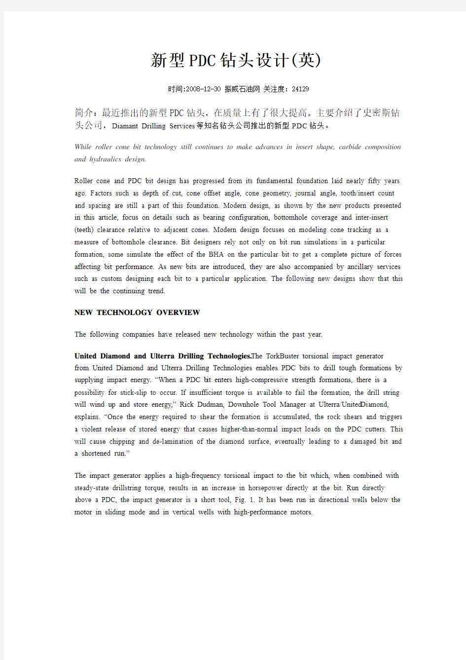
The impact generator applies a high-frequency torsional impact to the bit which, when combined with steady-state drillstring torque, results in an increase in horsepower directly at the bit. Run directly above a PDC, the impact generator is a short tool, Fig. 1. It has been run in directional wells below the motor in sliding mode and in vertical wells with high-performance motors.
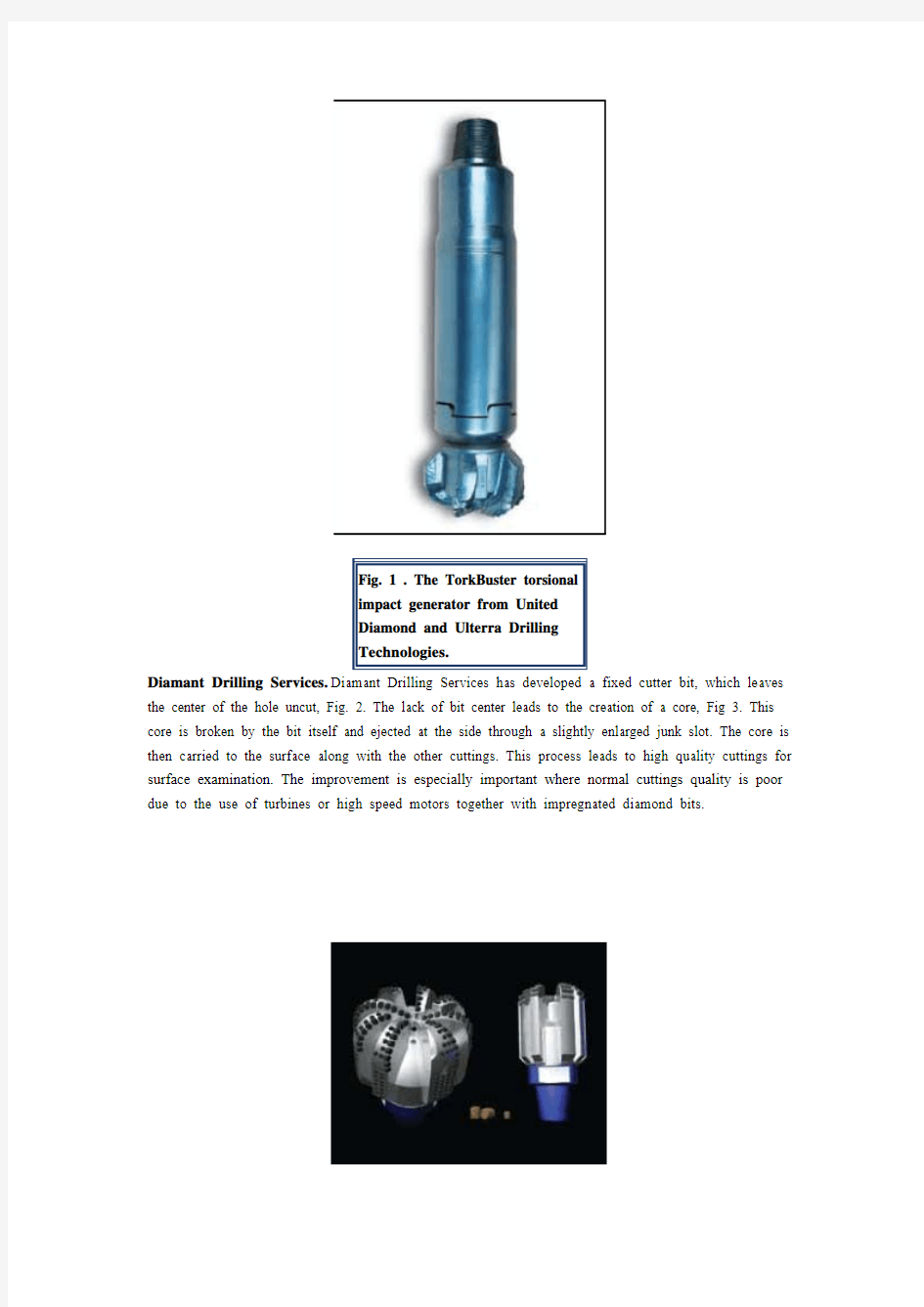
Diamant Drilling Services. Diamant Drilling Services has developed a fixed cutter bit, which leaves the center of the hole uncut, Fig. 2. The lack of bit center leads to the creation of a core, Fig 3. This core is broken by the bit itself and ejected at the side through a slightly enlarged junk slot. The core is then carried to the surface along with the other cuttings. This process leads to high quality cuttings for surface examination. The improvement is especially important where normal cuttings quality is poor due to the use of turbines or high speed motors together with impregnated diamond bits.
The coring feature can be incorporated into impregnated diamond and PDC bits, Fig. 4.
Smith Bits. Smith Bits recently introduced the Shamal Typhoon (ST) product line of roller cone drillbits, developed specifically for the unique challenges of Middle East drilling applications. This product line was developed because vast regions of the Middle East are transitioning into mature drilling provinces. One such opportunity for improving economics is in the large, upper-hole sections drilled through relatively soft formations with technologies that deliver increased performance and decreased risk.
A study of the lithology/rock strength was undertaken to determine shale type/content and compressive strengths of formations drilled in a typical 17-1/2-in. and 16-in. section using Smith’s Drill Bit Optimization System (DBOS), followed by exhaustive dull grading of bits run in the target application.
A systematic hydraulics analysis was also performed to provide conclusive insight into the specific factors that control ROP-performance gains in the target application. The results of this analysis provided the basis for the new bit designs.
Technology platform. The ST platform is based on the synergistic combination of 13 patented and six patent-pending technologies including innovative cutting structures, a new hydraulics system, innovative insert geometries and the latest carbide materials.
CFD analysis. The hydraulic system was developed using Computational Fluid Dynamics (CFD) analysis techniques to evaluate fluid flow, to optimized cuttings removal and ensure the cutting structure is always drilling virgin formation. Specifically, the CFD modeling analysis was carried out to maximize ROP by balancing hydraulic flow, minimizing cuttings residence time and minimizing cuttings recirculation. CFD modeling analysis also minimized erosion by optimizing and controlling fluid velocity.
Nozzle systems. As a result of the in-depth CFD and field analysis, Smith engineering developed ST’s unique six nozzle hydraulics systems consisting of three vectored extended outer nozzles and three dome jet inner nozzles to deliver the optimum hydraulic solution, Fig. 5. The main hydraulics system directs fluid flow to the leading edge of the cones for exceptional gauge row cleaning without contributing to cone shell erosion. The dome jets are pointed at the mid and inner cutting rows but are located far enough from the cone to avoid steel erosion/lost inserts common with the traditional center jet. The combined effect of these six precisely oriented flow patterns creates significant improvements in the path and velocity of the drilling fluid. The system provides an optimized solution for bit and/or bottom hole balling environments or any combination of the two.
Cutting structure. Shamal Typhoon design engineers precisely calculated insert geometry and row positioning to achieve the ideal balance between maximizing ROP while retaining a high level of durability, Fig. 6. The new row geometry is complemented by an array of insert shapes that enable tailoring a bit’s cutting structure to ensure optimal ROP performance, Fig. 7. The Inciso is the latest insert shape and joins the Dogbone, ACE, and chisel inserts. Engineers can use a combination of insert geometries on a single design in order to fine-tune a bit to the operator’s application-specific requirements.
New carbide grades. Smith Bits is a broad range of proprietary carbide grades with unique microstructure characteristics that offer the difficult-to-achieve balance of impact durability and
abr asion resistance. These systematic advances enable the ST bit’s new carbide grades to provide significant increases in fracture toughness compared to those used in the original Shamal product line.
IDEAS . As an integral part of the Shamal Typhoon design process, engineers modeled and certified the performance of the ST bit in Smith’s Integrated Dynamic Engineering Analysis System (IDEAS). IDEAS is a comprehensive time-based 4D modeling tool that accurately predicts a bit’s performance and behavior using finite element analysis, laboratory-derived drilling mechanics and physical input data that accurately characterizes the attributes of the total drilling system. The accuracy of the IDEAS system then allows the designer to certify the performance in a virtual environment so the operator is assured the bit will meet their performance objectives.
Halliburton Security DBS Drill Bits. With introduction of new Direction by Design software, Security DBS Drill Bits provides a tool that quantifies the effects of even slight design changes on the ability of a bit to drill a deviated well-before the bit is built.
In this front-end approach to design engineering, Security DBS applies accumulated knowledge through a proven bit design platform that provides the unique ab ility to “model, measure and optimize”
a design before the bit is ever run. Instead of trial and error, customers benefit from “art to part” engineering, so that what is designed is what is run in the field.
‘Art to part’ vs. trial and error. Incorporating first-hand customer input into the bit design function, Security DBS Application Design Evaluation (ADE) service specialists work directly with the customer to define application-specific bit solutions that account for both how the bit will be steered and how it interacts with the formation to be drilled. For example, the recognized benefits of controlling torque by limiting cutter engagement long ago made depth of cut a standard consideration in PDC bit design. Today, however, front-end engineering enables Security DBS bit designers to
determine precisely how much to limit depth of cut, why to limit it, and when to do so - while always taking into account the directional tendencies of the bit.
Further advancing design engineering for optimal directional performance, the new Direction by Design software determines the effects of bit geometry parameters on steerability and walk rate for a given bit according to the specific drilling system used.
Where previous kinematics models represented bit motion by axial penetration rate, rotational speed and lateral penetration rate or side cutting, the design software meshes specific bit design features and formation characteristics in three dimensions, and simultaneously uses bit rotation, axial penetration, tilting motion, and formation properties to simulate the bit/formation interaction, Fig. 8.
In terms of directional bit design, this enables designers to predict side force required, walk force and speed in azimuth direction for a specific bit design in a given drilling application. In addition, bit torque variance during directional drilling is calculated to account for different bit behaviors during kick-off, build and hold drilling modes. The new cutter/rock interaction model at the heart of the design software enables directional drill bits to be designed with optimum bit walk characteristics for drilling a specific wellbore profile with a specific drilling system. As a result, PDC bit designs can be optimized and sent to the field with directional performance attributes already known before the bit is ever run in hole.
Bit-Tech SPH. The B45T is Bit-Tech SPH’s new drillbit series, Figs. 9 and 10. Scott Strange, Bit-Tech SPH president, says the new series has an additional patent-pending, back-to-back, 13-mm and 11-mm
tandem-cutter arrangement that will be available in variable configurations custom made for each application, Fig. 11. A lso, available will be the new patent-pending variable-groove depth PDC cutters in a flat and dome configuration with a host of other patent pending cutter options, Fig. 12. The B45T is an upgrade from the company’s B45 Series five-blade PDC bit. The B45T is in the early testing stages in Canada and will be available in early 2009 in the US.
NOV ReedHycalog. The primary challenge for most operators with directional drilling systems is the control of vibration that can be very detrimental to overall performance and drilling efficiency. The SystemMatched Directional Solutions product line from NOV ReedHycalog incorporates features to improve directional drilling performance. Within the proven Rotary Steerable line, SmoothTorque Torque-Control Components (TCC) can be located in the face of the bit to reduce stick-slip problems, Fig. 13. The SmoothSteer tapered gauge can be used to facilitate bit tilt, reducing torque problems and improving dogleg capability. The range also includes a selection of gauge geometries and cutting structures to provide the desired sidecutting to truly match the directional system and trajectory requirements.
The fixed-cutter motor-steerable bits have been engineered to suit the more powerful steerable motors now in common use. These bits deliver superior tool-face control while maintaining high ROP in both sliding and rotating modes. The motor steerable bits have four fundamental design features that include use of the SmoothTorque TCC, but also specific SmoothTorque lateral inserts and a unique gauge design that efficiently reams the hole and reduces drag. Within the SystemMatched product line, the offset of the TCC inserts is critical to torque control and can be readily modified, allowing the cutting structure to be optimized for penetration rate, rather than limiting the ROP to control torque. This is an advantage over design concepts that fix the offset at the manufacturing stage.
To ensure consistent and accurate matching of the bit to the specific drive and trajectory, NOV ReedHycalog developed an interactive, intranet tool for optimization of bit selection. This unique SystemMatcher software incorporates logic regarding tool operation and trajectory requirement, and assesses these against key characteristics of the bit including length, profile, gauge geometry, cutting structure and sidecutting capability, Fig. 13.
Hughes Christensen. For holes 16 in. and larger, Hug hes Christensen’s Big Quantec PDC bits contain advances in PDC cutter technology and bit stability to drill further and faster consistently. PDC drilling in large-diameter holes is challenged by high torque and excessive vibration. This new PDC addresses these challenges with strategically engineered technology, Fig. 14.
Diamond Volume Management optimizes the profile and cutter position for minimal vibration. Patented EZSteer depth-of-cut control technology offers excellent directional control, reducing bit reactive torque to manageable levels. Patented Lateral Movement Mitigator delivers secondary stability. Computational fluid dynamics optimizes hydraulic performance. The new bits are equipped wit h application-specific cutters, appropriate for the formation.
GaugeProXPR expandable reamer is Hughes Christensen’s newest concentric hole enlargement technology, Fig. 15. A ball-drop mechanism activates the cutter blades, which are deployed with fluid circulation and deactivated when circulation is stopped. This design eliminates premature triggering
independent of WOB, flow or BHA pressure, with the pilot bit design synchronized to the expandable reamer in a fit-for-purpose drilling assembly. Operators can drill and ream simultaneously or enlarge a previously drilled pilot hole. The blade motion-angled radially outward and upward-is a fail-safe measure to ensure cutter blade retraction.
The new expandable reamer uses a simple design with minimal parts and no complex tool mechanisms. The one-piece body is constructed from a high tensile, fatigue-resistant material. This design, combined with proprietary hardfaced interchangeable wear pads, is designed to mitigate heat-affected zones and crack propagation. Interchangeable nozzles for each cutter blade are placed strategically, through computational fluid dynamics analysis, improving cuttings removal and transport.
Varel International. Operators continue to demand increased energy inputs on drillbits through greater WOB and higher RPMs for faster drilling. This energy causes additional stress to the internal components of the drillbit and can cause issues downhole. Drillbit technology has evolved to meet the industry demand by offering solutions to thermal degradation of drillbit components and more effective cleaning of the wellbore for greater efficiency.
Varel International developed the High Energy roller cone series to address and meet these industry requirements, Fig 16. The company used a systematic approach and produced a series that can reliably withstand high energy inputs while maintaining drillers’ expectations of high ROP and increased footage.
Seal enhancements in this new series led engineers to two patent-pending innovations; the seal gland geometry and a thermal heat shield. The Varel team developed a conical seal gland which positions the seal in such a way that it can better handle pressure fluctuations and still maintain a preferred sealing location and interface. The addition of a heat shield disc deployed between the seal and the inner bearing acts as a thermal insulator, protecting the seal from excessive thermal energy.
The improved seal/bearing system incorporates a more robust journal bearing in order to support heavier loads. This was accomplished by reducing bearing clearance variations and restructuring the bearing areas. An additional modification is the advanced lubrication compensation system, featuring a self-draining reservoir chamber to reduce cuttings build-up adjacent to the top of the reservoir, protecting components from damaging debris. These enhancements work together to improve the longevity of the seal/bearing system and extend the life of the drill bit.
Precision hydraulics and cleaning efficiencies. The V-jet enhanced hydraulics package is included in the series to provide improved hydraulic and cleaning efficiencies. The package provides precision aiming of the nozzle flow to achieve excellent cuttings cleaning of the teeth while also avoiding erosion of the bit’s cones and the borehole wall due to recirculation.
Bridgeable technology. Varel has created a closed-loop system, specific to drilling applications, for drillbit design and optimization. By exploiting the synergies of their multiple software platforms, software engineers bridged separate pieces into a more holistic system. Instead of stand-alone products, the company has developed a process for drillbit optimization: the output of one software tool is the direct input to another simulator.
GeoScience, Varel’s proprietary well log, lithology and rock property analysis software, uses customer-supplied mud logs, drilling logs and electric log data to build a virtual model of the well
sections to be drilled. During this process, offset bit performance is evaluated using a specific energy method and a proprietary criterion named Drilling Impedance (DRIMP) that allows for correlation across different bore diameters. The method allows the program to more accurately define the cutting structure, type and size of PDC cutter to be recommended for the application through its output.
Using the GeoScience outputs as a guide, the drillbit design and cus tom cutting structure is then created with the SPOT (Simulateur Pour l’Optimisation des Trépans) software package. This engineering tool can predict a PDC bit’s directional behavior and cutting structure efficiency and match that with the operations needs in term of bits directional signature as well as provide a performance prediction for the lifespan of the bit. Based on the combination of these two software packages, a complete simulated well is possible. The design is modeled and the cutting structure is analyzed in the defined application and environment and with the particular drive that will be used.
After reviewing the results, an optimized cutting structure is modeled and run again in the numerical drilling simulator to verify that the modification is addressing the required necessary optimizations noticed in the first cutting structure iteration. The bit signature is defined and parameters guiding the manufacturing of the bit are delivered.
https://www.360docs.net/doc/1d6992399.html,/news_sec/11635.htm
【CN109948257A】一种钻头选型方法及其装置、设备和存储介质【专利】
(19)中华人民共和国国家知识产权局 (12)发明专利申请 (10)申请公布号 (43)申请公布日 (21)申请号 201910217273.4 (22)申请日 2019.03.21 (71)申请人 中海石油(中国)有限公司上海分公 司 地址 200335 上海市长宁区通协路388号 申请人 中石化海洋石油工程有限公司 (72)发明人 张海山 李乾 王涛 姜韡 施览玲 纪国栋 王宏民 (74)专利代理机构 北京品源专利代理有限公司 11332 代理人 孟金喆 (51)Int.Cl. G06F 17/50(2006.01) G06K 9/62(2006.01) (54)发明名称一种钻头选型方法及其装置、设备和存储介质(57)摘要本发明公开了一种钻头选型方法及其装置、设备和存储介质,通过获取并统计一地区指定地层中所使用的至少一种钻头的使用参数以及对全部所述钻头分别进行至少一种评价运算以得到多参数评价指标值矩阵及单参数评价指标值矩阵,再分别进行规范化处理及去重处理,并赋予权重,最后依据非线性模糊优选理论计算评价指标值矩阵的综合向量,以得到对应各所述钻头的最终评价指标值。本发明能够提高钻头选型的准确性,兼顾各类钻头选型方法的优势,实现优快钻井目标,对于优选出的钻头提速效果明显,现场推广和应用前景广阔,对于钻井提速增效具 有重要意义。权利要求书3页 说明书15页 附图2页CN 109948257 A 2019.06.28 C N 109948257 A
权 利 要 求 书1/3页CN 109948257 A 1.一种钻头选型方法,其特征在于,所述方法包括: 获取并统计一地区指定地层中所使用的至少一种钻头的使用参数; 根据所述使用参数,对所述钻头分别进行至少一种评价运算以得到多参数评价指标值矩阵; 将任意一种或多种所述使用参数分别对应至各所述钻头以得到至少一个单参数评价指标值矩阵; 对所述多参数评价指标值矩阵及所述单参数评价指标值矩阵分别进行规范化处理及去重处理,得到多参数相对优属度矩阵及单参数相对优属度矩阵; 分别对所述多参数相对优属度矩阵中的各评价指标值及所述单参数相对优属度矩阵中的各评价指标值赋权重; 依据非线性模糊优选理论,分别计算对应赋权重后所述多参数相对优属度矩阵的多参数向量及对应赋权重后所述单参数相对优属度矩阵的单参数向量,组合所述多参数向量及所述单参数向量,得到综合相对优属度矩阵; 对所述综合相对优属度矩阵中的各评价指标值赋权重,并依据所述非线性模糊优选理论计算对应赋权重后所述综合相对优属度矩阵的综合向量,所述综合向量内各参数分别对应各所述钻头的最终评价指标值。 2.根据权利要求1所述的钻头选型方法,其特征在于,所述使用参数包括:使用效果参数、使用条件参数及使用成本参数; 所述使用效果参数包括:钻头进尺、机械钻速、钻进深度及钻头磨损程度中任意一种或多种; 所述使用条件参数包括:钻压、转速及泵排量中任意一种或多种; 所述使用成本参数包括:采购成本、功耗成本及维修成本中任意一种或多种。 3.根据权利要求1所述的钻头选型方法,其特征在于,对所述钻头分别进行至少一种评价运算以得到多参数评价指标值矩阵的方法之后,还包括: 对所述多参数评价指标值矩阵中各评价指标值进行修正,具体包括: 基于钻头磨损定级标准,对用于描述所述钻头的磨损程度的各参数进行相应赋值,并将各所述参数的赋值相加以得到钻头磨损特征值; 计算钻头磨损系数,钻头磨损系数=1-钻头磨损特征值/预设常量; 利用所述钻头磨损系数对所述多参数评价指标值矩阵中各评价指标值进行修正。 4.根据权利要求3所述钻头选型方法,其特征在于,利用所述钻头磨损系数对所述多参数评价指标值矩阵中各评价指标值进行修正包括: 当所述评价指标值越大表示钻头选型越优时,令所述各评价指标值乘以所述钻头磨损系数; 或,当所述评价指标值越小表示所述钻头选型越优时,令所述各评价指标值除以所述钻头磨损系数。 5.根据权利要求1所述的钻头选型方法,其特征在于,所述评价运算的方法包括:每米钻井成本法、比能法、经济效益指数法、灰色聚类法、综合指数法、灰色关联分析法、主成分投影法、虚拟强度指数法及神经网络法中任意一种或多种。 6.根据权利要求1所述的钻头选型方法,其特征在于,对所述多参数评价指标值矩阵及 2
钻头选择和使用
钻头选择和使用 1、硬质合金钻头的选择 胶结性的砂岩、黏土亚黏土、泥岩以及风化岩层、遇水膨胀或缩径地层宜选用肋骨式硬质合金钻头或刮刀式硬质合金钻头;可钻性3-5级的中、弱研磨性地层,铁质、钙质岩层、大理岩等宜用直角薄片式钻头、单双粒钻头或品字形钻头;研磨性强、非均质较破碎、稍硬岩层,如石灰岩等宜用负前角阶梯钻头;软硬不均、破碎及研磨性强的岩层,如砾石等宜用大八角钻头;砂岩、砾岩等选用针状合金钻头。常用硬质合金取心钻头及其适用范围见表6-1。 2、金刚石钻头的选择 金刚石钻进适用于中硬以上岩层。一般聚晶金刚石、金刚石复合片、烧结体钻头适用于3~7级岩层,单晶孕镶金刚石钻头适用于5~12级完整和破碎岩层,天然表镶金刚石钻头适用于4~10级完整岩层。不同类型金刚石钻头的选用见表 6-2。
金刚石钻头主要参数及结构要素与钻头选择如下: (1)钻头唇面形状。中硬、中等研磨性的岩层,宜选用平底形唇面或圆弧形唇面;坚硬且研磨性高的岩层,可用半圆形唇面;对复杂、破碎不易取得岩心的地层,可选用阶梯底喷式唇面;坚硬、致密易出现打滑的岩层,可选用锯齿形 唇面。金刚石取心钻头唇面形状及适用地层参见表5-29。 (2)胎体硬度。岩石的研磨性越强或硬度越低,则钻头胎体的硬度应越髙;反 之,岩石的研磨性越弱或硬度越高,则钻头胎体的硬度应越低。不同岩层推荐胎体 硬度及耐磨性参见第5章表5-35。
(3)金刚石浓度。岩石硬度越高或研磨性越弱,则钻头金刚石浓度应越低;反之,岩石硬度越低或研磨性越强,则钻头金刚石浓度应越髙。人造孕镰金刚石钻头 在不同岩层推荐的金刚石浓度值参见表5-39。 (4)金刚石粒度。若石的研磨性越强,硬度越高,则要求钻头的金刚石颗粒应越 小,最好用孕镶钴头;岩石硬度越低,研磨性越弱,则要求钻头的金刚石夥粒应越 大。孕镶金刚石钻头推荐粒度参见表5-40,表镶金刚石钻头推荐粒度参见表 5-41。
牙轮钻头选型原则
牙轮钻头选型原则 (1)软地层应选择有移轴、超顶、复锥3种结构的牙轮钻头,齿应是高、宽、稀、齿尖角大的铣齿或镶齿。随着岩石硬度增大,选择钻头的上述3种结构值应相应减小,齿也应矮、窄、密,齿尖角也要相应减小。 (2)钻研磨性地层,应该选用带保径齿的镶齿钻头。当发现上一个钻头的外排齿磨圆而中间齿磨损较少时,则下一个钻头应该选用有保径齿的镶齿钻头。 (3)在易斜地层钻进时,应选用不移轴或移轴量小、无保径齿并且齿多而短的钻头;同时,在保证移轴小的前提下,所选钻头适应的地层应比所钻地层稍软一些,这样可以在较低的钻压下提高机械钻速。 (4)选用镶硬质合金齿钻头时要注意:所钻地层页岩占多数时,用楔形齿钻头;钻石灰岩地层时,使用抛物体形或双锥形齿钻头;当用高密度钻井液钻井时,使用楔形齿钻头;当所选地层中页岩成分增加或钻井液密度增大时,用偏移值大的钻头;钻石灰岩或砂岩地层,选用偏移值小的钻头;钻硬的研磨性石灰岩、燧石、石英石时,用无移轴的球齿轱斗。 (5)在软硬交错地层钻进时,一般应按其中较硬的岩石选择钻头类型,这样既在软地层中有较高的机械钻速,也能顺利地钻穿硬地层。在钻进过程中钻井参数要及时调整,在软地层钻进时,可适当降低钻压并提高转速;在硬地层钻进时可适当提高钻压并降低转速。 (6)浅井段岩石一般较软,同时起下钻所需时间较短,应选用能获得较高机械钻速的钻头;深井段地层一般较硬,起下钻时间较长,应选用有较高总进尺的钻头。 (7)在小井眼(井眼直径小于177mm)钻井中常选用单牙轮钻头,单牙轮钻头比同尺寸三牙轮钻头的牙轮、牙齿、轴径、轴承大,强度高,破岩效率高。 (8)按钻头产品目录选择钻头类型。钻头生产厂家通过大量的试验,对各型钻头的适用地层情况进行了界定,形成了钻头产品目录。根据钻头产品目录,结合所钻地层性质选择钻头类型,基本能够做到对号入座,匹配合理。表卜10为国产三牙轮钻头产品目录。 (9)由于即使是同一种岩性,其机械性能差别也很大,所以仅根据岩性按钻头产品目录来确定钻头类型是不够全面的,还应收集邻近井相同地层钻过的钻头资料及上一个钻头的磨损分析,结合本井的具体情况来选择。 (10)钻头的选型应按每米成本最低来考虑。一般以“每米成本”作为评价钻头选型是否合理的标准,其计算公式为:在保证井身质量的前提下,对于同一地层使用过的几种类型的钻头,进行每米成本比较,每米成本最低的钻头应作为选型合理的标准。
钻头选型
一、PDC钻头命名: 1、M1963钻头各字母和数字的意思? M:胎体PDC钻头(MS:刚体PDC钻头) 19:切削齿尺寸,¢19mm(13--¢13mm,08--¢8mm) 6:刀翼数 3:冠部形状,变化范围1~9,1---冠部抛物线最长;9---冠部抛物线最短 2、FS2663的含义? FS:刚体(FM:胎体) 2:2000系列 6:6刀翼(5:5刀翼) 6:复合片尺寸,6/8″--19mm(2:8mm;4:13mm,8:25.4mm) 3:布齿密度和位置。 3.G535的含义? G:金系列 5:复合片尺寸:19mm(4:1/2″--13mm) 3:冠部形状:1---9:尖---平 5:布齿密度。 二、PDC钻头选择原则 1、钻头冠部形状确定原则 不同冠形PDC钻头的攻击性依次为:长抛物线型>中等抛物线型>短抛物线型;按照岩石硬度分类,推荐的钻头冠型如下:按照岩石硬度分类,推荐的钻头冠型: 岩石硬度抗压强度(psi) 冠部形状 很低硬度0-8000 长抛物线 中等硬度8000-16000 中等抛物线 高硬度16000-32000 短抛物线 ?针对软硬交错地层,采用多种抗回旋设计 2、切削齿尺寸选择原则: 岩石硬度抗压强度(psi) 切屑齿尺寸 很低硬度0-8000 19-24mm 中等硬度8000-16000 16-19mm 高硬度16000-32000 13-16mm 极高硬度32000-50000 8-13mm(超强齿) 3、布齿密度原则 岩石硬度抗压强度(psi) 布齿密度 很低硬度0-8000 低布齿密度 中等硬度8000-16000 中等布齿密度 高硬度16000-32000 高布齿密度 极高硬度32000-50000 高布齿密度(超强齿) 三、地层硬度分级 牙轮钻头机械钻速(h/m)地层硬度岩石类型抗压强度(Mpa) 111/124 15~30 很软粘土、粉砂岩、砂岩〈25
Φ311FS系列PDC钻头选型与应用
Φ311.15FS系列PDC钻头在彩南探井的选型与应用科技成果报告 钻井四公司
2007年11月25日 Φ311.15FS系列PDC钻头在彩南探井的选型与应用彩南探井地处准噶尔盆地东部五彩湾凹陷构造,临近彩南油田开发区、五彩湾气田,地表为戈壁黄泥滩。主要探明古生界石炭系(巴塔玛依内山组)的含油气情况。该构造地层较全,自下而上从石炭系(C2b)到吐古鲁群,地层分层及岩性见下表:
今年钻井四公司在该构造承钻彩54、彩55井两口预探井,为提高二开段Φ311.15井眼的钻井速度,加快油气勘探的步伐,根据地层岩性认真开展了Φ311.15FS系列PDC钻头的选型与应用,取得了一定的效果。 一、邻井牙轮钻头的使用情况 彩201井钻头使用概况 彩202井钻头使用概况
彩51井钻头使用概况 根据以上的统计表可以看出,侏罗系至二叠系地层,牙轮钻头的平均机械钻速只有3-4米/小时,由于牙轮钻头机械钻速慢严重地影响了钻井的周期。 二、彩54、彩55井Φ311.15FS系列PDC钻头的选型与应用 根据两口井邻井的实钻地层的岩性情况,经分析研究PDC钻头选型如下:
1.考虑到白垩系吐谷鲁群底部有砾石层,必须用牙轮钻穿砾石层后,再下PDC钻头,从石树沟地层到八道湾底部以上地层岩性发育较疏松,大多为泥岩及泥质粉砂岩,可选Φ311.15FS2463或Φ311.15FS2563BG。 2.PDC钻头钻到八道湾底部砾石层根据钻时的变化及时提钻,防止砾石层损坏PDC钻头,再用牙轮钻头钻穿砾石层后进入克拉玛依组20m左右,再下PDC钻头,考虑到三叠系-二叠系地层岩性较致密,且砂质泥岩、粉砂岩、砂砾岩互层多,可选Φ311.15FS2563BG 钻头,进入平地泉组中下部根据钻时可考虑Φ311.15FM3643Z钻头。 3.彩54、彩55井PDC钻头的实际使用情况和主要技术措施: 1)两口井PDC钻头使用及取得的技术指标 2)PDC钻头使用的主要技术措施 ①钻井排量:Φ160缸套双泵排量50—55 l/s,有利钻头的清
看世界PDC钻头的最新进展(一)
钻井过程中的技术创新,看世界PDC钻头的最新进展(一) 研磨性页岩地层驱使着新钻头的设计,以应对坚硬岩石及高温井的钻探。 在金刚石切削齿与碳化物基岩面相互作用期间,贝克休斯的休斯克里斯滕森Quantec Force强力PDC钻头获得了最佳效果,表现出更高的耐用性和热稳定性,通过获得的有限的切削齿分析,切削刃上的残余应力被迁移。 随着北美油气井页岩层的不断出现,钻头公司迫切地公关,以应对这些地层钻探的挑战并不让人惊讶,对于具体的应用,随之而来的是新钻头的设计,或是改进现有钻头的设计。 一些近期的设计,包括一些应对研磨性地层或高温地层钻井的新切削材料,也有一些8刀翼钻头的外形设计,这些设计都吸收了新切削齿技术和新材料技术,还有一些更新的钻头体材料技术,这些技术都是为了增强钻头的耐用性和提高钻头的性能表现,唯一的目的就是为了降低作业者的钻井成本。 一位服务于Varel国际公司西半球的现场工程经理卡尔罗斯(Karl Rose)说:“在开发钻头切削齿方面,许多钻头技术基本上都是材料技术,使钻头能够承受钻极硬的研磨性地层,切削齿能够在钻硬地层、软地层和夹层地层的变化中不会损坏”。 在钻头本身的材料特性方面也有了新的进展,为了使钻头更加结实和耐用,促使设计者设计出应对更硬地层类型的PDC钻头,罗斯先生说:“随着更坚硬材料的出现,切削齿材料的密度也会增加,使钻头从根本上更加坚韧耐用,这会让作业者在钻硬地层和研磨性地层时,用一只钻头打更多的进尺”。 一位史密斯国际公司的技术支持经理弗莱明克雷格同意说:“切削齿越好,钻头在井里滞留的时间就越长,就能打更多的硬地层和研磨性地层,作业者花费的成本就会越少”。 弗莱明先生说:“我们首先要能让一个切削齿应对更硬和更高研磨性地层,以便能使整个PDC钻头切削齿吃入这些地层,另一方面,钻头的刀翼越多,触到井底的金刚石体就越多”。
地层与钻头选型
表1-5 钻头与地层岩石对应关系表 齿系地层型 1 2 4 可钻性岩性非密封滚动轴承非密滚动空气轴承密滚动轴承 型列号式江汉休斯瑞德赛克史密江汉休斯瑞德史密江汉休斯瑞德赛克密密 司司司 钢低抗压强1 极软页岩、粘土、泥岩W11 R1 Y11 S3SJ DSJ GA114 GIX-1S11 S33SSDS 度高可钻 G114 ATX-1 1性的软地 2 泥岩、软页岩、疏松页 W121 R2 Y12 S3J DTJ S33 齿层 3 页岩、软石灰岩 W131R3 Y13 S4J DHJ GA134 S44 4 S4DJ 高抗强度 1 页岩、软石灰岩M4NJ V2J GA214 M44N 钻 2 的中硬地 2 DR5 M4 层 3 中硬岩石灰岩、砂岩、 4 板岩 钻硬半研磨1 硬质石英岩 H7 H77 3 性或或研 2 W321 R7 H7J 性地层 3 硬质砂岩、白云岩 4 镶低抗压强 1 4 度高可钻2 性极软地 3 软页岩、粘土层 层 4 齿低抗压强 1 软泥岩、软页岩、疏松砂岩 5 度高可钻2中页岩、砂岩 性极软地 3 中软石灰岩 层 4中软石灰岩 钻高抗压强 1 中地层硬页岩、石灰岩 K621 G44 G4A 6 度的中硬 2 中地层白云岩、硬灰岩、Y62JA47JA 地层 3 砂岩 G55 Y63JA 4 硬质砂岩与白云岩 半研磨性1 硬质砂岩与白云岩 7 研磨性地2硬质砂岩与白云岩、极硬燧石 层 3 极硬燧石 K732 G77Y73JA 7JA 4 极硬花岗岩 K742 半研磨 1 极硬花岗岩 头8 性研磨性2极硬花岗岩 地层 3 极硬花岗岩 K832 G99Y83JA 9JA 4 极硬花岗岩 K842
国外石油工程技术的最新进展
国外石油工程技术的最新进展 近年来给世界石油工业带来技术革命的几项高新技术成果主要有以下几个方面:地质巡航系统给水平井技术和复杂油井结构的发展带来了无限的生命力,使水平井从过去边缘和高风险技术变成今天提高原油采收率的常规技术。钻井监控系统使石油钻井工艺技术迸入了全球实时监控时代,人们可以在办公室与远在万里之遇的井场工程师和技术总监通过网络进行通讯,提高了钻井的安全性和效率。智能完井技术对石油资源提供了一种更智能化、更灵活可变的管理,同时,智能完井系统给油藏参数监测和生产参数的计量提供了一个强有力的手段。先进的完井技术在疏松砂岩油藏的长水平井段裸眼完井获得成功,实现了油井长期的无砂生产。新的人工举升系统在油田的应用可提高产量和减少井下故障,降低采油成本。近年来,水平井技术带动了世界石油工程技术的飞速发展,该技术在提高原油采收率方面的优势明显。水平井钻井过程中,钻头钻遇油层靠新一代的地质巡航(Geo-Navigaion)系统进行井眼轨迹的准确导向,100%中靶,确保其最大限度地钻遇油层。在实现油藏和采油生产一体化的优化管理方面,借助网格技术的钻井井眼结构实时监控(Realtime Well Construction Monitoring)技术实现了20世纪80年代初人们的设想,已经可以使相距万里 之遥的钻井现场总监与地质师之间进行有效通讯,交换钻井意见,共同查看钻井的全过程和修改井眼轨迹,真正实现优化钻井。智能完井系统(Intelligent Completion system)可使人们目睹井下油藏变化的动态参数,并能随时根据生产需要遥控井下各个不同油水层的开关,实现油嘴或水嘴的无级调速,油井管理更高效、更科学和更灵活。先进的完井技术主要体现在高难度的疏松砂岩油藏的水平井裸眼完井技术,该技术应用近年来发展起来的水压裂(Water Fracturing)技术结合下入具有独特结构的防砂管(Stand-Along Pre-packing Screen)和管外砾石充填(Gravel Packing)完井技术,成功地实现水平井和多分支井的裸眼完井,从而达到长期的无砂生产。 国外石油工程技术的最新进展——有杆采油技术 (一)有杆采油技术 作为有杆采油的主要设备,国外抽油机的发展十分迅猛。近年来,国外研制和应用了自动化抽油机和智能抽油机。为适应各油田不同情况的需要,国外还研制了相适应的抽油机。例如,低矮型、前置式、紧凑型无游梁长冲程等抽油机能够适应各种自然地理条件的需要:液压缸式、增大冲程游梁式等抽油机能够适应高含水、含砂、含石膏、含石蜡等石油 抽汲和稠油低渗透油层的开采.斜井抽油机、丛式井抽油机、双驴头抽油机、双井平衡抽油机、紧凑型抽油机等能够适应垂下井、斜井、定向井、丛式井、水平井抽汲的需要;适应深井抽汲的大型抽油机的最大载荷达到 2 130 kN,最大下泵深度达到4 420 m;近年未美国研制出了冲程长度为30.48 m的超长冲程抽油机以适应长冲程抽油的需要,这是目前世界 上最大冲程的抽油机;为节约动力消耗,还研制应用了异相型、前置式、大圈式、轮式、玻璃钢杆、六连杆等新型节能抽油机。 在有杆泵开采井下工具方面,为提高机采效益,延长检泵周期,国外研制出了很多配套设施。例如,加拿大Harbiso。Fischer有限公司生产出了一种高排量、
钻头怎么选 钻头选型方法【老师傅干货】
钻头怎么选_钻头选型方法【老师傅干货】 内容来源网络,由“深圳机械展(11万㎡,1100多家展商,超10万观众)”收集整理! 更多cnc加工中心、车铣磨钻床、线切割、数控刀具工具、自动化、数字无人工厂、精密测量、3D打印、激光切割、钣金冲压折弯、精密零件加工等展示,就在深圳机械展. 钻头是机械加工中应用广泛的五金件,它用以在实体材料上钻削出通孔或盲孔,并能对已有的孔扩孔的刀具。但不同的作业环境我们选取的钻头种类也不同,常用的钻头主要有麻花钻、锪钻、中心钻和深孔钻。扩孔钻和锪钻虽不能在实体材料上钻孔,但习惯上也将它们归入钻头一类。 麻花钻是应用广的孔加工刀具。通常直径范围为0.25~80毫米。它主要由工作部分和柄部构成。工作部分有两条螺旋形的沟槽,形似麻花,因而得名。标准麻花钻的切削部分顶角为118,横刃斜角为40°~60°,后角为8°~20°。麻花钻的柄部形式有直柄和锥柄两种,加工时前者夹在钻夹头中,后者插在机床主轴或尾部的锥孔中;一般麻花钻用高速钢制造。 深孔钻通常是指加工孔深与孔径之比大于6的孔的刀具。常用的有枪钻、BTA深孔钻、喷射钻、DF深孔钻等。扩孔钻有3~4个刀齿,其刚性比麻花钻好,用于扩大已有的孔并提高加工精度和光洁度。 锪钻有较多的刀齿,以成形法将孔端加工成所需的外形,用于加工各种沉头螺钉的沉头孔,或削平孔的外端面。 中心钻供钻削轴类工件的中心孔用,它实质上是由螺旋角很小的麻花钻和锪钻复合而成,故又称复合中心钻。
模具制造业的钻削加工在几个关键要素上往往与常规钻削有所不同。首先,在不规则表面上钻孔的情况很常见;其次,该行业所用的工件材料通常比常规材料更难加工。为了成功应对这些加工特点,需要采用具有针对性的加工策略。 无论是使用可转位刀片式钻头、可换钻尖式钻头,还是整体硬质合金钻头乃至高速钢钻头,在不规则表面上钻孔或进行断续切削都有可能出现问题,这是因为加工表面越不规则,钻头挠曲变形的可能性就越大。不过,在考虑钻头挠曲变形之前,首先应该考虑选用哪种类型的钻头。答案取决于技术性和经济性两方面的考虑。 对于直径在12.7mm以下、孔深在70倍孔径(70×D)以内的孔,适合用整体硬质合金钻头加工。而在加工直径更大、孔深为5×D以内的孔时,可转位刀片式钻头往往能提供有效的解决方案。对于孔深为(5-10)×D的孔,可换钻尖式钻头则是首选刀具。对于所有这些加工,都推荐采用内冷却式钻头。 此外,还需要考虑加工的经济性。不同类型钻头的每孔加工成本存在差异。每孔加工成本会随着加工批量(钻孔数)的增加而下降。如果每孔加工成本居高不下(处于成本曲线的峰值),则表明需要选用另一种钻头或另一组刀片。每孔加工成本(即决策点)的权衡要素为孔的加工数量和加工质量,在某种程度上还包括机床和夹具。 当加工批量很小时,加工循环时间和每孔加工成本并不太重要,采用经济性较好的高速钢钻头可能就足够了。而对于批量较大的加工,整体硬质合金钻头可能更具优势,因为这种钻头虽然价格比较贵,但它可以采用更高的切削速度和更大的切削参数,从而能提供更低的每孔加工成本和更高的生产能力。 不过,对于孔径大于12.7mm、孔深在5×D以内的孔加工,可转位刀片式钻头通常可以提供的加工循环时间和每孔加工成本,这是因为其刀具材料与孔壁的接触面较小,因此产生的摩擦也较小,可以采用更高的切削速度。与高速钢钻头或整体硬质合金钻头相比,可转位刀
美国十大钻头公司的十大钻头新技术
美国十大钻头公司的十大钻头新技术 Maggie Lee 编译:申守庆(江汉石油钻头股份有限公司)审校:周润才(大庆油田公司设计院) 摘 要:以美国十大天然气和石油钻头制造厂商为主线,对这些厂商当前所开发的钻头制造新技术及其推出的各类新产品进行了详细的描述,产品及技术范围涉及牙轮钻头、金刚石钻头、随钻扩眼钻具、双中心钻头以及相关钻头零部件等,这些新技术和新产品可满足当前各种钻井方式的不同需求,并都已在世界范围内各种钻井环境下得到了验证,使钻井效率得到大幅度提高。 主题词 PDC钻头 牙轮钻头 新技术 钻井效率 一、前言 近期,随着对钻井需求(尤其是对天然气钻井需求)的激增,陆上及墨西哥湾海上的钻井活动达到了近20年来的最高平均水平。为了增加供应、满足需求,钻井作业者不但要增加钻井数量,其所设计的井眼结构和井眼轨迹也更为复杂,同时还要提高钻速,实现最大的流量和采收率。为了帮助钻井作业商实现这些目标,各大钻头制造商也相继推出新型产品结构及改进措施,以满足自硬岩地层到淤泥与页岩夹层地层的各种钻井需求。下面分10部分逐一介绍这些新型钻头产品及技术。 二、RBI公司的新型切削齿技术 由E BI公司(牙轮钻头国际公司)推出的Vectored@(矢量)牙轮钻头镶齿技术充分反映了“将明天的技术用于今天”以帮助钻井作业者改进钻井性能、提高钻井效率这一理念。RBI公司的技术人员认为,虽然有很多设计因素都会影响钻头性能,但最为关键的还是钻头的切削结构,理由是钻井作业的动力学过程是通过钻头切削结构与井眼地层相啮合来实现的,切削结构必须能承受住钻井作业过程中所施加的各种力,并有效地钻凿所钻地层。因此,在钻头切削结构的强度及其传递进攻性切削动作的能力之间必须保持一种平衡,而与这种平衡密不可分并且与牙轮轮廓和偏移值有关的因素是牙齿的碳化钨牌号、露齿高度、齿的形状及其规格。采用了矢量镶齿技术后,钻头牙齿的镶装方向便成为选择钻头的一个重要标准。 RBI公司任何使用凿形齿的牙轮钻头都能采用这种矢量技术以减少齿的损坏并提高机械钻速。每一排齿都与牙轮中心线呈一定的角度,每一排内的齿倾角都是一致的,但自钻头中心开始随着牙齿位置的不同这种角度却有所变化。 在建造井下钻井动作模型的基础上,该公司的工程技术人员通过计算发现钻头上每排硬质合金齿在井底都有其自己独特的运动方向,而且,由于牙轮的偏移,所有的齿在接触地层时都会产生内向和径向运动。另外,根据其在牙轮上位置的不同,切削齿有的是朝着旋转方向切削地层,而有些齿则是逆着旋转方向切削地层,这种动态运动常常使某些齿排中的凿形齿以其齿顶的外角冲击地层,从而会导致过大的点负荷,并因而造成齿的早期掉块、磨损和断齿。 而在采用了矢量镶齿技术的钻头上,技术人员对内向和径向运动作了计算,切削齿都是以与切削地层时的入射角相关的一定的斜交角被压到牙轮上去的,这样,在矢量齿减小牙齿损坏倾向的同时,压齿角度又保证了负载能够沿齿顶的全长均匀分布,且一般都与齿的运动方向一致。使负载均匀分布可以减小切削齿外角上的点负荷,使齿上最结实的部分承受最大的点负荷,减少齿的失效情况。这种几何形状以及在凿形齿齿顶全长范围内钻进运动的均匀分布能在凿形和圆锥形切削齿之间提供一种中度抗断齿能力。 通过现场应用发现,这种采用了矢量镶齿技术的钻头具有良好的切削结构性能。在美国路易斯安那州H osston地层中使用的RBI公司的一只71875in C35V LRG T M钻头和一只8175in C5V LRG T M钻头都说明了这一点。另一家主要石油公司在科威特某油田也采用了这种钻头,与常规轴向对正镶齿钻头相比,这种新型钻头为该公司带来了可观的经济效益。 为了提高钻头在软地层中的机械钻速,对切削齿的矢量处理是使其齿顶的宽侧更具进攻性地吃入地层,原因是齿的宽大表面能切除更大的地层岩屑,进而提高机械钻速。另外,随着矢量齿的磨损,它们能呈现出自锐性能,所以,与采用轴向对正切削齿的钻头相比,镶装了矢量齿的钻头在其整个使用寿命期间都能保持较快的机械钻速。
钻头优选和合理使用技术
钻头优选与合理使用技术 一、概述 在旋转钻井中,钻头是破岩造孔的主要工具,它的质量优劣及其与地层、岩性和它钻井工艺条件的适应程度,直接影响着钻井速度的高低,因而根据地层条件合理选择钻头类型和钻井参数,则是提高钻速、降低钻井成本地重要技术环节。在深井钻井过程中钻头要钻遇、钻穿多套地层中和多种岩石,由于岩石是具各向异性的非均质体,其品种极多且性质各异,因而从事钻头选型工作研究的石油钻井科技工作者,面对的是一庞大而复杂的集合体。故钻头类型优选方法的先进性及其所选钻头类型与地层的适用程度,从一定意义上讲制约着深井钻井速度的大幅度提高和钻井成本大幅度下降,是目前国内外钻井工程技术领域相当重视与关注的一项重要研究工作,多年来各国都在下大力,投入大量资金和众多人员进行该方面的试验与研究,以期获取行之有效且能为优质高效钻井提供技术支持的钻头选型方法。 石油勘探开发高速度与低成本目标的实现,很大程度上取决于钻井的高速度。目前国内外畅行的提高钻井速度的主要技术途径,是实施优快钻井配套技术,该项技术的核心内容是由软件技术-高水平的钻井工艺技术和硬件产品-与地层适用性强的高效钻头两部分内容组成。因而欲求获取钻井的高速度,即实现提高钻井速度、缩短建井周期的工作目的,除应在不断进行钻井工艺技术方面技术创新、研究开发外,另一重要技术途径是注重研制新型钻头和合理选择及使用钻头。 二、国内外相关钻头选型方法综述 自钻井应用于探矿工程开始至今,新型钻头研制与钻头选型工作,一直是钻井技术领域中研究的主要课题,随着钻井工艺技术的不断进步与提高,钻头选型方法在不断提高与完善,但此项工作将永远是该项技术领域中研究的主题。现将国内外有代表性的几种钻头选型方法予以归类综述。 (一)经验钻头选型法 本方法俗称现场钻井资料选型法,其提出和应用开始于钻井工程的初始阶段,后经从事石油钻井工程现场施工和科研人员几代人的不断完善提高、逐步形成为一套行之有效的实用方法,目前现场钻井技术人员多采用这一方法选择钻头类型。 本方法的技术路线梗概为:以现场钻井资料为基础,通过统计分析目标井所在地区大量的邻井实钻资料,按照各种类型钻头在相同地区、相同地质层段、相同井深条件下,其平均进尺多、平均机械钻速较高的理念选择和使用的钻头类型。本方法具有简单实用、在相同地区和相同地质层段适用性强的优点。其不足之处表现在: 1.由于统计分析资料中涵盖的钻头种类有限,其所选定的钻头类型是否为最优; 2.钻井工程的流动性较大,其选型结果受所钻地区与地层的影响较大,当地区或地层变化后,其推广应用价值和适用性就大打折扣;
钻头选型外文文献
PDC Bit Selection Through Cost Prediction Estimates Using Cross plots and Sonic Log Data Bit Optimization in Ku Wai The Optimisation of PDC Bit Selection UsingSonic Velocity Profiles Present in the Timor Se PDC Bit Selection Method Through theAnalysis of Past Bit Performance. 26 PDCBitDurability-DefiningtheRequirements, VibrationEffects, Optimization Medium,DrillingEfficienciesandInfluencesofFormationDrillability Application ofPDCBitsUsingConfinedCompressiveStrengthAnalysis DaviesR.Cumulative Rock Strength as a Quantitative Means of EvaluatingDrill Bit Selection and Emerging PDC Cutter Technology. Drillability Assessment in Deepwater Exploration Evaluation of Thermal Effects on Drillability in HPHT Wells in Niger Delta New PDC Bit Technology, Improved Drillability Analysis, and Operational Practices Improve Drilling Performance in Hard and Highly Heterogeneous Applications
全球钻完井技术发展趋势研究(上)
全球钻完井技术发展趋势研究(上) 2014-1-23 17:41:58 标签:钻机钻头钻井技术旋转导向钻井液连续管海洋钻井极地钻井 分享到:0 文|汪海阁等 中石油勘探开发研究院钻井所副所长,研究生导师 当前,世界油气工业正逐步走出金融危机的束缚,步入复苏的时期;新兴市场不断涌现,页岩气、致密油、致密气等非常规油气,可燃冰、地热等新能源,深水油气、极地钻探等成为当今的焦点和热点。加拿大的油砂、巴西的盐下石油和美国的“致密油气、页岩油气”正改变着世界的能源版图。 全球钻井活动伴随着勘探开发的进程掀起了以水平井为核心的新一轮高潮,钻井工程技术在各大综合性工程技术服务公司的引领和众多具有专业特长的小公司的推动下正发生着深刻的变化。 新材料、新装备、信息化技术为极端环境下的资源钻探提供了越来越多的可能,随钻技术、远程控制和自动化操作成为解决复杂地质条件难题、涉猎极端环境区域和满足越来越高要求的HSE 标准的金钥匙。
1、国外钻井技术新进展 近年来,国外在高效起下钻机和自动化钻机、高效PDC 钻头和辅助破岩工具、高造斜率旋转导向工具、井下信息高速上传、连续管技术、套管与尾管钻井技术、深水钻井和极地钻井、页岩气钻井、钻井实时优化与远程监控技术、新型钻井液及堵漏材料等方面发展迅速。 近两年,世界钻机及其配套设备呈现出能耗越来越低、机械化与自动化程度越来越高的发展趋势。陆地和海上钻机承包商一直致力于通过自动化提升移动性、提高装备的灵巧性和专业化、满足必要时适应苛刻的环境条件。装备制造商和钻井承包商在装备研发设计和改进上秉承着最大限度减少非生产时间、同时使之更安全、更环保的目的进行着不懈地努力。 RT Energy Services公司的Versa-Rig 300模块化钻机专为在Bakken 地区应对北达科他州平原严寒冬季而设计,可抵受120mile/h的强风。特意设计的卡瓦窗可以防止钻机液压系统受冻;可收缩的隔离墙包裹的温控室,保护员工不受严寒,沟通、操作更容易高效;下套管时钻机能承受300000lb拉力和150000lb压力;钻机操作人员只需6 人;钻机从一个井眼移动到另一个井眼只需1h,钻机拆解和安装只需12h,12h内可复合压裂23 级;最大钻深8230m,可打大位移井。 Patterson-UTI 新一代高效可移动钻机APEX 具有可视化电子钻井系统,良好的安全性贯穿EDS 整个系统,包括Wichita DM 236 电力制动、先进的天车和钻台防护;钻机的专业移动系统搭配管扣实现钻机向前、横向或旋转移动,完成灵活的井口布置和定位;电子悬挂系统、多功能出油管线和钻井液循环系统实现了钻机本身按井眼设计移动超过150ft 而不需移动其他配套设施;采用Ross Hill 1400 SCR驱动系统,操作简单、可靠、性能优异、易于维护;Wrangler 3500型液压平台替代了手工操作,其远程控制功能让作业者在起落管件时远离危险的钻台。 正在研发中可能引领未来钻机方向的是挪威West公司的连续运动钻机,它以750t 钻机为基础,对连续运动钻机(CMR)概念进行工业有形化可行性研究。采用双井架和专门的自动接卸扣设备,使钻柱在起升或下放的运动过程中,完成钻杆立柱的上卸扣和排放,改变传统起下作业过程中每起下一个立柱长度必须停下在转盘上进行上接卸和立柱排放的做法,提高了起下钻作业效率。三单根、二单根和单根下入速度分别达3 6 0 0 m / h、2700m/h和1800m/h。钻机的提升系统需要设计紧凑的双井架、两个井架机器人、两套自动管子操作设备、两套提升系统、配备顶驱和自动上卸扣装置。该钻机允许带接头的钻杆以连续的方式下入和起出装备。钻井时间节约15%~25%,有望节省30%~40%。连续运动钻机实现了钻井作业过程的全自动,可减少或避免压差卡钻。预计连续运动钻机2015 年能达到工业化应用水平。 NOV公司的Varco新一代顶驱TDX-1250增强了部件的可靠性和模块化,是目前世界上最先进的顶驱;Deep Casing 工具公司突破常规钻井工艺研发的新型下套管工具Turbocaser Express为业界首个可钻穿式下套管工具,能够实现深层钻、扩、固一体化套管坐放作业。Statoil、ExxonMobil、Schlumberger、NOV、Baker Hughes和巴西国家石油公司等都在进行钻井自动化方面的技术研发。Shell 公司在这方面的发展最快,并已联合中国石油集团为澳大利亚煤层气开发建造新一代自动化钻机。H&P 公司、Nabors
钻井课设钻头选型剖析
一、江钻油用牙轮钻头型号介绍 1、钻头直径代号:用数字(整数或分数)表示,其数字表示钻头直径英寸数。 2、钻头系列代号:对于三牙轮钻头,按其轴承及密封结构主要特征,分为9 个标准系列和一个"王者之风"E系列钻头新产品。除轴承和密封外,钻头结构上比较大的改进作为特殊结构,标准系列与特殊结构或特殊结构的组合组成特殊系列。对于单牙轮钻头,钻头系列代号以“Y×”表示,“Y”指一个牙轮,“×”为设计编号,代表不同的钻头设计特征。 油用钻头系列主要有以下标准系列和新品E系列:
3、钻头分类号:分类号采用SPE/IADC 23937的规定,由三位数字组成,首位数为切削结构类别及地层系列号,第二位为地层分级号,末位数为钻头结构特征代号。 4、钻头附加结构特征代号:为了满足钻井及地层的某些特殊需要,钻头需改进或加强时,则在分类号后加附加结构特征,采用1个或多个字母表示。钻头附加结构特征代号见下表: 示例:8 1/2HJT537GL钻头 8 1/2 :钻头直径为8.5英寸(即215.9mm); HJT:滑动轴承金属密封、特别保径; 537:低抗压强度,软至中地层镶齿钻头; G:掌背强化; L:掌背扶正块。 油用浅井牙轮钻头
油用浅井牙轮钻头由上海江钻生产,钻头品种齐全,现有从8 1/2″ --26″的3个标准系列的近200个品种,其中8 1/2″--12 1/4″适用于2000米以上浅部地层,13 5/8″--26″可适用于极软到极硬的各类不同地层。 油用浅井牙轮钻头型号介绍 1、钻头直径代号:用数字(整数或分数)表示,其数字表示钻头直径英寸数。 2、钻头系列代号:对于三牙轮钻头,按其轴承及密封结构主要特征,分为3个标准系列。除轴承和密封外,钻头结构上比较大的改进作为特殊结构,标准系列与特殊结构或特殊结构的组合组成特殊系列。 油用浅井牙轮钻头系列: 江汉三牙轮钻头结构特点如下表:
牙轮钻头的选型及分类法
牙轮钻头的选型及分类法 (一)牙轮钻头选型的原则及应考虑的问题 (1)地层的软硬程度和研磨性。 (2)钻进井段的深浅。 (3)易斜地层。 (4)软硬交错地层。 选用的钻头对所要钻的地层是否适合,要通过实践的检验才能下结论。 对于同一地层使用过的几种类型的钻头,在保证井身质量的前提下,一般以“每米成本”作为评价钻头选型是否合理的标准。 (2)IADC牙轮钻头分类方法及编号 IADC规定,每一类钻头用四位字码进行分类及编号,各字码的意义如下: 第一位字码为系列代号,用数字1~8分别表示八个系列,表示钻头牙齿特 征及所适用的地层: 1一铣齿,低抗压强度高可钻性的软地层; 2一铣齿,高抗压强度的中到中硬地层; 3一铣齿,中等研磨性或研磨性的硬地层; 4一镶齿,低抗压强度高可钻性的软地层; 5一镶齿,低抗压强度的软到中硬地层; 6一镶齿,高抗压强度的中硬地层; 7一镶齿,中等研磨性或研磨性的硬地层; 8一镶齿,高研磨性的极硬地层。 第二位字码为岩性级别代号,用数字1~4分别表示在第一位数码表示的钻头所适用的地层中再依次从软到硬分为四个等级。
第三位字码为钻头结构特征代号,用数字1~9计九个数字表示,其中1~7表示钻头轴承及保径特征,8与9留待未来的新结构特征钻头用。1~7表示的意义如下: 1一非密封滚动轴承; 2一空气清洗、冷却,滚动轴承; 3—滚动轴承,保径; 4—滚动、密封轴承; 5一滚动、密封轴承,保径; 6一滑动、密封轴承; 7一滑动、密封轴承,保径。 第四位字码为钻头附加结构特征代号,用以表示前面三位数字无法表达的特征,用英文字母表示。目前,IADC已定义了11个特征,用下列字母表示: A一空气冷却; C一中心喷嘴; D一定向钻井; E一加长喷嘴; G一附加保径/钻头体保护; J一喷嘴偏射; R一加强焊缝(用于顿钻); S一标准铣齿; X一楔形镶齿;。 R一圆锥形镶齿; Z一其他形状镶齿。 有些钻头,其结构可能兼有多种附加结构特征,则应选择一个主要的特征符号表示。
钻头选型
章节课题:第二章第五节钻头的选型及分类第六节钻头的合理使用 学时:4学时 教学目的:通过教学使学生掌握金刚石钻头、牙轮钻头的选型及分类。了解钻头如何合理使用及使用注意事项。 教学重点:金刚石钻头、牙轮钻头的选型及分类。钻头合理使用。 教学难点:金刚石钻头、牙轮钻头的选型 教学方法:采用讲解法、对比法、举例法、分析讲解 导入新课:在钻井过程中,影响钻进速度的因素很多,诸如钻头类型、地层、钻井参数、钻井液性能和操作等。而根据地层条件合理地选择钻头类型和钻井参数,则是提高钻速、降低钻进成本的最重要环节。在对钻头的工作原理、结构特点以及地层岩石的物理机械性能充分了解以后,就能根据邻井相同地层已钻过的钻头资料,结合本井的具体情况选择钻头,并配合以恰当的钻井参数,使之获得最好的技术经济效果。 讲授新课: 第五节钻头的选型及分类 一、金刚石钻头 (一)金刚石材料钻头的特点((与牙轮钻头相比) (1)金刚石材料钻头是一体性钻头,可以使用高的转速,适合于和高转速的井下动力钻具一起使用,取得高的效益;在定向钻井过程中,它可以承受较大的侧向载荷而不发生井下事故,适合于定向钻井; (2)金刚石材料耐磨且寿命长,适合于深井及研磨性地层使用; (3)在地温较高的情况下,牙轮钻头的轴承密封易失效,使用金刚石材料钻头则不会出现此问题; (4)在小于165.1 mm(61/2in)的井眼钻井中,牙轮钻头的轴承由于空间尺寸的限制,强度受到影响,性能不能保证,而金刚石材料钻头则不会出现问题,因而小井眼钻井宜使用金刚石材料钻头; (5)金刚石材料钻头的钻压低于牙轮钻头,因而在钻压受到限制(如防斜钻进)的情况下应使用金刚石材料钻头; (6)金刚石材料钻头结构设计灵活,简单,能满足非标准的异形尺寸井眼的钻井需要; (7)金刚石材料钻头中的PDC钻头是一种切削型钻头,切削齿具有自锐优点,破碎岩石时无牙轮钻头的压持作用,切削齿切削时的切削面积较大,是一种高效钻头; (8)金刚石材料钻头工作时必须保证充分的清洗与冷却; (9)金刚石材料钻头抗冲击性载荷性能较差; (10)金刚石材料钻头价格较高。 (二)金刚石材料钻头选型(适应的地层) TSP钻头适合于在具有研磨性的中等至硬地层钻井。 PDC钻头适用于软到中等硬度地层,但是PDC钻头钻进的地层必须是均质地层,以避免冲击载荷,含砾石的地层不能使用PDC钻头。 二、牙轮钻头的选型及分类法 (一)牙轮钻头选型的原则及应考虑的问题 (1)地层的软硬程度和研磨性。 (2)钻进井段的深浅。 (3)易斜地层。 (4)软硬交错地层。 选用的钻头对所要钻的地层是否适合,要通过实践的检验才能下结论。 对于同一地层使用过的几种类型的钻头,在保证井身质量的前提下,一般以“每米成本”作为评价钻头选型是否合理的标准。 (1)国产牙轮钻头型号表示方法如下