机械毕业设计英文外文翻译399驱动桥
附录A 英文文献
Drive Axle
All vehicles have some type of drive axle/differential assembly incorporated into the driveline. Whether it is front, rear or four wheel drive, differentials are necessary for the smooth application of engine power to the road.
Powerflow
The drive axle must transmit power through a 90°angle. The flow of power in conventional front engine/rear wheel drive vehicles moves from the engine to the drive axle in approximately a straight line. However, at the drive axle, the power must be turned at right angles (from the line of the driveshaft) and directed to the drive wheels.
This is accomplished by a pinion drive gear, which turns a circular ring gear. The ring gear is attached to a differential housing, containing a set of smaller gears that are splined to the inner end of each axle shaft. As the housing is rotated, the internal differential gears turn the axle shafts, which are also attached to the drive wheels.
Rear-wheel drive
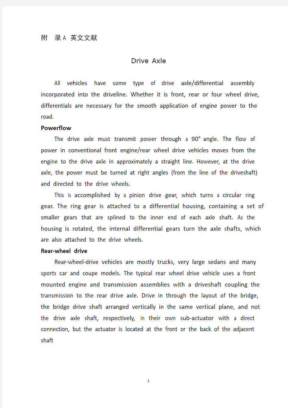
Rear-wheel-drive vehicles are mostly trucks, very large sedans and many sports car and coupe models. The typical rear wheel drive vehicle uses a front mounted engine and transmission assemblies with a driveshaft coupling the transmission to the rear drive axle. Drive in through the layout of the bridge, the bridge drive shaft arranged vertically in the same vertical plane, and not the drive axle shaft, respectively, in their own sub-actuator with a direct connection, but the actuator is located at the front or the back of the adjacent shaft
of the two bridges is arranged in series. Vehicle before and after the two ends of the driving force of the drive axle, is the sub-actuator and the transmission through the middle of the bridge. The advantage is not only a reduction of the number of drive shaft, and raise the driving axle of the common parts of each other, and to simplify the structure, reduces the volume and quality.
Fig 2 Rear-wheel-drive axle Some vehicles do not follow this typical example. Such as the older Porsche or Volkswagen vehicles which were rear engine, rear drive. These vehicles use a rear mounted transaxle with halfshafts connected to the drive wheels. Also, some vehicles were produced with a front engine, rear transaxle setup with a driveshaft connecting the engine to the transaxle, and halfshafts linking the transaxle to the drive wheels.
Differential operation
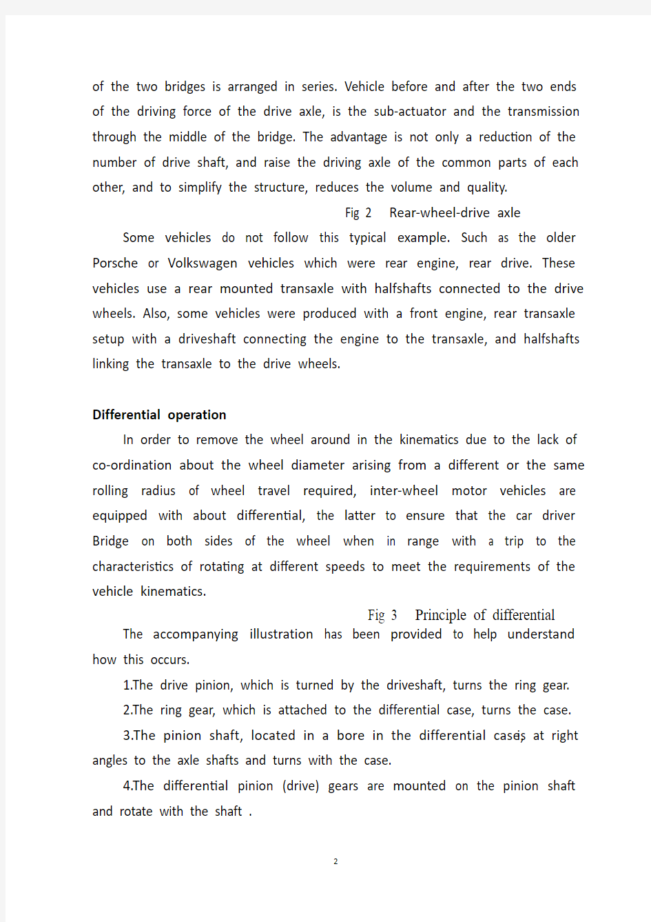
In order to remove the wheel around in the kinematics due to the lack of co-ordination about the wheel diameter arising from a different or the same rolling radius of wheel travel required, inter-wheel motor vehicles are equipped with about differential, the latter to ensure that the car driver Bridge on both sides of the wheel when in range with a trip to the characteristics of rotating at different speeds to meet the requirements of the vehicle kinematics.
Fig 3 Principle of differential The accompanying illustration has been provided to help understand how this occurs.
1.The drive pinion, which is turned by the driveshaft, turns the ring gear.
2.The ring gear, which is attached to the differential case, turns the case.
3.The pinion shaft, located in a bore in the differential case, is at right angles to the axle shafts and turns with the case.
4.The differential pinion (drive) gears are mounted on the pinion shaft and rotate with the shaft .
5.Differential side gears (driven gears) are meshed with the pinion gears and turn with the differential housing and ring gear as a unit.
6.The side gears are splined to the inner ends of the axle shafts and rotate the shafts as the housing turns.
7.When both wheels have equal traction, the pinion gears do not rotate on the pinion shaft, since the input force of the pinion gears is divided equally between the two side gears.
8.When it is necessary to turn a corner, the differential gearing becomes effective and allows the axle shafts to rotate at different speeds .
Open-wheel differential on each general use the same amount of torque. To determine the size of the wheel torque to bear two factors: equipment and friction. In dry conditions, when a lot of friction, the wheel bearing torque by engine size and gear restrictions are hours in the friction (such as driving on ice), is restricted to a maximum torque, so that vehicles will not spin round. So even if the car can produce more torque, but also need to have sufficient traction to transfer torque to the ground. If you increase the throttle after the wheels slip, it will only make the wheels spin faster.
Fig 4 Conventional differential
Limited-slip and locking differential operation
Fig 5 Limited-slip differential Differential settlement of a car in the uneven road surface and steering wheel-driven speed at about the different requirements; but is followed by the existence of differential in the side car wheel skid can not be effective when the power transmission, that is, the wheel slip can not produce the driving force, rather than spin the wheel and does not have enough torque. Good non-slip differential settlement of the car wheels skid on the side of the power transmission when the issue, that is, locking differential, so that no longer serve a useful differential right and left sides of the wheel can be the
same torque.
Limited-slip and locking differential operation can be divided into two major categories:
(1) mandatory locking type in ordinary differential locking enforcement agencies to increase, when the side of the wheel skid occurs, the driver can be electric, pneumatic or mechanical means to manipulate the locking body meshing sets of DIP Shell will be with the axle differential lock into one, thus the temporary loss of differential role. Relatively simple structure in this way, but it must be operated by the driver, and good roads to stop locking and restore the role of differential.
(2) self-locking differential installed in the oil viscosity or friction clutch coupling, when the side of the wheel skid occurs when both sides of the axle speed difference there, coupling or clutch friction resistance on the automatic, to make certain the other side of the wheel drive torque and the car continued to travel. When there is no speed difference on both sides of the wheel, the frictional resistance disappeared, the role of automatic restoration of differentials. More complicated structure in this way, but do not require drivers to operate. Has been increasingly applied in the car. About non-slip differential, not only used for the differential between the wheels, but also for all-wheel drive vehicle inter-axle differential/.
Gear ratio
The drive axle of a vehicle is said to have a certain axle ratio. This number (usually a whole number and a decimal fraction) is actually a comparison of the number of gear teeth on the ring gear and the pinion gear. For example, a 4.11 rear means that theoretically, there are 4.11 teeth on the ring gear for each tooth on the pinion gear or, put another way, the driveshaft must turn 4.11 times to turn the wheels once. The role of the final drive is to reduce the speed from the drive shaft, thereby increasing the torque. Lord of the reduction ratio reducer, a driving force for car performance and fuel
economy have a greater impact. In general, the more reduction ratio the greater the acceleration and climbing ability, and relatively poor fuel economy. However, if it is too large, it can not play the full power of the engine to achieve the proper speed. The main reduction ratio is more Smaller ,the speed is higher, fuel economy is better, but the acceleration and climbing ability will be poor.
附录B 文献翻译
驱动桥
所有的汽车都装有不同类型的驱动桥和差速器来驱动汽车行驶。无论是前驱汽车,后驱汽车还是四轮驱动的汽车,对于将发动机的动力转化到车轮上差速器都是不可缺少的部件。
动力的传递
驱动桥必须把发动机的动力转一个直角后传递出去,但人对于前轮驱动汽车发动机输出的转矩与主减速器是在同一直线上的,但是发动机前置的后轮驱动的汽车发动机的动力必须以正确的角度传递出去,来驱动车轮。
图中所示是齿轮驱动的过程,即由一个相对小的齿轮驱动一个大齿轮(主动齿轮和从动齿轮),从动锥齿轮和差速器壳连接在一起,在半轴的根部有一对带有内花键的半轴齿轮,半轴齿轮和半轴通过花键来连接在一起。当差速器壳旋转时,就驱动内部的半齿轮转动从而使半轴转动,将转矩传给车轮。
后驱动桥
后轮驱动的车辆大多是卡车,大型轿车和大部分跑车。典型的后轮驱动的车辆使用前置发动机和变速箱总成将转矩传输到后轮驱动桥。多驱动桥汽车中,在贯通式驱动桥的布置中,各桥的传动轴布置在同一纵向铅垂平面内,并且各驱动桥不是分别用自己的传动轴与分动器直接联接,而是位于分动器前面的或后面的各相邻两桥的传动轴,是串联布置的。汽车前后两端的驱动桥的动力,是经分动器并贯通中间桥而传递的。其优点是,不仅减少了传动轴的数量,而且提高了各驱动桥零件的相互通用性,并且简化了结构、减小了体积和质量。
一些车辆不是这个典型的例子。如老式的保时捷或大众汽车引擎在汽车后面,是后轮驱动。这些车辆使用的后方安装驱动桥与半轴来驱动车轮。另外,一些车辆是前置引擎,后桥与传动轴连接发动机来驱动车轮。
差速器
为了消除由于左右车轮在运动学上的不协调而产生左右车轮外径不同或滚动半径不相等而要求车轮行程,汽车左右驱动轮间都装有差速器,后者保证了汽车驱动桥两侧车轮在行程不等时具有以不同速度旋转的特性,从而满足了汽车行驶运动学要求。
如图所示说明了其工作情况
1.主动齿轮转动,从而驱动从动齿轮。
2.从动齿轮将转矩作用于差速器壳,使其转动。
3.位于差速器壳中的行星齿轮以适当的角度和半轴齿轮接触,并随的差速器壳转动。
4.行星齿轮(驱动齿轮)和十字轴连接,和十字轴一起转动。
5.半轴齿轮(被驱动齿轮)和行星齿轮啮合并且和从动齿轮及差速器壳作为一个整体一起转动。
6.半轴齿轮的内花键和半轴端部饿花键接在一起随着差速壳一起转动。
7.当两侧车轮转速相同时,行星齿轮和半轴齿轮无相对运动,左右齿轮力矩平均分配。
8.当汽车转弯时差速器开始起作用,是两侧的半轴以不同的转速旋转。
开式差速器对每个车轮一般使用相同量的扭矩。确定车轮承受的扭矩大小的因素有两个:设备和摩擦力。在干燥的条件下,当摩擦力很大时,车轮承受的扭矩大小受发动机和挡位的限制,在摩擦力很小时(如在冰上行驶),限制为最大扭矩,从而使车轮不会打滑。所以,即使汽车可以产生较大扭矩,也需要足够的牵引力将扭矩传输到地面。如果在车轮打滑之后加大油门,只会使车轮更快地旋转。如果曾在冰上驾驶过,您可能知
道加速的窍门:如果启动时挂在二挡或三挡而不是一挡,则由于变速器中的齿轮传动,车轮的扭矩会较小。这样更容易在不旋转车轮的情况下加速。如果其中一个驱动轮具有很好的摩擦力,而另一个却在冰上时,这是开式差速器存在的问题。
防滑差速器
差速器很好的解决了汽车在不平路面及转向时左右驱动车轮转速不同的要求;但随之而来的是差速器的存在使得汽车在一侧驱动轮打滑时动力无法有效传输,也就是打滑的车轮不能产生驱动力,而不打滑的车轮又没有得到足够的扭矩。防滑差速器很好的解决了汽车在一侧车轮打滑时出现的动力传输的问题,也就是锁止差速器,让差速器不再起作用,左右两侧的驱动轮均可得到相同的扭矩。
防滑差速器主要可分为两大类:
(1)强制锁止式在普通差速器上增加强制锁止机构,当发生一侧车轮打滑时,驾驶员可通过电动、气动或机械的方式来操纵锁止机构,拨动啮合套将差速器壳与半轴锁成一体,从而暂时失去差速的作用。这种方式结构比较简单,但必须由驾驶员进行操作,并在良好路面上停止锁止,恢复差速器的作用。
(2)自锁式在差速器中安装粘性硅油联轴节或摩擦离合器,当发生一侧车轮打滑时,两侧半轴出现转速差,联轴节或离合器就自动发生摩擦阻力,使另一侧车轮得到一定的扭矩而驱动汽车继续行驶。当两侧车轮没有转速差时,摩擦阻力消失,自动恢复差速器的作用。这种方式结构比较复杂,但不需要驾驶员进行操作。目前已越来越多地在汽车上得到应用。防滑差速器不仅用于左右车轮间的差速器,也用于全轮驱动汽车的轴间差速器中。
主减速比
驱动桥都有一定得主减速比,这个数字(通常是一个整数和一个小数)实际上是主减速器主动齿轮与从动齿轮的关系。例如,如果主减速比为
4.11则说明从动齿轮的齿数是主动齿轮齿数的4.11倍,换句话说就是主动齿轮轴转动4圈车轮才转动1圈。
主减速器的作用是降低从传动轴传来的转速,从而增大扭矩。主减速器的减速比,对汽车的动力性能和燃料经济性有较大的影响。一般来说,主减速比越大,加速性能和爬坡能力较强,而燃料经济性比较差。但如果过大,则不能发挥发动机的全部功率而达到应有的车速。主减速比越小,燃料经济性较好,但加速性和爬坡能力较差。
桥梁工程毕业设计外文翻译箱梁
桥梁工程毕业设计外文翻译箱梁
西南交通大学本科毕业设计(论文) 外文资料翻译 年级: 学号: 姓名: 专业: 指导老师:
6 月
外文资料原文: 13 Box girders 13.1 General The box girder is the most ?exible bridge deck form. It can cover a range of spans from25 m up to the largest non-suspended concrete decks built, of the order of 300 m. Single box girders may also carry decks up to 30 m wide. For the longer span beams, beyond about 50 m, they are practically the only feasible deck section. For the shorter spans they are in competition with most of the other deck types discussed in this book. The advantages of the box form are principally its high structural ef?ciency (5.4), which minimises the prestress force required to resist a given bending moment, and its great torsional strength with the capacity this gives to re-centre eccentric live loads, minimising the prestress required to carry them.
解放CA1092货车双级主减速器驱动桥毕业设计
摘要 本次设计的题目是中型货车驱动桥设计。驱动桥一般由主减速器、差速器、半轴及桥壳四部分组成,其基本功用是增大由传动轴或直接由变速器传来的转矩,将转矩分配给左、右车轮,并使左、右驱动车轮具有汽车行驶运动学所要求的差速功能;此外,还要承受作用于路面和车架或车厢之间的铅垂力、纵向力和横向力。 本文首先论述了驱动桥的总体结构,在分析驱动桥各部分结构型式、发展过程,及其以往形式的优缺点的基础上,确定了总体设计方案:采用整体式驱动桥,主减速器的减速型式采用双级减速器,主减速器齿轮采用螺旋锥齿轮,差速器采用普通对称式圆锥行星齿轮差速器,半轴型式采用全浮式,桥壳采用铸造整体式桥壳。在本次设计中,主要完成了双级减速器、圆锥行星齿轮差速器、全浮式半轴、桥壳的设计工作。 关键词:驱动桥;主减速器;全浮式半轴;桥壳;差速器
目录 摘要............................................................................................ ................ (2) 第1章绪论 (4) 1.1 课题研究的目的和意义 (4) 1.2 课题研究现状 (4) 1.2.1主减速器型式及其现状 (5) 1.2.差速器形式发展现状............................................................................................................. .4 1.2.半轴形式发展现状............................................................ .................. . (5) 1.2.桥壳形式发展现状......................................................... .................. . (5) 1.3 设计主要内容 (9) 第2章设计方案的确定 (7) 2.1 基本参数的选择 (7) 2.2 主减速比的计算 (7) 2.3 主减速器结构方案的确定 (8) 2.4差速器的选择 (8) 2.5半轴型式的确定 (9) 2.6桥壳型式的确定 (9) 2.7本章小结 (9) 第3章主减速器的基本参数选择与设计计算 (13) 3.1 主减速齿轮计算载荷的计算 (13) 3.2 主减速器齿轮参数的选择 (14) 3.3 主减速器螺旋锥齿轮的几何尺寸计算与强度计算 (15) 3.3.1 主减速器螺旋锥齿轮的几何尺寸计算 (15) 3.3.2 主减速器螺旋锥齿轮的强度计算 (16) 3.4 主减速器齿轮的材料及热处理 (19) 3.5 第二级斜齿圆柱齿轮基本参数的选择 (19) 3.6 第二级斜齿圆柱齿轮校核 (21) 3.7 主减速器轴承的计算 (19) 3.8 主减速器的润滑 (22) 3.9 本章小结 (26) 第4章差速器设计 (27) 4.1 差速器的作用 (27) 4.2 对称式圆锥行星齿轮差速器 (27) 4.2.1 差速器齿轮的基本参数选择 (28)
机械专业毕业论文外文翻译
附录一英文科技文献翻译 英文原文: Experimental investigation of laser surface textured parallel thrust bearings Performance enhancements by laser surface texturing (LST) of parallel-thrust bearings is experimentally investigated. Test results are compared with a theoretical model and good correlation is found over the relevant operating conditions. A compari- son of the performance of unidirectional and bi-directional partial-LST bearings with that of a baseline, untextured bearing is presented showing the bene?ts of LST in terms of increased clearance and reduced friction. KEY WORDS: ?uid ?lm bearings, slider bearings, surface texturing 1. Introduction The classical theory of hydrodynamic lubrication yields linear (Couette) velocity distribution with zero pressure gradients between smooth parallel surfaces under steady-state sliding. This results in an unstable hydrodynamic ?lm that would collapse under any external force acting normal to the surfaces. However, experience shows that stable lubricating ?lms can develop between parallel sliding surfaces, generally because of some mechanism that relaxes one or more of the assumptions of the classical theory. A stable ?uid ?lm with su?cient load-carrying capacity in parallel sliding surfaces can be obtained, for example, with macro or micro surface structure of di?erent types. These include waviness [1] and protruding microasperities [2–4]. A good literature review on the subject can be found in Ref. [5]. More recently, laser surface texturing (LST) [6–8], as well as inlet roughening by longitudinal or transverse grooves [9] were suggested to provide load capacity in parallel sliding. The inlet roughness concept of Tonder [9] is based on ??e?ective clearance‘‘ reduction in the sliding direction and in this respect it is identical to the par- tial-LST concept described in ref. [10] for generating hydrostatic e?ect in high-pressure mechanical seals. Very recently Wang et al. [11] demonstrated experimentally a doubling of the load-carrying capacity for the surface- texture design by reactive ion etching of SiC
驱动桥外文翻译
驱动桥设计 随着汽车对安全、节能、环保的不断重视,汽车后桥作为整车的一个关键部件,其产品的质量对整车的安全使用及整车性能的影响是非常大的,因而对汽车后桥进行有效的优化设计计算是非常必要的。 驱动桥处于动力传动系的末端,其基本功能是增大由传动轴或变速器传来的转矩,并将动力合理地分配给左、右驱动轮,另外还承受作用于路面和车架或车身之间的垂直力力和横向力。驱动桥一般由主减速器、差速器、车轮传动装置和驱动桥壳等组成。 驱动桥作为汽车四大总成之一,它的性能的好坏直接影响整车性能,而对于载重汽车显得尤为重要。驱动桥设计应当满足如下基本要求: 1、符合现代汽车设计的一般理论。 2、外形尺寸要小,保证有必要的离地间隙。 3、合适的主减速比,以保证汽车的动力性和燃料经济性。 4、在各种转速和载荷下具有高的传动效率。 5、在保证足够的强度、刚度条件下,力求质量小,结构简单,加工工艺性 好,制造容易,拆装,调整方便。 6、与悬架导向机构运动协调,对于转向驱动桥,还应与转向机构运动协调。智能电子技术在汽车上得以推广使得汽车在安全行驶和其它功能更上一层楼。通过各种传感器实现自动驾驶。除些之外智能汽车装备有多种传感器能充分感知交通设施及环境的信息并能随时判断车辆及驾驶员是否处于危险之中,具备自主寻路、导航、避撞、不停车收费等功能。有效提高运输过程中的安全,减少驾驶员的操纵疲劳度,提高乘客的舒适度。当然蓄电池是电动汽车的关键,电动汽车用的蓄电池主要有:铅酸蓄电池、镍镉蓄电池、钠硫蓄电池、钠硫蓄电池、锂电池、锌—空气电池、飞轮电池、燃料电池和太阳能电池等。在诸多种电池中,燃料电池是迄今为止最有希望解决汽车能源短缺问题的动力源。燃料电池具有高效无污染的特性,不同于其他蓄电池,其不需要充电,只要外部不断地供给燃料,就能连续稳定地发电。燃料电池汽车(FCEV)具有可与内燃机汽车媲美的动力性能,在排放、燃油经济性方面明显优于内燃机车辆。
机械毕业设计英文外文翻译399驱动桥
附录A 英文文献 Drive Axle All vehicles have some type of drive axle/differential assembly incorporated into the driveline. Whether it is front, rear or four wheel drive, differentials are necessary for the smooth application of engine power to the road. Powerflow The drive axle must transmit power through a 90°angle. The flow of power in conventional front engine/rear wheel drive vehicles moves from the engine to the drive axle in approximately a straight line. However, at the drive axle, the power must be turned at right angles (from the line of the driveshaft) and directed to the drive wheels. This is accomplished by a pinion drive gear, which turns a circular ring gear. The ring gear is attached to a differential housing, containing a set of smaller gears that are splined to the inner end of each axle shaft. As the housing is rotated, the internal differential gears turn the axle shafts, which are also attached to the drive wheels. Rear-wheel drive Rear-wheel-drive vehicles are mostly trucks, very large sedans and many sports car and coupe models. The typical rear wheel drive vehicle uses a front mounted engine and transmission assemblies with a driveshaft coupling the transmission to the rear drive axle. Drive in through the layout of the bridge, the bridge drive shaft arranged vertically in the same vertical plane, and not the drive axle shaft, respectively, in their own sub-actuator with a direct connection, but the actuator is located at the front or the back of the adjacent shaft
机械类毕业设计外文翻译
本科毕业论文(设计) 外文翻译 学院:机电工程学院 专业:机械工程及自动化 姓名:高峰 指导教师:李延胜 2011年05 月10日 教育部办公厅 Failure Analysis,Dimensional Determination And
Analysis,Applications Of Cams INTRODUCTION It is absolutely essential that a design engineer know how and why parts fail so that reliable machines that require minimum maintenance can be designed.Sometimes a failure can be serious,such as when a tire blows out on an automobile traveling at high speed.On the other hand,a failure may be no more than a nuisance.An example is the loosening of the radiator hose in an automobile cooling system.The consequence of this latter failure is usually the loss of some radiator coolant,a condition that is readily detected and corrected.The type of load a part absorbs is just as significant as the magnitude.Generally speaking,dynamic loads with direction reversals cause greater difficulty than static loads,and therefore,fatigue strength must be considered.Another concern is whether the material is ductile or brittle.For example,brittle materials are considered to be unacceptable where fatigue is involved. Many people mistakingly interpret the word failure to mean the actual breakage of a part.However,a design engineer must consider a broader understanding of what appreciable deformation occurs.A ductile material,however will deform a large amount prior to rupture.Excessive deformation,without fracture,may cause a machine to fail because the deformed part interferes with a moving second part.Therefore,a part fails(even if it has not physically broken)whenever it no longer fulfills its required function.Sometimes failure may be due to abnormal friction or vibration between two mating parts.Failure also may be due to a phenomenon called creep,which is the plastic flow of a material under load at elevated temperatures.In addition,the actual shape of a part may be responsible for failure.For example,stress concentrations due to sudden changes in contour must be taken into account.Evaluation of stress considerations is especially important when there are dynamic loads with direction reversals and the material is not very ductile. In general,the design engineer must consider all possible modes of failure,which include the following. ——Stress ——Deformation ——Wear ——Corrosion ——Vibration ——Environmental damage ——Loosening of fastening devices
驱动桥5000字外文翻译文献
As the bearing cage rotates, read the value 7. indicated on the scale. Preload normally is specified as torque re-8. quired to rotate the pinion bearing cage, so take a reading only when the cage is rotating. Starting torque will give a false reading. To calculate the preload torque, measure the 9. diameter of the bearing cage where the cord was wound. Divide this dimension in half to get the radius. 10. U se the following procedure to calculate the bearing preload torque:Standard. Pull (lb) 3 radius (inches) 5 preload (lb-in.)or Preload (lb-in.) 3 0.113 (a conversion constant) 5 preload (N .m) Install the yoke, flat washer, and nut. Tighten 6. the nut snugly. Tap the end of the input shaft lightly to seat the bearings. Measure the input shaft endplay again with 7. the dial indicator. If endplay is still incorrect, repeat steps 3 through 7. With the endplay correct, seal the shim pack 8. to prevent lube leakage. Then torque the i nput shaft nut and cover capscrews to the correct value. 24.5 A XLE ADJUSTMENTS AND CHECKS This section introduces the differential carrier adjust-ments, checks, and tests that the truck technician must be capable of performing; some have been r eferred to previously in the text. For the most part, the procedures described here are general in nature. The truck technician should refer to OEM service l iterature for specific procedures.PINION BEARING PRELOAD Most differential carriers are provided with a press-fit outer bearing on the drive pinion gear. Some older rear drive axles use an outer bearing, which slips over the drive pinion. The procedures for adjusting both types follow. Press-Fit Method Adjustment To adjust the pinion bearing preload using the press-fit method, use the following procedure: Assemble the pinion bearing cage, bearings, 1. spacer, and spacer washer (without drive pin-ion or oil seal). Center the bearing spacer and spacer washer between the two bearing cones (Figure 24–49). When a new gear set or pinion bearings are 2. used, select a nominal size spacer based on OEM specifications. If original parts are used, use a spacer removed during disassembly of the drive. Place the drive pinion and cage assembly in a 3. press, with the gear teeth toward the bottom.Apply and hold the press load to the pinion 4. bearing. As pressure is applied, rotate the bearing cage several times so that the bear-ings make normal contact. While pressure is held against the assembly, wind 5. a cord around the bearing cage several times.Attach a spring scale to the end of the cord 6. (Figure 24–50). Pull the cord with the scale on a horizontal line. FIGURE 24–49 Assembly of the pinion bearing cage. (Courtesy of Dana Corporation) FIGURE 24–50 Cage in press to check bearing p reload. Sleeve must apply
汽车车辆类驱动桥的设计外文文献翻译、外文翻译、中英文翻译
附录I Drive axle powertrain at the end of their basic function is to increase the transmission came from the drive shaft or torque, and a reasonable distribution of power to the left and right wheel, in addition to acting on the road and under the frame or body legislation between the vertical, longitudinal and lateral force. General from the main drive axle reducer, differential, gear wheels and drive axle housings and other components. The design of the Drive axle: Drive axle should be designed to meet the basic requirements are as follows: 1. Select the main reduction ratio should be able to ensure the car has the best power and fuel economy. 2. Smaller size, to ensure that the necessary ground clearance. 3. Gear and other pieces of the work of a smooth transmission,and small noise. 4. In a variety of speed and load with a high transmission efficiency. 5. In ensuring adequate strength and stiffness conditions, should strive for the quality of small, especially under the mass-spring should be as small as possible in order to improve vehicle ride comfort. 6. And suspension movement-oriented coordination of steering drive axle, but also with the coordination of steering movement. 7. The structure of simple, good processing, manufacturing, easy disassembly, to facilitate adjustment. Drive axle classification -1-
车辆工程毕业设计14CA1040轻型货车驱动桥设计
本科学生毕业设计 CA1040轻型货车驱动桥设计 学院名称:汽车与交通工程学院 专业班级:车辆工程 学生姓名: 指导教师: 职称:实验师
摘要 驱动桥位于传动系末端,其基本功用是增矩、降速,承受作用于路面和车架或车身之间的作用力。它的性能好坏直接影响整车性能,而对于载重汽车显得尤为重要。轻型货车在商用货运汽车生产中占有很大的比重,为满足目前当前载货汽车的高速度、高效率、高效益的需要,必须要搭配一个高效、可靠的驱动桥。因此设计出结构简单、工作可靠、造价低廉的驱动桥,能大大降低整车生产的总成本,推动汽车经济的发展,并且通过对汽车驱动桥的学习和设计实践,可以更好的学习并掌握现代汽车设计与机械设计的全面知识和技能,所以本课题设计一款结构优良的轻型货车驱动桥具有一定的实际意义。 驱动桥设计应主要保证汽车在给定的条件下具有最佳的动力性和燃油经济性。本设计根据给定的参数,按照传统设计方法并参考同类型车确定汽车总体参数,再确定主减速器、差速器、半轴和桥壳的结构类型,最后进行参数设计并对主减速器主、从动齿轮、半轴齿轮和行星齿轮进行强度以及寿命的校核。驱动桥设计过程中基本保证结构合理,符合实际应用,总成及零部件的设计能尽量满足零件的标准化、部件的通用化和产品的系列化及汽车变型的要求,修理、保养方便,机件工艺性好,制造容易。 关键词:驱动桥;单级主减速器;差速器;半轴;桥壳
ABSTRACT Drive axle is at the end of the power train, and its basic function is increasing the torque and reducing the speed, bearing the force between the road and the frame or body. Its performance will have a direct impact on automobile performance .Because using the big power engine with the big driving torque satisfied the need of high speed,heavy-loaded,high efficiency,high benefit today’ heavy truck,must exploiting the high driven efficiency single reduction final drive axle is becoming the heavy truck’ developing tendency. Because using the big power engine with the big driving torque satisfied the need of high speed, heavy-loaded, high efficiency, high benefit today` truck, must exploiting the high driven efficiency single reduction final drive axle is becoming the trucks’ developing tendency. Design a simple, reliable, low cost of the drive axle, can greatly reduce the total cost of vehicle production, and promote the economic development of automobile and automotive drive axle of the study and design practice, can better learn and to master modern automotive design and mechanical design of a comprehensive knowledge and skills, so the title of the fine structure of the design of a pickup vehicle drive axle has a certain practical significance. According to the design parameters given ,firstly determine the overall vehicle parameters in accordance with the traditional design methods and reference the same vehicle parameters, then identify the main reducer, differential, axle and axle housing structure type, finally design the parameters of the main gear, the driven gear of the final drive, axle gears and spiral bevel gear and check the strength and life of them. In design process of the drive axle, we should ensure a reasonable structure, practical applications, the design of assembly and parts as much as possible meeting requirements of the standardization of parts, components and products’ universality and the serialization and change , convenience of repair and maintenance, good mechanical technology, being easy to manufacture. Key words: Drive axle; Single reduction final drive; Differential; Axle; Drive Axle housing
机械类毕业设计外文文献翻译
沈阳工业大学工程学院 毕业设计(论文)外文翻译 毕业设计(论文)题目:工具盒盖注塑模具设计 外文题目:Friction , Lubrication of Bearing 译文题目:轴承的摩擦与润滑 系(部):机械系 专业班级:机械设计制造及其自动化0801 学生姓名:王宝帅 指导教师:魏晓波 2010年10 月15 日
外文文献原文: Friction , Lubrication of Bearing In many of the problem thus far , the student has been asked to disregard or neglect friction . Actually , friction is present to some degree whenever two parts are in contact and move on each other. The term friction refers to the resistance of two or more parts to movement. Friction is harmful or valuable depending upon where it occurs. friction is necessary for fastening devices such as screws and rivets which depend upon friction to hold the fastener and the parts together. Belt drivers, brakes, and tires are additional applications where friction is necessary. The friction of moving parts in a machine is harmful because it reduces the mechanical advantage of the device. The heat produced by friction is lost energy because no work takes place. Also , greater power is required to overcome the increased friction. Heat is destructive in that it causes expansion. Expansion may cause a bearing or sliding surface to fit tighter. If a great enough pressure builds up because made from low temperature materials may melt. There are three types of friction which must be overcome in moving parts: (1)starting, (2)sliding, and(3)rolling. Starting friction is the friction between two solids that tend to resist movement. When two parts are at a state of rest, the surface irregularities of both parts tend to interlock and form a wedging action. To produce motion in these parts, the wedge-shaped peaks and valleys of the stationary surfaces must be made to slide out and over each other. The rougher the two surfaces, the greater is starting friction resulting from their movement . Since there is usually no fixed pattern between the peaks and valleys of two mating parts, the irregularities do not interlock once the parts are in motion but slide over each other. The friction of the two surfaces is known as sliding friction. As shown in figure ,starting friction is always greater than sliding friction . Rolling friction occurs when roller devces are subjected to tremendous stress which cause the parts to change shape or deform. Under these conditions, the material in front of a roller tends to pile up and forces the object to roll slightly uphill. This changing of shape , known as deformation, causes a movement of molecules. As a result ,heat is produced from the added energy required to keep the parts turning and overcome friction. The friction caused by the wedging action of surface irregularities can be overcome