中英文文献翻译-螺杆压缩机

英文原文
Screw Compressor
The Symmetric profile has a huge blow-hole area which excludes it from any compressor applicat -ion where a high or even moderate pressure ratio is involved. However, the symmetric profile per -forms surprisingly well in low pressure compressor applications.More details about the circular p -rofile can be found in Margolis, 1978.
2.4.8 SRM “A” Profile
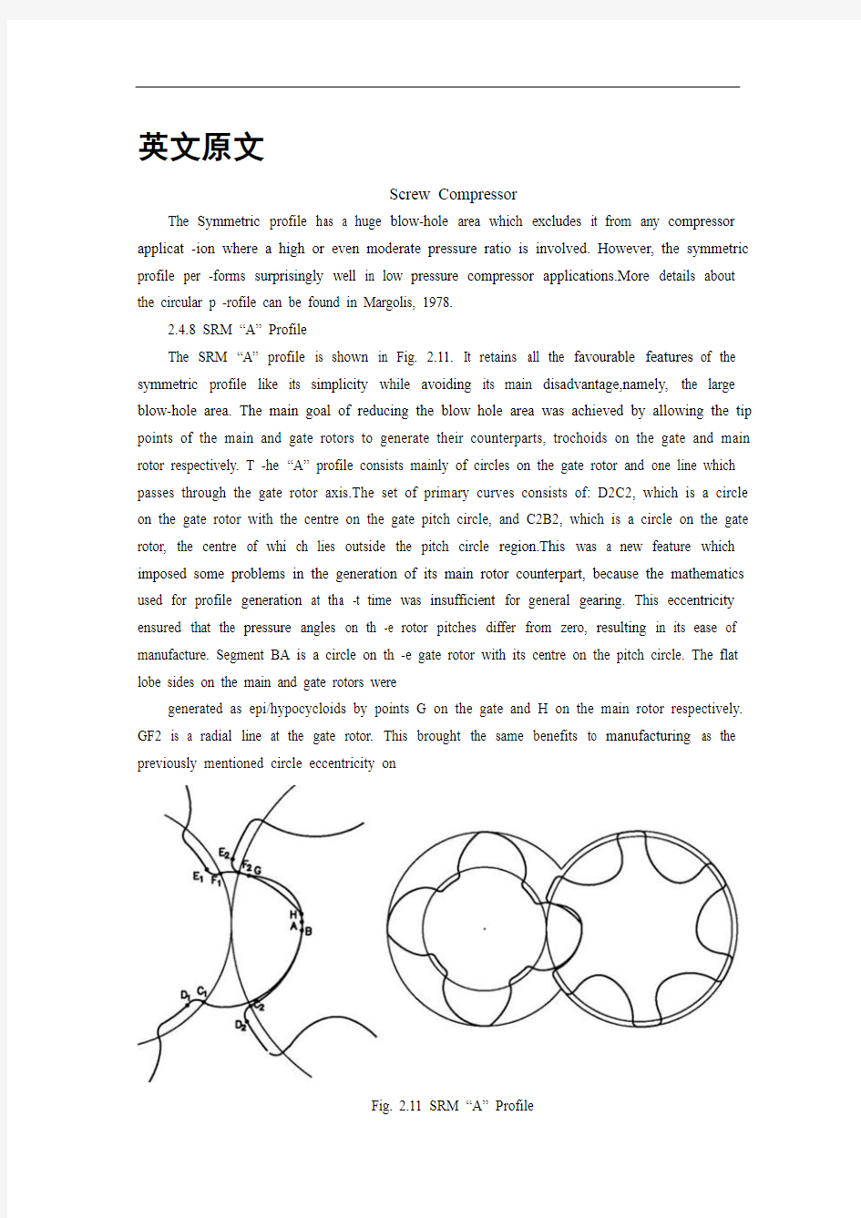
The SRM “A” profile is shown in Fig. 2.11. It retains all the favourable features of the symmetric profile like its simplicity while avoiding its main disadvantage,namely, the large blow-hole area. The main goal of reducing the blow hole area was achieved by allowing the tip points of the main and gate rotors to generate their counterparts, trochoids on the gate and main rotor respectively. T -he “A” profile consists mainly of circles on the gate rotor and one line which passes through the gate rotor axis.The set of primary curves consists of: D2C2, which is a circle on the gate rotor with the centre on the gate pitch circle, and C2B2, which is a circle on the gate rotor, the centre of whi ch lies outside the pitch circle region.This was a new feature which imposed some problems in the generation of its main rotor counterpart, because the mathematics used for profile generation at tha -t time was insufficient for general gearing. This eccentricity ensured that the pressure angles on th -e rotor pitches differ from zero, resulting in its ease of manufacture. Segment BA is a circle on th -e gate rotor with its centre on the pitch circle. The flat lobe sides on the main and gate rotors were
generated as epi/hypocycloids by points G on the gate and H on the main rotor respectively. GF2 is a radial line at the gate rotor. This brought the same benefits to manufacturing as the previously mentioned circle eccentricity on
Fig. 2.11 SRM “A” Profile
2.4 Review of Most Popular Rotor Profiles 31 the opposite lobe side. F2E2 is a circle with the cent -re on the gate pitch and finally, E2D2 is a circle with the centre on the gate axis.More details on t -he “A” profile are published by Amosov et al., 1977 and by Rinder, 1979.The “A” profile is a go od example of how a good and simple idea evolved into a complicated result. Thus the “A” pro file was continuously subjected to changes which resulted in the “C” profile. This was mainly gen erated to improve the profile manufacturability. Finally, a completely new profile, the“D” profile was generated to introduce a new development in profile gearing and to increase the gate rotor tor -que.Despite the complexity o f its final form the “A” profile emerged to be the most popular scre -w compressor profile, especially after its patent expired.
2.4.9 SRM “D” Profile
The SRM “D” profile, shown in Fig. 2.12, is generated exclusively by circles with the centres off the rotor pitch circles.
Similar to the Demonstrator, C2D2 is an eccentric circle of radius r3 onthe gate rotor. B1C1 is an eccentric circle of radius r1, which, together withthe small circular arc A1J1 of radius r2, is positioned on the main rotor. G2H2is a small circular arc on the gate rotor and E2F2 is a circular arc on the gaterotor. F2G2 is a relatively large circular arc on the gate rotor which produces a corresponding curve of the smallest possible curvature on the main rotor.Both circular arc, B2C2 and F2G2 ensure a large radius of curvature in the pitch circle area. This avoids high stresses in the rotor contact region.
Fig. 2.12 SRM “D” Profile
The “G” profile was introduced by SRM in the late nineteen nineties as a replacement for the “D” rotor and is shown in Fig. 2.13. Compared with the“D” rotor, the “G” rotor has the unique feature of two additional circles in the addendum area on both lobes of the main rotor, close to the pitch circle.This feature improves the rotor contact and, additionally, generates shorter sealing lines. This can be seen in Fig. 2.13, where a rotor featuring “G” profile characteristics only on its flat side through segment H1I1 is presented.
Fig. 2.13 SRM “G” Profile
2.4.11 City “N” Rack Generated Rotor Profile“N” rotors are calculated by a rack generation procedure. This distinguishes them from any others. In this case, the large blow-hole area, which is a characteristic of rack generated rotors, is overcome by generating the high pressure side of the rack by means of a rotor conjugate procedure. This undercuts the single appropriate curve on the rack. Such a rack is then used for profiling both the main and the gate rotors. The method and its extensions were used by the authors to create a number of different rotor profiles, some of them used by Stosic et al., 1986, and Hanjalic and Stosic, 1994. One of the applications of the rack generation procedure is described in Stosic, 1996.The following is a brief description of a rack generated “N” rotor profile,typical of a family of rotor profiles designed for the efficient compression of air,common refrigerants and a number of process gases. The rotors are generated by the combined rack-rotor generation procedure whose features are such that it may be readily modified further to optimize performance for any specific application.
2.4 Review of Most Popular Rotor Profiles 33
The coordinates of all primary arcs on the rack are summarized here relative to the rack coordinate system. The lobe of the rack is divided into several arcs. The divisions between the profile arcs are denoted by capital letters and each arc is defined separately, as shown in the Figs.
2.14 and 2.15 where the rack and the rotors are shown.
Fig. 2.14 Rack generated “N” Profile
Fig. 2.15 “N” rotor primary curves g iven on rack
34 2 Screw Compressor Geometry
All curves are given as a “general arc” expressed as: axp + byq = 1. Thus straight lines, circles, parabolae, ellipses and hyperbolae are all easily described by selecting appropriate values for parameters a, b, p and q.Segment DE is a straight line on the rack, EF is a circular arc of radius r4,
segment FG is a straight line for the upper involute, p = q = 1, while segment GH on the rack is a meshing curve generated by the circular arc G2H2 on the gate rotor. Segment HJ on the rack is a meshing curve generated by the circular arc H1J1 of radius r2 on the main rotor. Segment JA is a circular arc of radius r on the rack, AB is an arc which can be either a circle or a parabola, a hyperbola or an ellipse, segment BC is a straight line on the rack matching the involute on the rotor round lobe and CD is a circular arc on the rack, radius r3.More details of the “N” profile can be found in Stosic, 1994.
2.4.12 Characteristics of “N” Profile
Sample illustrations of the “N” profile in 2-3, 3-5, 4-5, 4-6, 5-6, 5-7 and 6-7 configurations are given in Figs. 2.16 to Fig. 2.23. It should be noted that all rotors considered were obtained automatically from a computer code by simply specifying the number of lobes in the main and gate rotors, and the lobe curves in the general form.A variety of modified profiles is possible. The “N” profile design is a compromise between full tightness, small blow-hole area, large displacement.
Fig. 2.16 “N” Rotors in 2-3 configuration
Fig. 2.17 “N” Rotors in 3-5 configuration
Fig. 2.18 “N” Rotors in 4-5 configuration
Fig. 2.19 “N” Rotors in 4-6 configuration
Fig. 2.20 “N” Rotors compared with “Sigma”, SRM “D” and “Cyclon” rotors
Fig. 2.21 “N” Rotors in 5-6 configuration
Fig. 2.22 “N” Rotors in 5-7 configuration
Fig. 2.23 “N” rotors in 6/7 configuration
sealing lines, small confined volumes, involute rotor contact and proper gate rotor torque distribution together with high rotor mechanical rigidity.The number of lobes required varies according to the designated compressor duty. The 3/5 arrangement is most suited for dry air compression, the 4/5 and 5/6 for oil flooded compressors with a moderate pressure difference and the 6/7 for high pressure and large built-in volume ratio refrigeration applications.Although the full evaluation of a rotor profile requires more than just a geometric assessment, some of the key features of the “N” profile may be readily appreciated by comparing it with three of the most popular screw rotor profiles already described here, (a) The “Sigma” profile by Bammert,1979, (b) the SRM “D” profile by Astberg 1982, and (c) the “Cyclon” profile by Hough and Morris, 1984. All these rotors are shown in Fig. 2.20 where it can be seen that the “N” profiles have a grea ter throughput and a stiffer gate rotor for all cases when other characteristics such as the blow-hole area, confined volume and high pressure sealing line lengths are identical.Also, the low pressure sealing lines are shorter, but this is less important because the corresponding clearance can be kept small.The blow-hole area may be controlled by adjustment of the tip radii on both the main and gate rotors and also by making the gate outer diameter equal to or less than the pitch diameter. Also the sealing lines can be kept very short by constructing most of the rotor profile from circles whose centres are close to the pitch circle. But, any decrease in the blow-hole area will increase
the length of the sealing line on the flat rotor side. A compromise betweenthese trends is therefore required to obtain the best result.
2.4 Review of Most Popular Rotor Profiles 39
Rotor instability is often caused by the torque distribution in the gate rotor changing direction during a complete cycle. The profile generation procedure described in this paper makes it
possible to control the torque on the gate rotor and thus avoid such effects. Furthermore, full involute contact between the “N” rotors enables any additional contact load to be absorbed more easily than with any other type of rotor. Two rotor pairs are shown in Fig. 2.24 the first exhibits what is described as “negative” gate rotor torque while the second shows the more usual “positive” torque.
Fig. 2.24 “N” with negative torque, left and positive torque, right
2.4.13 Blower Rotor Profile
The blower profile, shown in Fig. 2.25 is symmetrical. Therefore only one quarter of it needs to be specified in order to define the whole rotor. It consists of two segments, a very small circle on the rotor lobe tip and a straight line. The circle slides and generates cycloids, while the straight line generates involutes.
Fig. 2.25 Blower profile
中文译文
螺杆压缩机
螺杆压缩机的几何形状对称分布有一个巨大的吹孔面积不包括它任何压缩机应用在高或中等压力比参与。然而,对称分布的表现出奇的好在低高压压缩机中的应用。对圆形的轮廓,更多的细节可以发现马德克,1978。
2.4.8 SRM的“A”型
SRM”“曲线如图2.11所示。它保留了所有的有利的特征的对称外形像它的简单性的同时避免其主要的缺点,即,大吹孔面积。减少的主要目标气孔面积允许主门的尖点了转子产生他们的同行,在栅极和主转子摆线分别同行,剖面主要由界的门转子和一条线穿过门转子轴。
主曲线的设置包括:D2C2,这是一个圆形的门转子与中心门口节圆,C2B2,这是一个圆在大门口转子,该中心位于外的节圆区域。这是一个新的功能实施的一些问题在一代的主旋翼同行,因为数学用于配置生成。当时通用传动装置不足。这偏心保证压力角的转子球不同于零,导致它的易于制造。段是一个圆形的英航转子以其中心门在节圆。扁平的叶边的主要和门出现生成EPI /圆内旋轮线,分别由G和H的门主转子组成。是一个径向线GF2门口的转子。这带来了同样的制造业的好处前面提到的圆偏心在最受欢迎的转子型线的评论2.4。
图2.11 “A”型发动机
31对面的叶侧。F2E2是一个圆的中心在大门口音高和最后,E2D2是一个圆的中心在门轴。有关“A”简介的更多详细信息由Amosov et al. 所出版的,1977 年和作者:Rinder,1979。
“一个”配置文件是一个很好的例子,一个好的和简单的想法如何进成一个复杂的结果。因此,“一个”剖面是不断遭受这导致变化的“C”剖面。这主要是生成改善剖面可制造性。最后,一个完全新的配置文件“D”剖面生成了一个新的发展介绍在剖面传动装置和增加门转子
【经济类文献翻译】电子商务
电子商务 电子商务(Electronic Commerce)是在Internet开放的网络环境下,基于浏览器/服务器应用方式,实现消费者的网上购物、商户之间的网上交易和在线电子支付的一种新型的商业运营模式 Internet上的电子商务可以分为三个方面:信息服务、交易和支付。主要内容包括:电子商情广告;电子选购和交易、电子交易凭证的交换;电子支付与结算以及售后的网上服务等。主要交易类型有企业与个人的交易(BtoC方式)和企业之间的交易(BtoB方式)两种。参与电子商务的实体有四类:顾客(个人消费者或企业集团)、商户(包括销售商、制造商、储运商)、银行(包括发卡行、收单行)及认证中心。 电子商务是Internet爆炸式发展的直接产物,是网络技术应用的全新发展方向。Internet本身所具有的开放性、全球性、低成本、高效率的特点,也成为电子商务的内在特征,并使得电子商务大大超越了作为一种新的贸易形式所具有的价值,它不仅会改变企业本身的生产、经营、管理活动,而且将影响到整个社会的经济运行与结构。 1.电子商务将传统的商务流程电子化、数字化,一方面以电子流代替了实物流,可以大量减少人力、物力,降低了成本;另一方面突破了时间和空间的限制,使得交易活动可以在任何时间、任何地点进行,从而大大提高了效率。 2.电子商务所具有的开放性和全球性的特点,为企业创造了更多的贸易机会。 3.电子商务使企业可以以相近的成本进入全球电子化市场,使得中小企业有可能拥有和大企业一样的信息资源,提高了中小企业的竞争能力。 4.电子商务重新定义了传统的流通模式,减少了中间环节,使得生产者和消费者的直接交易成为可能,从而在一定程度上改变了整个社会经济运行的方式。 5.电子商务一方面破除了时空的壁垒,另一方面又提供了丰富的信息资源,
商务英语口语900句-中英文对照-中文翻译资料
商务英语口语900句中英文对照中文翻译 Unit 1希望与要求 Part 1 . 1. We'd like to express our desire to establish business relationship with you on the basis of quality, mutually benefit and exchange of needed goods . 我们希望在保证质量、互惠互利以及交易彼此需要的货物的基础上和你们建立业务关系。 2 .In order to extend our export business to your country we wish to enter direct business relations with you. 为了扩大我们在贵国的出口业务,我们希望和你们建立直接贸易关系。 3. Our hope is to establish mutually beneficial trading relations between us . 希望在我们之间能够建立互惠互利的贸易关系。 4. We looking forward to further extensions of pleasant business relations. 我们期待进一步保持愉快的业务关系。 5. It’s our hope to continue with considerable business dealing with you. 我们的希望是和你们保持可观的生意往来。 6. We looking forward to receiving your quotation very soon. 我们期待尽快收到你们的报价单。 7.I hope you see from the reduction that we are really doing our utmost. 我希望你能够看到我们事实上已经作出了最大程度的让价。 8.We hope to discuss business with you at your earliest convenience. 我们希望在你方便的时候和你洽谈业务。
中英文文献翻译
毕业设计(论文)外文参考文献及译文 英文题目Component-based Safety Computer of Railway Signal Interlocking System 中文题目模块化安全铁路信号计算机联锁系统 学院自动化与电气工程学院 专业自动控制 姓名葛彦宁 学号 200808746 指导教师贺清 2012年5月30日
Component-based Safety Computer of Railway Signal Interlocking System 1 Introduction Signal Interlocking System is the critical equipment which can guarantee traffic safety and enhance operational efficiency in railway transportation. For a long time, the core control computer adopts in interlocking system is the special customized high-grade safety computer, for example, the SIMIS of Siemens, the EI32 of Nippon Signal, and so on. Along with the rapid development of electronic technology, the customized safety computer is facing severe challenges, for instance, the high development costs, poor usability, weak expansibility and slow technology update. To overcome the flaws of the high-grade special customized computer, the U.S. Department of Defense has put forward the concept:we should adopt commercial standards to replace military norms and standards for meeting consumers’demand [1]. In the meantime, there are several explorations and practices about adopting open system architecture in avionics. The United Stated and Europe have do much research about utilizing cost-effective fault-tolerant computer to replace the dedicated computer in aerospace and other safety-critical fields. In recent years, it is gradually becoming a new trend that the utilization of standardized components in aerospace, industry, transportation and other safety-critical fields. 2 Railways signal interlocking system 2.1 Functions of signal interlocking system The basic function of signal interlocking system is to protect train safety by controlling signal equipments, such as switch points, signals and track units in a station, and it handles routes via a certain interlocking regulation. Since the birth of the railway transportation, signal interlocking system has gone through manual signal, mechanical signal, relay-based interlocking, and the modern computer-based Interlocking System. 2.2 Architecture of signal interlocking system Generally, the Interlocking System has a hierarchical structure. According to the function of equipments, the system can be divided to the function of equipments; the system
文献翻译英文原文
https://www.360docs.net/doc/2c11928890.html,/finance/company/consumer.html Consumer finance company The consumer finance division of the SG group of France has become highly active within India. They plan to offer finance for vehicles and two-wheelers to consumers, aiming to provide close to Rs. 400 billion in India in the next few years of its operations. The SG group is also dealing in stock broking, asset management, investment banking, private banking, information technology and business processing. SG group has ventured into the rapidly growing consumer credit market in India, and have plans to construct a headquarters at Kolkata. The AIG Group has been approved by the RBI to set up a non-banking finance company (NBFC). AIG seeks to introduce its consumer finance and asset management businesses in India. AIG Capital India plans to emphasize credit cards, mortgage financing, consumer durable financing and personal loans. Leading Indian and international concerns like the HSBC, Deutsche Bank, Goldman Sachs, Barclays and HDFC Bank are also waiting to be approved by the Reserve Bank of India to initiate similar operations. AIG is presently involved in insurance and financial services in more than one hundred countries. The affiliates of the AIG Group also provide retirement and asset management services all over the world. Many international companies have been looking at NBFC business because of the growing consumer finance market. Unlike foreign banks, there are no strictures on branch openings for the NBFCs. GE Consumer Finance is a section of General Electric. It is responsible for looking after the retail finance operations. GE Consumer Finance also governs the GE Capital Asia. Outside the United States, GE Consumer Finance performs its operations under the GE Money brand. GE Consumer Finance currently offers financial services in more than fifty countries. The company deals in credit cards, personal finance, mortgages and automobile solutions. It has a client base of more than 118 million customers throughout the world
中英文对照资料外文翻译文献
中英文对照资料外文翻译文献 平设计任何时期平面设计可以参照一些艺术和专业学科侧重于视觉传达和介绍。采用多种方式相结合,创造和符号,图像和语句创建一个代表性的想法和信息。平面设计师可以使用印刷,视觉艺术和排版技术产生的最终结果。平面设计常常提到的进程,其中沟通是创造和产品设计。共同使用的平面设计包括杂志,广告,产品包装和网页设计。例如,可能包括产品包装的标志或其他艺术作品,举办文字和纯粹的设计元素,如形状和颜色统一件。组成的一个最重要的特点,尤其是平面设计在使用前现有材料或不同的元素。平面设计涵盖了人类历史上诸多领域,在此漫长的历史和在相对最近爆炸视觉传达中的第20和21世纪,人们有时是模糊的区别和重叠的广告艺术,平面设计和美术。毕竟,他们有着许多相同的内容,理论,原则,做法和语言,有时同样的客人或客户。广告艺术的最终目标是出售的商品和服务。在平面设计,“其实质是使以信息,形成以思想,言论和感觉的经验”。
在唐朝(618-906 )之间的第4和第7世纪的木块被切断打印纺织品和后重现佛典。阿藏印在868是已知最早的印刷书籍。在19世纪后期欧洲,尤其是在英国,平面设计开始以独立的运动从美术中分离出来。蒙德里安称为父亲的图形设计。他是一个很好的艺术家,但是他在现代广告中利用现代电网系统在广告、印刷和网络布局网格。于1849年,在大不列颠亨利科尔成为的主要力量之一在设计教育界,该国政府通告设计在杂志设计和制造的重要性。他组织了大型的展览作为庆祝现代工业技术和维多利亚式的设计。从1892年至1896年威廉?莫里斯凯尔姆斯科特出版社出版的书籍的一些最重要的平面设计产品和工艺美术运动,并提出了一个非常赚钱的商机就是出版伟大文本论的图书并以高价出售给富人。莫里斯证明了市场的存在使平面设计在他们自己拥有的权利,并帮助开拓者从生产和美术分离设计。这历史相对论是,然而,重要的,因为它为第一次重大的反应对于十九世纪的陈旧的平面设计。莫里斯的工作,以及与其他私营新闻运动,直接影响新艺术风格和间接负责20世纪初非专业性平面设计的事态发展。谁创造了最初的“平面设计”似乎存在争议。这被归因于英国的设计师和大学教授Richard Guyatt,但另一消息来源于20世纪初美国图书设计师William Addison Dwiggins。伦敦地铁的标志设计是爱德华约翰斯顿于1916年设计的一个经典的现代而且使用了系统字体设计。在20世纪20年代,苏联的建构主义应用于“智能生产”在不同领域的生产。个性化的运动艺术在2俄罗斯大革命是没有价值的,从而走向以创造物体的功利为目的。他们设计的建筑、剧院集、海报、面料、服装、家具、徽标、菜单等。J an Tschichold 在他的1928年书中编纂了新的现代印刷原则,他后来否认他在这本书的法西斯主义哲学主张,但它仍然是非常有影响力。Tschichold ,包豪斯印刷专家如赫伯特拜耳和拉斯洛莫霍伊一纳吉,和El Lissitzky 是平面设计之父都被我们今天所知。他们首创的生产技术和文体设备,主要用于整个二十世纪。随后的几年看到平面设计在现代风格获得广泛的接受和应用。第二次世界大战结束后,美国经济的建立更需要平面设计,主要是广告和包装等。移居国外的德国包豪斯设计学院于1937年到芝加哥带来了“大规模生产”极简到美国;引发野火的“现代”
电子商务企业文化中英文对照外文翻译文献
中英文对照外文翻译文 电子商务时代企业文化的再造 随着网络时代电子商务大规模发展,电子商务企业文化随之产生,它在一个企业在产生的一种新的价值观,使企业内部资源得到从新整合,在为企业带来降低交易成本,提高效率,缩短生产周期等诸多好处的同时,也对已有的企业文化发起了挑战。电子商务的兴起是一场由技术手段飞速发展而引发的商业运作模式的变革,传统经济活动的生存基础、运作方式和管理机制均发生了彻底改变,传统的企业文化也面临着巨大的冲击。 一、企业文化对企业价值的贡献 文化现象是一个国家和民族文明的主要见证。广义的文化,包括知识、信仰、艺术、道德、法律、习俗和任何人作为一名社会成员而获得的能力和习惯在内的复杂整体。作为“亚文化”的企业文化,对企业的生存与发展亦起着举足轻重的作用。企业文化是商品经济和市场经济的产物,符合市场经济的客观规律,体现企业的竞争实务、竞争精神和整体形象。所谓企业文化就是企业的经营管理哲学,企业面对所处的社会和商业环境,在长期的生产经营活动中,形成全体员工所接受和认同信守的、为争取事业成功的一套非正式规则。它表明企业奉行何种管理哲学,以及企业通过管理要达到一个什么样的目标。是经济管理的重要内容之一。企业文化意味着一个公司的价值观,而这些价值观成为公司员工活动和行为的规范。 企业文化的本源问题是如何增加企业利润,降低企业的成本和费用。它的要义就是怎么使企业能够有效的整合资源,以达到对外部的适应性,使公司在竞争中生存,进而实现持续发展。企业文化建设为企业开展文化管理指出一个明确的方向。企业文化建设的根本目的是建设能够对外竞争环境具有高度适应性,并能根据环境变换做出迅速反应的行为方式能力,这种能力其实就是企业所拥有的根据外部竞争的环境需要而对内部资源进行整合运用的能力。企业文化建设应促进这一能力系统的形成,并维持好这一能力系统。中国的许多企业例如海尔、联想等企业成功的秘诀之一就是发展了一整套公司理念、经营哲学,形成了自己独特的企业文化。 1、企业文化体现企业的形象和精神。树立良好的企业形象,需要企业文化的支撑。现
统计学中英文对照外文翻译文献
中英文对照翻译 (文档含英文原文和中文翻译) Policies for Development of Iron and Steel Industry The iron and steel industry is an important basic industry of the national economy, a supporting industry for realizing the industrialization and an intensive industry in technologies, capital, resources and energy, and its development requires a comprehensive balancing of all kinds of external conditions. China is a big developing country with a comparatively big demand of iron and steel in the economic development for a long time to go. China's production capacity of iron and steel has ranked the first place in the world for many years. However, there is a large gap in terms of the technological level and material consumption of the iron and steel industry compared with the international advanced level, so the focus of development for the future shall be put on technical upgrading and structural adjustment. In order to enhance the whole technical level of the iron and steel industry, promote the structural adjustment, improve the industrial layout, develop a recycling economy, lower the consumption of materials and energy, pay attention to the environmental protection, raise the comprehensive competitive capacity of enterprises, realize the industrial upgrading, and develop the iron and steel industry into an industry with
材料英文文献翻译
The development of plastic mould China's industrial plastic moulds from the start to now, after more than half a century, there has been great development, mold levels have been greatly enhanced. Mould has been at large can produce 48-inch big-screen color TV Molded Case injection mold, 6.5 kg capacity washing machine full of plastic molds, as well as the overall car bumpers and dashboards, and other plastic mould precision plastic molds, the camera is capable of producing plastic mould , multi-cavity mold small modulus gear and molding mold. --Such as Tianjin and Yantai days Electrical Co., Ltd Polaris IK Co. manufactured multi-cavity mold VCD and DVD gear, the gear production of such size precision plastic parts, coaxial, beating requirements have reached a similar foreign the level of product, but also the application of the latest gear design software to correct contraction as a result of the molding profile error to the standard involute requirements. Production can only 0.08 mm thickness of a two-cavity mold and the air Cup difficulty of plastic doors and windows out of high modulus, and so on. Model cavity injection molding manufacturing accuracy of 0.02 to 0.05 mm, surface roughness Ra0.2 μ m, mold quality, and significantly increase life expectancy, non-hardening steel mould life up to 10~ 30 million, hardening steel form up to 50 ~ 10 million times, shorten the delivery time than before, but still higher than abroad,and the gap between a specific data table. Process, the multi-material plastic molding die, efficient multicolor injection mould, inserts exchange structure and core pulling Stripping the innovative design has also made great progress. Gas-assisted injection molding, the use of more mature technologies, such as Qingdao Hisense Co., Ltd., Tianjin factory communications and broadcasting companies, such as mold manufacturers succeeded in 29 ~ 34-inch TV thick-walled shell, as well as some parts on the use of gas-assisted mould technology Some manufacturers also use the C-MOLD gas-assisted software and achieved better results. Prescott, such as Shanghai, such as the new company will provide users with gas-assisted molding equipment and technology. Began promoting hot runner mold, and some plants use rate of more than 20 percent, the general heat-thermal hot runner, or device, a small number of units with the world's advanced level of rigorous hot runner-needle device, a small number of units with World advanced level of rigorous needle-hot runner mould. However, the use of hot runner overall rate of less than 10%, with overseas compared to 50 ~ 80%, the gap larger. In the manufacturing technology, CAD / CAM / CAE technology on the level of application of a new level to the enterprise for the production of household appliances representatives have introduced a considerable number of CAD / CAM systems, such as the United States EDS UG Ⅱ,
电子信息工程文献专业英语中英互译
? . , . ? , a , a . , . ( ). a ( ). A . A . , , . : A " " . : a " " , a " " . "" . a 's . a " " 's . " " . ( ). . : a "" 's ; a "" a ; a "" . a , . a . 's , . a , a . , . A . , a . , , . Europe's a , a . a , ., . "'s a ," , , . " 's . 2002 . a ." , (), Toyota's 's 1, . 2010, a . . 2 , . , 's , . . , a Delphi , a a . " , , , ," . " ." Delphi '99. : , . . , . . " ," . , , Germany. "'s ." "
a ," , , , . a ( , , , ). . . , , a . $50 . Birmingham, England, 2000. 1995, Delphi, 7596 . 37 10 , . a . , a a , a , a , a a a . a a , a . , , . , , , . a , , , . , , a . : . . 电子动力转向系统 电子动力转向系统是什么? 电子动力转向系统是通过一个电动机来驱动动力方向盘液压泵或直接驱动转向联动装置。电子动力转向的功能由于不依赖于发动机转速,所以能节省能源电子动力转向系统是怎么运行?: 传统的动力方向盘系统使用一条引擎辅助传送带驾驶气泵,提供操作在动力方向盘齿轮或作动器的一个活塞协助驱动的被加压的流体。在电动液压的控制,一个电子动力方向盘包括一台电动机控制的一个高效率泵浦。由一个电控制器调控泵浦压力和流速来控制泵浦的速度,为不同的驾驶路况的提供转向。泵浦可以在汽车行驶低速时关闭以提供节能(在当代的世界市场上)。 电动控制转向使用电动机通过齿轮齿条机构直接连接以达到转向控制(无泵或液体)。多个电机驱动器和多驱动控制的实现是可能的。一个微处理器控制转向动态和驱动的工作。输入因子包括车速,转向,车轮扭矩,角度位置和转率。
PLC论文中英文对照资料外文翻译文献
PLC论文中英文对照资料外文翻译文献 外文资料: PLC technique discussion and future development Along with the development of the ages, the technique that is nowadays is also gradually perfect, the competition plays more more strong; the operation that list depends the artificial has already can't satisfied with the current manufacturing industry foreground, also can't guarantee the request of the higher quantity and high new the image of the technique business enterprise. The people see in produce practice, automate brought the tremendous convenience and the product quantities for people up of assurance, also eased the personnel's labor strength, reduce the establishment on the personnel. The target control of the hard realization in many complicated production lines, whole and excellent turn, the best decision etc., well-trained operation work, technical personnel or expert, governor but can judge and operate easily, can acquire the satisfied result. The research target of the artificial intelligence makes use of the calculator exactly to carry out, imitate these intelligences behavior, moderating the work through person's brain and calculators, with the mode that person's machine combine, for resolve the very complicated problem to look for the best path We come in sight of the control that links after the electric appliances in various situation, that is already the that time generation past, now of after use in the mold a perhaps simple equipments of grass-roots control that the electric appliances can do for the low level only;And the PLC emergence also became the epoch-making topic, adding the vivid software control through a very and stable hardware, making the automation head for the new high tide. The PLC biggest characteristics lie in: The electrical engineering teacher already no longer electric hardware up too many calculationses of cost, as long as order the importation that the button switch or the importation of the sensors order to link the PLC up can solve problem, pass to output to order the conjunction contact machine or control the start equipments of the
外文翻译中英对照版
VOLUME 30 ISSUE 2 October 2008 Journal of Achievements in Materials and Manufacturing Engineering Copyright by International OCSCO World Press. All rights reserved.2008 151 Research paper 2008年十月期2卷30 材料与制造工程成果期刊 版权所有:国际OCSCO 世界出版社。一切权利保有。2008 ??151研究论文 1. Introduction Friction stir welding (FSW) is a new solid-state welding method developed by The Welding Institute (TWI) in 1991 [1]. The weld is formed by the excessive deformation of the material at temperatures below its melting point, thus the method is a solid state joining technique. There is no melting of the material, so FSW has several advantages over the commonly used fusion welding techniques [2-10]. 1.导言摩擦搅拌焊接(FSW)是焊接学?会于1991年研发的一种新型固态焊接方法。这种焊接?是由材料在低于其熔点的温度上过量变形形成,因此此技术是一种固态连接技术。材料不熔化,所以FSW 相比常用的熔化焊接技术有若干优势。例如,在焊接区无多孔性或破裂,工件(尤其薄板上)没有严重扭曲,并且在连接过程中不需要填料、保护气及昂贵的焊接准备there is no significant distortion of the workpieces (particularly in thin plates), and there is no need for filler materials, shielding gases and costly weld preparation during this joining process. FSW被认为是对若干材料例如铝合金、镁合金、黄铜、钛合金及钢最显著且最有潜在用途的焊接技术FSW is considered to be the most remarkable and potentially useful welding technique for several materials, such as Al-alloys, Mg-alloys, brasses, Ti-alloys, and steels [1-16]. 然而,在FSW过程中,用不合适的焊接参数能引起连接处失效,并且使FSW连接处的力学性能恶化。However, during FSW process using inappropriate welding parameters can cause defects in the joint and deteriorate the mechanical properties of the FSW joints [2, 3]. 此技术起初就主要是为低熔点材料如铝合金、镁合金及铜合金而广泛研究的。The technique has initially been widely investigated for mostly low melting materials, such as Al, Mg and Cu alloys. 此技术已被证明是很有用的,尤其在连接用于航空航天用途的如高合金2XXX及7XXX系列铝合金等难熔高强度的铝合金。It has proven to be very useful, particularly in the joining of the difficult-to-fusion join high strength Al-alloys used in aerospace applications, such as highly alloyed 2XXX and 7XXX series aluminium alloys. 做出Al-5086 H32型板摩擦搅拌对焊的高强度、抗疲劳及断裂的力学性能?。The difficulty of making high-strength, fatigue and fracture resistant Mechanical properties of friction stir butt-welded Al-5086 H32 plate G. .am a,*, S. Gü.lüer b, A. .akan c, H.T. Serinda. a a Mustafa Kemal University, Faculty of Engineering and Architecture, 31040 Antakya, Turkey a 土耳其安塔卡亚31040,Mustafa Kemal大学建筑工程系 b General Directorate of Highways of Turkey, Ankara, Turkey b 土耳其安卡拉土耳其高速公路总理事会? c Abant Izzet Baysal University, Faculty of Engineering an d Architecture, 14280 Bolu, Turkey c 土耳其Bolu 14280 Abant Izzet Baysal 大学建筑工程系 * Corresponding author: E-mail address: gurelcam@https://www.360docs.net/doc/2c11928890.html, *相关作者电子邮箱地址:gurelcam@https://www.360docs.net/doc/2c11928890.html, Received 30.06.2008; published in revised form 01.10.2008