数控铣床毕业设计外文翻译 2

7.1 INTRODUCTION
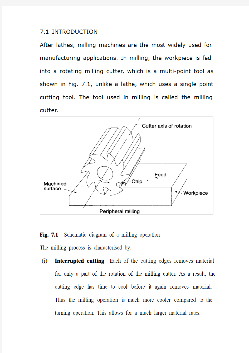
After lathes, milling machines are the most widely used for manufacturing applications. In milling, the workpiece is fed into a rotating milling cutter, which is a multi-point tool as shown in Fig. 7.1, unlike a lathe, which uses a single point cutting tool. The tool used in milling is called the milling cutter.
Fig. 7.1Schematic diagram of a milling operation
The milling process is characterised by:
(i)Interrupted cutting Each of the cutting edges removes material
for only a part of the rotation of the milling cutter. As a result, the cutting edge has time to cool before it again removes material.
Thus the milling operation is much more cooler compared to the turning operation. This allows for a much larger material rates.
(ii)Small size of chips Though the size of the chips is small, in view of the multiple cutting edges in contact a large amount of material is removed and as a result the component is generally completed in
a single pass unlike the turning process which requires a large
number of cuts for finishing.
(iii)Variation in chip thickness This contributes to the non-steady state cyclic conditions of varying cutting forces during the contact of the cutting edge with the chip thickness varying from zero to maximum size or vice versa. This cyclic variation of the force can excite any of the natural frequencies of the machine tool system and is harmful to the tool life and surface finish generated
A milling machine is one of the most versatile machine tools. It is adaptable for quantity production as well as in job shops and tool rooms. The versatility of milling is because of the large variety of accessories and tools available with milling machines. The typical tolerance expected from the process is about ±0.050 mm.
7.2 TYPES OF MILLING MACHINES
To satisfy various requirements milling machines come in a number of sizes and varieties. In view of the large material removal rates
milling machines come with a very rigid spindle and large power. The varieties of milling machines available are:
(i) Knee and Column type
(a) horizontal
(b) vertical
(c) universal
(d) turret type
These are the general purpose milling machines, which have a high degree of flexibility and are employed for all types of works including batch manufacturing. A large variety of attachments to improve the flexibility are available for this class of milling machines.
(ii) Production (Bed) type
(a) simplex
(b) duplex
(c) triplex
These machines are generally meant for regular production involving large batch sizes. The flexibility is relatively less in these machines which is suitable for productivity enhancement.
(iii) Plano millers
These machines are used only for very large workpieces involving table travels in meters.
(iv) Special type
(a) Rotary table
(b) Drum type
(c) Copy milling (Die sinking machines)
(d) Key way milling machines
(e) Spline shaft milling machines
These machines provide special facilities to suit specific applications that are not catered to by the other classes of milling machines.
7.2.1 Knee and Column Milling Machines
The knee(升降台) and column type is the most commonly used machine in view of its flexibility and easier setup. A typical machine construction is shown in Fig. 7.2 for the horizontal axis. The knee houses the feed mechanism and mounts the saddle and table. The table basically has the T-slots running along the X-axis for the purpose of work holding. The table moves along the X-axis on the saddle while the saddle moves along the Y-axis on the guide ways provided on the knee.
The feed is provided either manually with a hand wheel or connected for automatic by the lead screw, which in turn is coupled to the main spindle drive. The knee can move up and down (Z-axis) on a dovetail provided on the column.
Fig. 7.2 Horizontal knee and column type milling machine
The massive column at the back of the machine houses all the power train including the motor and the spindle gearbox. The power for feeding the table lead screw is taken from the main motor through a separate feed gearbox. Sometimes a separate feed motor is provided for the feed gearbox as well.
While the longitudinal and traverse motions are provided with automatic motion, the raising of the knee is generally made manually.
The spindle is located at the top end of the column. The arbour used to mount the milling cutters is mounted in the spindle and is provided with a support on the other end to take care of the heavy cutting forces by means of an overarm with bearing. As shown in Fig.
7.2 the overarm extends from the column with a rigid design. The spindle nose has the standard Morse taper of the suitable size
depending upon the machine size.
The milling cutters are mounted on the arbour at any desired position, the rest of the length being filled by standard hardened collars of varying widths to fix the position of the cutter. The arbour is clamped in the spindle with the help of a draw bar and then fixed with nuts.
Milling machines are generally specified on the following basis:
(i) Size of the table, which specifies the actual working area on the table and relates to the maximum size of the workpiece that can be accommodated.
(ii) Amount of table travel, which gives the maximum axis movement that is possible.
(iii) Horse power of the spindle, which actually specifies the power of the spindle motor used. Smaller machines may come with 1 to 3 hp while the production machines may go from 10 to 50 hp.
Another type of knee and column milling machine is the vertical axis type. Its construction is very similar to the horizontal axis type, except for the spindle type and location.
The vertical axis milling machine is relatively more flexible (Fig. 7.4) and suitable for machining complex cavities such as die cavities in tool rooms. The vertical head is provided with a swiveling facility in horizontal direction whereby the cutter axis can be swivelled. This is
useful for tool rooms where more complex milling operations are carried out.
The spindle is located in the vertical direction and is suitable for using the shank mounted milling cutters such as end mills, In view of the location of the tool, the setting up of the workpiece and observing the machining operation is more convenient.
Fig, 7.3 Vertical knee and column type milling machine
Fig.7.4 Some of the milling operations normally carried out on vertical axis machines
The universal machine has the table which can be swivelled in a horizontal plane at about 45o to either the left or right. This makes the universal machine suitable for milling spur and helical gears as well as worm gears and cams.
7.2.2 Bed Type Milling Machine
In production milling machines it is desirable to increase the metal removal rates. If it is done on conventional machines by increasing
the depth of cut, there is possibility of chatter. Hence another variety
of milling machines named as bed type machines are used which are made more rugged and are capable of removing more material. The ruggedness is obtained as a consequence of the reduction in versatility.
The table in the case of bed type machines is directly mounted on the bed and is provided with only longitudinal motion.
The spindle moves along with the column to provide the cutting action. Simplex machines (Fig. 7.5) are the ones with only one spindle head while duplex machines have two spindles (Fig. 7.6). The two spindles are located on either side of a heavy workpiece and remove material from both sides simultaneously.
Fig. 7.5 Simplex bed type milling machine
Fig. 7.6 Duplex bed type milling machine
7.3 MILLING CUTTERS
There are a large variety of milling cutters available to suit specific requirements. The versatility of the milling machine is contributed to
a great extent by the variety of milling cutters that are available.
7.3.1 Types of Milling Cutters
Milling cutters are classified into various types based on a variety of methods.
(i) Based on construction:
(a) Solid
(b) Inserted tooth type
Based on mounting:
(a) Arbor mounted
(b) Shank mounted
(c) Nose mounted
Base on rotation:
(a) Right hand rotation (counter clockwise)
(b) Left hand rotation (clockwise)
Based on helix:
(a) Right hand helix
(b) Left hand helix
Milling cutters are generally made of high speed steel or cemented carbides. The cemented carbide cutters can be of a brazed tip variety or with indexable tips. The indexable variety is more common since it is normally less expensive to replace the worn out cutting edges than to regrind them.
Plain milling cutters These are also called slab milling cutters and are basically cylindrical with the cutting teeth on the periphery as shown in Fig. 7.7. These are generally used for machining flat surfaces.
Fig. 7.7 Arbor mounted milling cutters for general purpose
Light duty slab milling cutters generally have a face width, which is small of the order of 25 mm. They generally have straight teeth and large number of teeth.
Heavy duty slab milling cutters come with a smaller number of teeth to allow for more chip space. This allows taking deeper cuts and consequently high material removal rates.
Helical milling cutters have a very small number of teeth but a large helix angle. This type of cutter cuts with a shearing action, which can produce a very fine finish. The large helix angle allows the cutter to absorb most of the end load and therefore the cutter enters and leaves the workpiece very smoothly.
Side and face milling cutters These have the cutting edges not only on
the face like the slab milling cutters, but also on both the sides. As a
result, these cutters become more versatile since they can be used for side milling as well as for slot milling.
Staggered tooth side milling cutters are a variation where the teeth are arranged in an alternate helix pattern. This type is generally used for milling deep slots, since the staggering of teeth provides for greater chip space.
Another variation of the side and face cutter is the half side milling cutter, which has cutting edges only on one side. This arrangement provides a positive rake angle and is useful for machining on only one side. These have a much smoother cutting action and a long tool life. The power consumed is also less for these cutters.
Fig. 7.8Special forms of arbor mounted milling cutters
Slitting saws The other common form of milling cutters in the arbor mounted category is the slitting saw. This is very similar to a saw blade in
appearance as well as function. Most of these have teeth around the circumference while some have side teeth as well. The thickness of these cutters is generally very small and is used for cutting off operations or for deep slots.
Special form cutters In addition to the general type of milling cutters described above, there are a large number of special form milling cutters available which are used for machining specific profiles.
Angular milling cutters are made in single or double angle cutters for milling any angle such as 30, 45 or 60o Form relieved cutters are made of various shapes such as circular, corner rounding, convex or concave shapes.
T-slot milling cutters are used for milling T-slots such as those in the milling machine table. The central slot is to be milled first using an end mill before using the T-slot milling cutter. Woodruff key seat milling cutters are used for milling as the name suggests, woodruff key seats Some other special form cutters are dovetail milling cutters and gear milling cutters.
End mills These are shank mounted as shown in Fig. 7.9 and are generally used in vertical axis milling machines. They are used for milling slots, key ways and pockets where other type of milling cutters cannot be used. A depth of cut of almost half the diameter can be taken with the end mills.
The end mills have the cutting edge running through the length of the cutting portion as well as on the face radially up to a certain length. The helix angle of the cutting edge promotes smooth and efficient cutting even at high cutting speeds and feed rates. High cutting speeds(转速?) are generally recommended for this type of milling cutters.
Fig. 7.9 Shank mounted milling cutters and various types of end mills There are a large variety of end mills. One of the distinctions is based on the method of holding, i.e., the end mill shank can be straight or tapered. The straight shank is used on end mills of small size and held in the milling machine spindle with the help of a suitable collet. The tapered shank can be directly mounted in the spindle with the help of the self
holding taper. If the taper is small compared to the spindle taper, then an adopter accommodating both the tapers is used.
The end teeth of the end mills may be terminated at a distance from the cutter center or may proceed till the center (Fig. 7.9 f). Those with the cutting edge up to the center are called slot drills or end cutting end mills since they have the ability to cut into the solid material (Fig. 7.9 g). The other type of end mills which have a larger number of teeth cannot cut into solid material and hence require a pilot hole drilled before a pocket is machined.
The cutting edge along the side of an end mill is generally straight and sometimes can be tapered by grinding on a tool and cutter grinder such that the draft required for mould and die cavities can be automatically generated.
第七章铣削
7.1介绍
除了车床,铣床是制造应用中最广泛使用的。在铣削中,工件向旋转的铣削刀具轴线进给,如图7.1所示,是一个多切削刃刀具,这点和车床不同,车床使用的是单尖切削刀具。在铣削中使用的刀具称为铣削刀具。
圆周铣削
图7.1铣削原理图
铣削过程可以作如下分类:
(1)断续切削
旋转的铣刀中只有一小部分切削刃用来去除材料,因此,切削刃在再开始投入切削之前有时间来冷却,此外,削削操作同旋转运动相比温度更低,这就允许相对较大的材料率。
(2)体积小的切屑
尽管切屑的体积很小,,考虑到多层切削层与大量材料之间的联系已经
消除,导致一些组件主要是通过单次车削而不像需要通过大量切削来完成的车削过程.
(3切削厚度变化
这是由于在切削过程中切削力不稳定的循环变化而导致切屑厚度的变化范围从零到无限大或者反之亦然,这个切削力循环变化可以引起任何机床刀具系统的固有频率同时对刀具寿命和产生的表面光洁度有害。
铣床是大多数的通用机床之一。它适用于批量生产的同时也适用于加工车间和刀具车间。铣床的通用性在于铣床上有大量的附件和可用刀具。在加工过程中,产品产生的预期公差大约为±0.05mm。
7.2铣床的种类
为了满足不同的需求,铣床出现了许多型号和种类。考虑到高材料去除率的铣床,出现了刚性主轴和大功率。常用的几种铣床种类如下:(i)升降台种类
(a)水平的
(b)竖直的
(c)通用的
(d)转塔类型的
这些都是通用铣床,它们有高度灵活性而且应用于所有类型的工件同时包括批量生产。
(ii)生产类型
(a)单一的
(b)复式的
(c)三重的
这些机器大多是为了正常生产,包括大批量生产。它们的灵活性比那些用于提高生产率的机器会相对来说小一点。
(iii)l龙门铣床
这个机器只能用于大量工件包括工作台行程,单位为米。
(iv)专用种类
(a)回转台
(b)鼓形
(c)仿型铣床(开模机)
(d))键槽铣床
(e)花键轴铣床
这类机床提供特别的设备以满足特定的别的种类铣床不能满足的应用。
7.2.1升降台铣床
升降台类机床鉴于它的灵活性和易安装性使得它是最被广泛的应用的机床。典型的卧式水平轴的机床结构如图7.2 所示。升降台支撑着进给机构同时安装着床鞍和工作台。工作台主要地有沿着X轴的T 型槽,这个槽主要是用来工件的夹紧。工作台沿着X轴在床鞍上移动,床鞍沿着Y轴在导轨上移动。进给由手轮手动地提供,或是由导螺杆相连的自动进给,导螺杆转而由主轴驱动。升降台能够在床身提供的衔接上沿Z轴上下移动。
图7.2 卧式升降台铣床
在机床背后巨大的床身内装有所有动力传动机构,包括电动机和主轴变速箱。供给工作台的导螺杆的功率主要通过一个分进给变速箱向主要的电动机获取。有时也有一个单独的进给电动机为进给变速箱提供动力。尽管纵向和横向的运动都由自动运动控制,但升降台的上升一般由手动完成。
主轴位于床身的顶部。常用来安装刀具的心轴安装在主轴上,同时在另一端用带轴承的悬臂提供一种支撑以满足强大的切削力矩。如图7.2所示悬臂用一种刚性设计从床身向外伸出。主轴头端带有根据机床大小选择的合适尺寸的标准莫氏锥度。
铣刀可以再任何需要的位置上安装在心轴上,长度的其余部分用不同宽度的标准紧固轴环填充以固定刀的位置。心轴通过牵引杆在主轴中夹紧,然后用螺母固定。
铣床一般按以下分类:
(i)工作台的大小,它指定了在工作台上的实际工作面积和相关的能
够适应的工件的最大尺寸。
毕业设计外文翻译资料
外文出处: 《Exploiting Software How to Break Code》By Greg Hoglund, Gary McGraw Publisher : Addison Wesley Pub Date : February 17, 2004 ISBN : 0-201-78695-8 译文标题: JDBC接口技术 译文: JDBC是一种可用于执行SQL语句的JavaAPI(ApplicationProgrammingInterface应用程序设计接口)。它由一些Java语言编写的类和界面组成。JDBC为数据库应用开发人员、数据库前台工具开发人员提供了一种标准的应用程序设计接口,使开发人员可以用纯Java语言编写完整的数据库应用程序。 一、ODBC到JDBC的发展历程 说到JDBC,很容易让人联想到另一个十分熟悉的字眼“ODBC”。它们之间有没有联系呢?如果有,那么它们之间又是怎样的关系呢? ODBC是OpenDatabaseConnectivity的英文简写。它是一种用来在相关或不相关的数据库管理系统(DBMS)中存取数据的,用C语言实现的,标准应用程序数据接口。通过ODBCAPI,应用程序可以存取保存在多种不同数据库管理系统(DBMS)中的数据,而不论每个DBMS使用了何种数据存储格式和编程接口。 1.ODBC的结构模型 ODBC的结构包括四个主要部分:应用程序接口、驱动器管理器、数据库驱动器和数据源。应用程序接口:屏蔽不同的ODBC数据库驱动器之间函数调用的差别,为用户提供统一的SQL编程接口。 驱动器管理器:为应用程序装载数据库驱动器。 数据库驱动器:实现ODBC的函数调用,提供对特定数据源的SQL请求。如果需要,数据库驱动器将修改应用程序的请求,使得请求符合相关的DBMS所支持的文法。 数据源:由用户想要存取的数据以及与它相关的操作系统、DBMS和用于访问DBMS的网络平台组成。 虽然ODBC驱动器管理器的主要目的是加载数据库驱动器,以便ODBC函数调用,但是数据库驱动器本身也执行ODBC函数调用,并与数据库相互配合。因此当应用系统发出调用与数据源进行连接时,数据库驱动器能管理通信协议。当建立起与数据源的连接时,数据库驱动器便能处理应用系统向DBMS发出的请求,对分析或发自数据源的设计进行必要的翻译,并将结果返回给应用系统。 2.JDBC的诞生 自从Java语言于1995年5月正式公布以来,Java风靡全球。出现大量的用java语言编写的程序,其中也包括数据库应用程序。由于没有一个Java语言的API,编程人员不得不在Java程序中加入C语言的ODBC函数调用。这就使很多Java的优秀特性无法充分发挥,比如平台无关性、面向对象特性等。随着越来越多的编程人员对Java语言的日益喜爱,越来越多的公司在Java程序开发上投入的精力日益增加,对java语言接口的访问数据库的API 的要求越来越强烈。也由于ODBC的有其不足之处,比如它并不容易使用,没有面向对象的特性等等,SUN公司决定开发一Java语言为接口的数据库应用程序开发接口。在JDK1.x 版本中,JDBC只是一个可选部件,到了JDK1.1公布时,SQL类包(也就是JDBCAPI)
冲压模具技术外文翻译(含外文文献)
前言 在目前激烈的市场竞争中,产品投入市场的迟早往往是成败的关键。模具是高质量、高效率的产品生产工具,模具开发周期占整个产品开发周期的主要部分。因此客户对模具开发周期要求越来越短,不少客户把模具的交货期放在第一位置,然后才是质量和价格。因此,如何在保证质量、控制成本的前提下加工模具是值得认真考虑的问题。模具加工工艺是一项先进的制造工艺,已成为重要发展方向,在航空航天、汽车、机械等各行业得到越来越广泛的应用。模具加工技术,可以提高制造业的综合效益和竞争力。研究和建立模具工艺数据库,为生产企业提供迫切需要的高速切削加工数据,对推广高速切削加工技术具有非常重要的意义。本文的主要目标就是构建一个冲压模具工艺过程,将模具制造企业在实际生产中结合刀具、工件、机床与企业自身的实际情况积累得高速切削加工实例、工艺参数和经验等数据有选择地存储到高速切削数据库中,不但可以节省大量的人力、物力、财力,而且可以指导高速加工生产实践,达到提高加工效率,降低刀具费用,获得更高的经济效益。 1.冲压的概念、特点及应用 冲压是利用安装在冲压设备(主要是压力机)上的模具对材料施加压力,使其产生分离或塑性变形,从而获得所需零件(俗称冲压或冲压件)的一种压力加工方法。冲压通常是在常温下对材料进行冷变形加工,且主要采用板料来加工成所需零件,所以也叫冷冲压或板料冲压。冲压是材料压力加工或塑性加工的主要方法之一,隶属于材料成型工程术。 冲压所使用的模具称为冲压模具,简称冲模。冲模是将材料(金属或非金属)批量加工成所需冲件的专用工具。冲模在冲压中至关重要,没有符合要求的冲模,批量冲压生产就难以进行;没有先进的冲模,先进的冲压工艺就无法实现。冲压工艺与模具、冲压设备和冲压材料构成冲压加工的三要素,只有它们相互结合才能得出冲压件。 与机械加工及塑性加工的其它方法相比,冲压加工无论在技术方面还是经济方面都具有许多独特的优点,主要表现如下; (1) 冲压加工的生产效率高,且操作方便,易于实现机械化与自动化。这是
机械专业毕业论文外文翻译
附录一英文科技文献翻译 英文原文: Experimental investigation of laser surface textured parallel thrust bearings Performance enhancements by laser surface texturing (LST) of parallel-thrust bearings is experimentally investigated. Test results are compared with a theoretical model and good correlation is found over the relevant operating conditions. A compari- son of the performance of unidirectional and bi-directional partial-LST bearings with that of a baseline, untextured bearing is presented showing the bene?ts of LST in terms of increased clearance and reduced friction. KEY WORDS: ?uid ?lm bearings, slider bearings, surface texturing 1. Introduction The classical theory of hydrodynamic lubrication yields linear (Couette) velocity distribution with zero pressure gradients between smooth parallel surfaces under steady-state sliding. This results in an unstable hydrodynamic ?lm that would collapse under any external force acting normal to the surfaces. However, experience shows that stable lubricating ?lms can develop between parallel sliding surfaces, generally because of some mechanism that relaxes one or more of the assumptions of the classical theory. A stable ?uid ?lm with su?cient load-carrying capacity in parallel sliding surfaces can be obtained, for example, with macro or micro surface structure of di?erent types. These include waviness [1] and protruding microasperities [2–4]. A good literature review on the subject can be found in Ref. [5]. More recently, laser surface texturing (LST) [6–8], as well as inlet roughening by longitudinal or transverse grooves [9] were suggested to provide load capacity in parallel sliding. The inlet roughness concept of Tonder [9] is based on ??e?ective clearance‘‘ reduction in the sliding direction and in this respect it is identical to the par- tial-LST concept described in ref. [10] for generating hydrostatic e?ect in high-pressure mechanical seals. Very recently Wang et al. [11] demonstrated experimentally a doubling of the load-carrying capacity for the surface- texture design by reactive ion etching of SiC
电气专业毕业设计外文翻译
附录1:外文资料翻译 A1.1外文资料题目 26.22 接地故障电路开关 我们目前为止报道的接地方法通常是充分的, 但更加进一步的安全措施在某些情况下是必要的。假设例如, 有人将他的手指伸进灯口(如Fig.26.45示)。虽然金属封入物安全地接地, 但那人仍将受到痛苦的震动。或假设1个120V 的电炉掉入游泳池。发热设备和联络装置将导致电流流入在水池中的危害,即使电路的外壳被安全地接地,现在已经发展为当这样的事件发生时,设备的电源将被切断。如果接地电流超过5mA ,接地开关将在5 ms 内跳掉,这些装置怎么运行的? 如Fig.26.46所示,一台小变流器缠绕上导线 ,第二步是要连接到可能触发开合120 V 线的一台敏感电子探测器。 在正常情况下流过导体的电流W I 与中性点上的电流N I 准切的相等,因此流经核心的净潮流(N W I I -)是零。 结果,在核心没有产生电流,导致的电压F E 为零,并且开关CB 没有动作。 假设如果某人接触了一个终端(图Fig.26.45示),故障电流F I 将直接地从载电线漏到地面,这是可能发生的。如果绝缘材料在马达和它的地面封入物之间断开,故障电流也会被产生。在以下任何情况下,流经CT 的孔的净潮流等于F I 或L I ,不再是零。电流被产生,并且产生了可以控制CB 开关的电压F E 。 由于5 mA 不平衡状态只必须被检测出,变压器的核心一定是非常有渗透性的在低通量密度。 Supermalloy 是最为常用的,因为它有相对渗透性典型地70000在通量密度仅4mT 。 26.23 t I 2是导体迅速发热的因素 它有时发生于导体短期内电流远大于正常值的情况下,R I 2损失非常大并且导体的温度可以在数秒内上升几百度。例如,当发生严重短路时,在保险丝或开关作用之前,会有很大的电流流过导体和电缆。 此外,热量没有时间被消散到周围,因此导体的温度非常迅速地增加。 在这些情况下什么是温度上升? 假设导体有大量m ,电阻R 和热量热容量c 。 而且,假设电流是I ,并且那它流动在t 少于15秒期间。 在导体上引起的热 Rt I Q 2= 从Eq.3.17,在功率一定的情况下我们可以计算导体上升的温度差:
软件开发概念和设计方法大学毕业论文外文文献翻译及原文
毕业设计(论文)外文文献翻译 文献、资料中文题目:软件开发概念和设计方法文献、资料英文题目: 文献、资料来源: 文献、资料发表(出版)日期: 院(部): 专业: 班级: 姓名: 学号: 指导教师: 翻译日期: 2017.02.14
外文资料原文 Software Development Concepts and Design Methodologies During the 1960s, ma inframes and higher level programming languages were applied to man y problems including human resource s yste ms,reservation s yste ms, and manufacturing s yste ms. Computers and software were seen as the cure all for man y bu siness issues were some times applied blindly. S yste ms sometimes failed to solve the problem for which the y were designed for man y reasons including: ?Inability to sufficiently understand complex problems ?Not sufficiently taking into account end-u ser needs, the organizational environ ment, and performance tradeoffs ?Inability to accurately estimate development time and operational costs ?Lack of framework for consistent and regular customer communications At this time, the concept of structured programming, top-down design, stepwise refinement,and modularity e merged. Structured programming is still the most dominant approach to software engineering and is still evo lving. These failures led to the concept of "software engineering" based upon the idea that an engineering-like discipl ine could be applied to software design and develop ment. Software design is a process where the software designer applies techniques and principles to produce a conceptual model that de scribes and defines a solution to a problem. In the beginning, this des ign process has not been well structured and the model does not alwa ys accurately represent the problem of software development. However,design methodologies have been evolving to accommo date changes in technolog y coupled with our increased understanding of development processes. Whereas early desig n methods addressed specific aspects of the
机械设计外文翻译(中英文)
机械设计理论 机械设计是一门通过设计新产品或者改进老产品来满足人类需求的应用技术科学。它涉及工程技术的各个领域,主要研究产品的尺寸、形状和详细结构的基本构思,还要研究产品在制造、销售和使用等方面的问题。 进行各种机械设计工作的人员通常被称为设计人员或者机械设计工程师。机械设计是一项创造性的工作。设计工程师不仅在工作上要有创造性,还必须在机械制图、运动学、工程材料、材料力学和机械制造工艺学等方面具有深厚的基础知识。如前所诉,机械设计的目的是生产能够满足人类需求的产品。发明、发现和科技知识本身并不一定能给人类带来好处,只有当它们被应用在产品上才能产生效益。因而,应该认识到在一个特定的产品进行设计之前,必须先确定人们是否需要这种产品。 应当把机械设计看成是机械设计人员运用创造性的才能进行产品设计、系统分析和制定产品的制造工艺学的一个良机。掌握工程基础知识要比熟记一些数据和公式更为重要。仅仅使用数据和公式是不足以在一个好的设计中做出所需的全部决定的。另一方面,应该认真精确的进行所有运算。例如,即使将一个小数点的位置放错,也会使正确的设计变成错误的。 一个好的设计人员应该勇于提出新的想法,而且愿意承担一定的风险,当新的方法不适用时,就使用原来的方法。因此,设计人员必须要有耐心,因为所花费的时间和努力并不能保证带来成功。一个全新的设计,要求屏弃许多陈旧的,为人们所熟知的方法。由于许多人墨守成规,这样做并不是一件容易的事。一位机械设计师应该不断地探索改进现有的产品的方法,在此过程中应该认真选择原有的、经过验证的设计原理,将其与未经过验证的新观念结合起来。 新设计本身会有许多缺陷和未能预料的问题发生,只有当这些缺陷和问题被解决之后,才能体现出新产品的优越性。因此,一个性能优越的产品诞生的同时,也伴随着较高的风险。应该强调的是,如果设计本身不要求采用全新的方法,就没有必要仅仅为了变革的目的而采用新方法。 在设计的初始阶段,应该允许设计人员充分发挥创造性,不受各种约束。即使产生了许多不切实际的想法,也会在设计的早期,即绘制图纸之前被改正掉。只有这样,才不致于堵塞创新的思路。通常,要提出几套设计方案,然后加以比较。很有可能在最后选定的方案中,采用了某些未被接受的方案中的一些想法。
机械类毕业设计外文翻译
本科毕业论文(设计) 外文翻译 学院:机电工程学院 专业:机械工程及自动化 姓名:高峰 指导教师:李延胜 2011年05 月10日 教育部办公厅 Failure Analysis,Dimensional Determination And
Analysis,Applications Of Cams INTRODUCTION It is absolutely essential that a design engineer know how and why parts fail so that reliable machines that require minimum maintenance can be designed.Sometimes a failure can be serious,such as when a tire blows out on an automobile traveling at high speed.On the other hand,a failure may be no more than a nuisance.An example is the loosening of the radiator hose in an automobile cooling system.The consequence of this latter failure is usually the loss of some radiator coolant,a condition that is readily detected and corrected.The type of load a part absorbs is just as significant as the magnitude.Generally speaking,dynamic loads with direction reversals cause greater difficulty than static loads,and therefore,fatigue strength must be considered.Another concern is whether the material is ductile or brittle.For example,brittle materials are considered to be unacceptable where fatigue is involved. Many people mistakingly interpret the word failure to mean the actual breakage of a part.However,a design engineer must consider a broader understanding of what appreciable deformation occurs.A ductile material,however will deform a large amount prior to rupture.Excessive deformation,without fracture,may cause a machine to fail because the deformed part interferes with a moving second part.Therefore,a part fails(even if it has not physically broken)whenever it no longer fulfills its required function.Sometimes failure may be due to abnormal friction or vibration between two mating parts.Failure also may be due to a phenomenon called creep,which is the plastic flow of a material under load at elevated temperatures.In addition,the actual shape of a part may be responsible for failure.For example,stress concentrations due to sudden changes in contour must be taken into account.Evaluation of stress considerations is especially important when there are dynamic loads with direction reversals and the material is not very ductile. In general,the design engineer must consider all possible modes of failure,which include the following. ——Stress ——Deformation ——Wear ——Corrosion ——Vibration ——Environmental damage ——Loosening of fastening devices
毕业设计外文翻译附原文
外文翻译 专业机械设计制造及其自动化学生姓名刘链柱 班级机制111 学号1110101102 指导教师葛友华
外文资料名称: Design and performance evaluation of vacuum cleaners using cyclone technology 外文资料出处:Korean J. Chem. Eng., 23(6), (用外文写) 925-930 (2006) 附件: 1.外文资料翻译译文 2.外文原文
应用旋风技术真空吸尘器的设计和性能介绍 吉尔泰金,洪城铱昌,宰瑾李, 刘链柱译 摘要:旋风型分离器技术用于真空吸尘器 - 轴向进流旋风和切向进气道流旋风有效地收集粉尘和降低压力降已被实验研究。优化设计等因素作为集尘效率,压降,并切成尺寸被粒度对应于分级收集的50%的效率进行了研究。颗粒切成大小降低入口面积,体直径,减小涡取景器直径的旋风。切向入口的双流量气旋具有良好的性能考虑的350毫米汞柱的低压降和为1.5μm的质量中位直径在1米3的流量的截止尺寸。一使用切向入口的双流量旋风吸尘器示出了势是一种有效的方法,用于收集在家庭中产生的粉尘。 摘要及关键词:吸尘器; 粉尘; 旋风分离器 引言 我们这个时代的很大一部分都花在了房子,工作场所,或其他建筑,因此,室内空间应该是既舒适情绪和卫生。但室内空气中含有超过室外空气因气密性的二次污染物,毒物,食品气味。这是通过使用产生在建筑中的新材料和设备。真空吸尘器为代表的家电去除有害物质从地板到地毯所用的商用真空吸尘器房子由纸过滤,预过滤器和排气过滤器通过洁净的空气排放到大气中。虽然真空吸尘器是方便在使用中,吸入压力下降说唱空转成比例地清洗的时间,以及纸过滤器也应定期更换,由于压力下降,气味和细菌通过纸过滤器内的残留粉尘。 图1示出了大气气溶胶的粒度分布通常是双峰形,在粗颗粒(>2.0微米)模式为主要的外部来源,如风吹尘,海盐喷雾,火山,从工厂直接排放和车辆废气排放,以及那些在细颗粒模式包括燃烧或光化学反应。表1显示模式,典型的大气航空的直径和质量浓度溶胶被许多研究者测量。精细模式在0.18?0.36 在5.7到25微米尺寸范围微米尺寸范围。质量浓度为2?205微克,可直接在大气气溶胶和 3.85至36.3μg/m3柴油气溶胶。
STC89C52处理芯片-毕业论文外文翻译
中文翻译 STC89C52处理芯片 电气工程的研究和解决方案中心(ceers) 艾哈迈德为吉.波特 首要性能: 与MCS-51单片机产物兼容、8K字节在系统可编程视频存储器、1000次擦拭周期,全静态操作:0Hz~33Hz、三级加密程序存储器,32个可编程I/O接口线、三个16位定时器(计数器),八个中断源、低功能耗空闲和掉电模式、掉电后间断可唤醒,看门狗定时器、双数值指针,掉电标示符。 关键词:单片机,UART串行通道,掉电标示符等 前言 可以说,二十世纪跨越了三个“点”的时代,即电气时代,电子时代和现已进入的电脑时代。不过,这种电脑,通常指的是个人计算机,简称PC机。还有就是把智能赋予各种机械的单片机(亦称微控制器)。顾名思义,这种计算机的最小系统只用了一片集成电路,即可进行简单的运算可控制。因为它体积小,通常都是藏在被控机械的内部里面。它在整个装置中,起着有如人类头脑的作用,他出了毛病,整个装置就会瘫痪。现在,单片机的种类和适用领域已经十分广泛,如智能仪表、实施工控、通讯设备、导航系统、家用电器等。各种产品一旦用上了单片机,就你能起到产品升级换代的功效,常在产品名称前冠以形容词——“智能型”,如智能洗衣机等。接下来就是关于国产STC89C52单片机的一些基本参数。 功能特性描述: STC89C52单片机是一种低功耗、高性能CMOS8位微控制器,具有8K在系统可编程视频播放存贮器使用高密度非易失性存储器技术制造,与工业80C51 产物指令和引脚完全兼容。片上反射速度允许程序存储器在系统可编程,也适用于常规的程序编写器。在其单芯片上,拥有灵敏小巧的八位中央处理器和在线系统可编程反射,这些使用上STC89C52微控制器为众多嵌入式的控制应用系统提供高度矫捷的、更加有用的解决方案。STC89C52微控制器具有以下的标准功效:8K字节的反射速度,256字节的随机存取储存器,32位I/O串口线,看门狗定时器,2个数值指针,三个16 为定时器、计数器,一个6向量2级间断结构,片内晶振及钟表电路。另外,STC89C52可降至0HZ静态逻辑操作,支持两种软件可选择节电模式、间断继续工作。空闲模式下,CPU停止工作,允许RAM、定时器/计数器、串口、间断继续工作。掉电保护体式格局下,RAM内容被生成,振动器被冻结,单片机一切的工作停止,直到下一个间断或者硬件复位为止。8位微型控制器8K字节在系统中可编程FlashSTC89C52.。
本科毕业设计方案外文翻译范本
I / 11 本科毕业设计外文翻译 <2018届) 论文题目基于WEB 的J2EE 的信息系统的方法研究 作者姓名[单击此处输入姓名] 指导教师[单击此处输入姓名] 学科(专业 > 所在学院计算机科学与技术学院 提交日期[时间 ]
基于WEB的J2EE的信息系统的方法研究 摘要:本文介绍基于工程的Java开发框架背后的概念,并介绍它如何用于IT 工程开发。因为有许多相同设计和开发工作在不同的方式下重复,而且并不总是符合最佳实践,所以许多开发框架建立了。我们已经定义了共同关注的问题和应用模式,代表有效解决办法的工具。开发框架提供:<1)从用户界面到数据集成的应用程序开发堆栈;<2)一个架构,基本环境及他们的相关技术,这些技术用来使用其他一些框架。架构定义了一个开发方法,其目的是协助客户开发工程。 关键词:J2EE 框架WEB开发 一、引言 软件工具包用来进行复杂的空间动态系统的非线性分析越来越多地使用基于Web的网络平台,以实现他们的用户界面,科学分析,分布仿真结果和科学家之间的信息交流。对于许多应用系统基于Web访问的非线性分析模拟软件成为一个重要组成部分。网络硬件和软件方面的密集技术变革[1]提供了比过去更多的自由选择机会[2]。因此,WEB平台的合理选择和发展对整个地区的非线性分析及其众多的应用程序具有越来越重要的意义。现阶段的WEB发展的特点是出现了大量的开源框架。框架将Web开发提到一个更高的水平,使基本功能的重复使用成为可能和从而提高了开发的生产力。 在某些情况下,开源框架没有提供常见问题的一个解决方案。出于这个原因,开发在开源框架的基础上建立自己的工程发展框架。本文旨在描述是一个基于Java的框架,该框架利用了开源框架并有助于开发基于Web的应用。通过分析现有的开源框架,本文提出了新的架构,基本环境及他们用来提高和利用其他一些框架的相关技术。架构定义了自己开发方法,其目的是协助客户开发和事例工程。 应用程序设计应该关注在工程中的重复利用。即使有独特的功能要求,也
机械类外文翻译
机械类外文翻译 塑料注塑模具浇口优化 摘要:用单注塑模具浇口位置的优化方法,本文论述。该闸门优化设计的目的是最大限度地减少注塑件翘曲变形,翘曲,是因为对大多数注塑成型质量问题的关键,而这是受了很大的部分浇口位置。特征翘曲定义为最大位移的功能表面到表面的特征描述零件翘曲预测长度比。结合的优化与数值模拟技术,以找出最佳浇口位置,其中模拟armealing算法用于搜索最优。最后,通过实例讨论的文件,它可以得出结论,该方法是有效的。 注塑模具、浇口位臵、优化、特征翘曲变形关键词: 简介 塑料注射成型是一种广泛使用的,但非常复杂的生产的塑料产品,尤其是具有高生产的要求,严密性,以及大量的各种复杂形状的有效方法。质量ofinjection 成型零件是塑料材料,零件几何形状,模具结构和工艺条件的函数。注塑模具的一个最重要的部分主要是以下三个组件集:蛀牙,盖茨和亚军,和冷却系统。拉米夫定、Seow(2000)、金和拉米夫定(2002) 通过改变部分的尼斯达到平衡的腔壁厚度。在平衡型腔充填过程提供了一种均匀分布压力和透射电镜,可以极大地减少高温的翘曲变形的部分~但仅仅是腔平衡的一个重要影响因素的一部分。cially Espe,部分有其功能上的要求,其厚度通常不应该变化。 pointview注塑模具设计的重点是一门的大小和位臵,以及流道系统的大小和布局。大门的大小和转轮布局通常被认定为常量。相对而言,浇口位臵与水口大小布局也更加灵活,可以根据不同的零件的质量。 李和吉姆(姚开屏,1996a)称利用优化流道和尺寸来平衡多流道系统为multiple 注射系统。转轮平衡被形容为入口压力的差异为一多型腔模具用相同的蛀牙,也存
机械类毕业设计外文文献翻译
沈阳工业大学工程学院 毕业设计(论文)外文翻译 毕业设计(论文)题目:工具盒盖注塑模具设计 外文题目:Friction , Lubrication of Bearing 译文题目:轴承的摩擦与润滑 系(部):机械系 专业班级:机械设计制造及其自动化0801 学生姓名:王宝帅 指导教师:魏晓波 2010年10 月15 日
外文文献原文: Friction , Lubrication of Bearing In many of the problem thus far , the student has been asked to disregard or neglect friction . Actually , friction is present to some degree whenever two parts are in contact and move on each other. The term friction refers to the resistance of two or more parts to movement. Friction is harmful or valuable depending upon where it occurs. friction is necessary for fastening devices such as screws and rivets which depend upon friction to hold the fastener and the parts together. Belt drivers, brakes, and tires are additional applications where friction is necessary. The friction of moving parts in a machine is harmful because it reduces the mechanical advantage of the device. The heat produced by friction is lost energy because no work takes place. Also , greater power is required to overcome the increased friction. Heat is destructive in that it causes expansion. Expansion may cause a bearing or sliding surface to fit tighter. If a great enough pressure builds up because made from low temperature materials may melt. There are three types of friction which must be overcome in moving parts: (1)starting, (2)sliding, and(3)rolling. Starting friction is the friction between two solids that tend to resist movement. When two parts are at a state of rest, the surface irregularities of both parts tend to interlock and form a wedging action. To produce motion in these parts, the wedge-shaped peaks and valleys of the stationary surfaces must be made to slide out and over each other. The rougher the two surfaces, the greater is starting friction resulting from their movement . Since there is usually no fixed pattern between the peaks and valleys of two mating parts, the irregularities do not interlock once the parts are in motion but slide over each other. The friction of the two surfaces is known as sliding friction. As shown in figure ,starting friction is always greater than sliding friction . Rolling friction occurs when roller devces are subjected to tremendous stress which cause the parts to change shape or deform. Under these conditions, the material in front of a roller tends to pile up and forces the object to roll slightly uphill. This changing of shape , known as deformation, causes a movement of molecules. As a result ,heat is produced from the added energy required to keep the parts turning and overcome friction. The friction caused by the wedging action of surface irregularities can be overcome
毕业设计外文翻译
毕业设计(论文) 外文翻译 题目西安市水源工程中的 水电站设计 专业水利水电工程 班级 学生 指导教师 2016年
研究钢弧形闸门的动态稳定性 牛志国 河海大学水利水电工程学院,中国南京,邮编210098 nzg_197901@https://www.360docs.net/doc/5b12917204.html,,niuzhiguo@https://www.360docs.net/doc/5b12917204.html, 李同春 河海大学水利水电工程学院,中国南京,邮编210098 ltchhu@https://www.360docs.net/doc/5b12917204.html, 摘要 由于钢弧形闸门的结构特征和弹力,调查对参数共振的弧形闸门的臂一直是研究领域的热点话题弧形弧形闸门的动力稳定性。在这个论文中,简化空间框架作为分析模型,根据弹性体薄壁结构的扰动方程和梁单元模型和薄壁结构的梁单元模型,动态不稳定区域的弧形闸门可以通过有限元的方法,应用有限元的方法计算动态不稳定性的主要区域的弧形弧形闸门工作。此外,结合物理和数值模型,对识别新方法的参数共振钢弧形闸门提出了调查,本文不仅是重要的改进弧形闸门的参数振动的计算方法,但也为进一步研究弧形弧形闸门结构的动态稳定性打下了坚实的基础。 简介 低举升力,没有门槽,好流型,和操作方便等优点,使钢弧形闸门已经广泛应用于水工建筑物。弧形闸门的结构特点是液压完全作用于弧形闸门,通过门叶和主大梁,所以弧形闸门臂是主要的组件确保弧形闸门安全操作。如果周期性轴向载荷作用于手臂,手臂的不稳定是在一定条件下可能发生。调查指出:在弧形闸门的20次事故中,除了极特殊的破坏情况下,弧形闸门的破坏的原因是弧形闸门臂的不稳定;此外,明显的动态作用下发生破坏。例如:张山闸,位于中国的江苏省,包括36个弧形闸门。当一个弧形闸门打开放水时,门被破坏了,而其他弧形闸门则关闭,受到静态静水压力仍然是一样的,很明显,一个动态的加载是造成的弧形闸门破坏一个主要因素。因此弧形闸门臂的动态不稳定是造成弧形闸门(特别是低水头的弧形闸门)破坏的主要原是毫无疑问。
电气毕业设计外文文献
外文文献: The Intelligent Building One of the benefits of the rapid evolution of information technology has been the development of systems that can measure, evaluate, and respond to change。An enhanced ability to control change has sparked developments in the way we design our physical environment, in particular, the buildings in which we work。As a result, we are witnessing significant growth in the area of "Intelligent Buildings"--buildings that incorporate information technology and communication systems, making them more comfortable, secure, productive, and cost-effective What is an Intelligent Building? An Intelligent Building is one equipped with the telecommunications infrastructure that enables it to continuously respond and adapt to changing conditions, allowing for a more efficient use of resources and increasing the comfort and security of its occupants。An Intelligent Building provides these benefits through automated control systems such as: heating, ventilation, and air-conditioning (HVAC);fire safety;security;and energy/lighting management。For example, in the case of a fire, the fire alarm communicates with the security system to unlock the doors。The security system communicates with the HVAC system to regulate the flow of air to prevent the fire from spreading。 What benefits do Intelligent Buildings offer their owners and occupants? The introduction in the workplace of computers printers photocopiers, and fax machines has increased indoor pollution。Electrical and telecommunications facilities in office buildings are under pressure to satisfy the demands created by the rapid growth of computer and networking technologies。These factors have a definite impact on productivity. New technology can be used to create Intelligent Buildings that address these problems by providing a healthier, more productive, and less energy-intensive work environment。As these are critical factors for business