钢丝螺套 HELICOIL

0100/06.02 The latest generation of thread inserts
Thread technology for high strength fastenings
Simple – fast – long lasting
https://www.360docs.net/doc/5d1183788.html,
Contents
2HELICOIL?plus Thread Technology page
The system3 The technology3 The versions4 The applications5 The advantages 5 – 7 Application examples8 / 9 Materials / Thread forms10 Design guidelines11 Technical data of the thread inserts11a – 17
STRIPFEED?magazined thread inserts18 "pick and place" equipment
Installation19 System components for installation
HELICOIL?plus page Advisory service20 Standard range of HELICOIL?plus manual and machine taps21 HELICOIL?plus machine taps für special requirements22 Thread tolerances of the holding threads23 Manual taps24 – 27 Combined tap and cutting tools26 / 27 Machine taps28 – 31 Internal thread gauges for HELICOIL?plus threads32
Manual installation tools, electrical and battery installation tools and
installation accessories33 – 37 Mechanical installation tools38 – 40 Accessoires for mechanical installation tools41
Semi- and completely automatic installation tools,
tang break-off tool, unscrewing tools42
Examples of equipment and special machines for the semi-automatic
installation of HELICOIL?plus43 HELICOIL?plus repair kits, range kits and HELICOIL?nuts44 B?llhoff and the HELICOIL?plus production45 Subject to technical modifications without notification. All dimensions in mm.
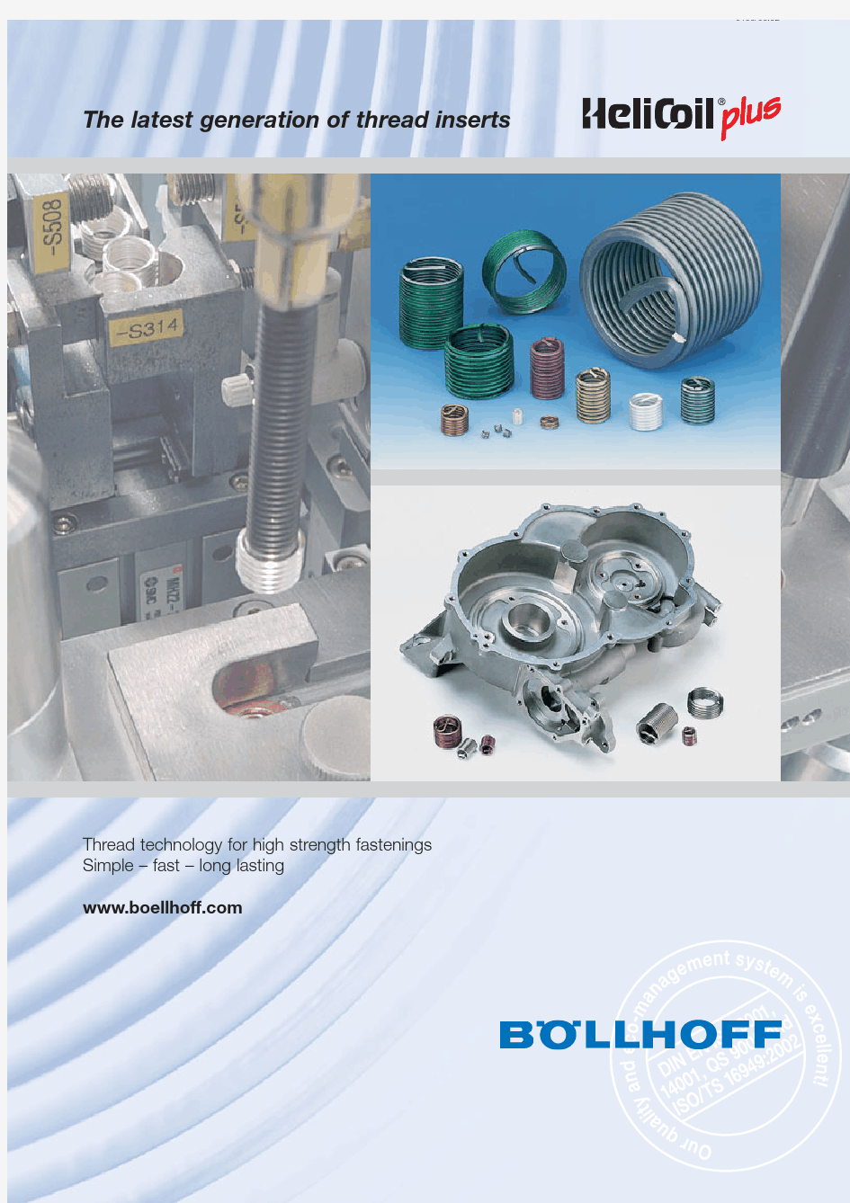
The System
Thread inserts achieve a
heavy-duty connection capability in low-strength metal materials and have been proven practice for over forty years. These thread inserts, made from a well-proven and tested quality stainless steel are formed from rhomboidally profiled wire into a resili-ent spiral. After installation the tang is broken off at the notch (pre-set break-off point).
The latest generation for this technology is called
HELICOIL ?
plus.Due to its optimal fitting structural shape, installation of
HELICOIL ?
plus has been made far more simple. This is guaranteed by the installation area, which facilitates
that the HELICOIL ?
plus can be utilised as a screw and screwed-in. The tool sleeve required until now with its leader cartridge is no longer necessary. Only a fitting mandrel is now required for screwing-in. But the acceptable available structural form tools can still be utilised.
R m =tensile strength minimum 1400 N/mm 2HV =Vickers hardness minimum 425 HV 0,2R Z =roughness depth approximately 2,5 μm
μG
=reduced and constant thread friction, results in a heightened pre-stressing force F V τt
=
reduction in the torsion stress in the screw shank
3
The Technology
HELICOIL ?
plus thread inserts distinguish themselves through a high wearing tensile strength, low thread friction with tight tolerances, a high surface quality as well as corrosive and heat resistance.
The material and nut thread strength pre-determined performance limits are increased through the
Internationally tried and tested HELICOIL ?
plus thread technology.
4The Versions
HELICOIL?plus thread inserts are available in two versions: HELICOIL?plus free running and HELICOIL?plus SCREWLOCK: Both variations distinguish themselves due to an optimal design. As with a screw the threaded inserts are simply screwed in by means of a fitting mandrel. The fitting time is reduced by up to 20% due to the fact that the program of utilisable tools has been so radically extended compared to previous methods of operations.
a HELICOIL?plus free running
The thread insert with its precision-formed rhomboi-
dal profile is coil for coil free running. The result is a
true-to-gauge internal thread, double sided utilisable.
The dimensional accuracy of the ISO thread con-
forms to DIN 13 6H, and 4H for special require-
ments.
The HELICOIL?plus free running is coloured green for
better identification in its fitted condition and the
colour does not come off.
Every B?llhoff original HELICOIL?plus free running
thread insert is unmistakably identified by means of a
diamond shaped quality embossing at the end of the
final coil.
a HELICOIL?plus SCREWLOCK?
HELICOIL?plus SCREWLOCK?offers the same
thread technological advantages as HELICOIL?plus
free running. In addition, a screw-locking section is
worked in, which serves as a screw-locking device.
The locking of the screw is achieved by means of
one or several polygons formed coils, which grip the
threads of the installed screw. In this way an
elastically resilient friction lock is created. The locking
moment achieved in this way is comparable with the
specifications in DIN 267 Part 15, ISO 2320 or can
be individually adapted to problem solutions.
Standard values for the lock moments can be found
in the table on page 7.
The red coloured HELICOIL?plus SCREWLOCK
thread insert, also stamped with the diamond for-
med embossing, should only be utilised with higher
grade screws (starting from 8.8). High grade alloyed
screws should be lubricated according to the recom-
mendations of the manufacturer. The same torque
should be applied as for the HELICOIL?plus
free running.
5
The Applications
HELICOIL ?
plus provides high strength threads, by means of transferring the stress from flank to flank into the hol-ding thread. A system of high reliability, that has been registered for German and International Trade Mark Rights
with world-wide coverage. HELICOIL ?
plus is a guarantee for standardised material and quality requirements for manufactured thread inserts. They are the basis of national standards, aeronautical standards, military standards,and also for in-house standards of leading major users.
a
Design Element
Anywhere where materials of low shearing strength are utilised (for example aluminium, alu-magnesium alloys),
HELICOIL ?
plus is indispensable for thread reinforcement . Branches that are especially effected by this are machine and plant construction, the automobile industry, electronic and medicine technology as well as aero-nautics and the astronautics industries. By use of the thread reinforcement, wear and tear of the nut thread can be ruled out even with regular functions.
HELICOIL ?
plus makes the development of miniaturisation and lightweight design for volume parts possible.
Stability is guaranteed by the use of threading reinforcement with HELICOIL ?
plus.
a
Reject Reclamation and Repairing of Threads
HELICOIL ?
plus thread inserts have been released world-wide for the economical and lasting repairing of dama-ged or worn out threads.
Alongside the repair of valuable individual components, the possibility of recycling damaged threads of rejected large production volume component parts, allowing for the feed back into the production process, is of major importance.
The Advantages
a
Wear and Tear Stability
HELICOIL ?
plus thread inserts are manufactu-red from austenitic chrome-nickel-steel (tensile strength of a minimum 1400 N/mm 2).The formed thread pro-vides a high surface quality. This guarantees a heavy-duty, wear and tear resistant thread with an extremely low constant thread friction force. This allows for a constant pre-stressing being achieved with the identical tightening tor-que upon repeated re-screwing. This leads simultaneously to a better utilisation of the yield point for high strength screws. The torsion stress is noticeably reduced hereby: In comparison with cut threads, the surface
roughness depth is up to 90% lower with HELICOIL ?
plus .
6
The Advantages
a
Stronger Assemblies
The flexible characteristics of the HELICOIL ?
plus thread inserts provide an uniform loading and tension distribution and with that, a perfect thread pitch angle. Pitch and angle defects are balanced out over the entire length of the thread insert.
Therefore an ideal force transfer is achieved between the bolt and the nut thread. The durability of the thread connection is significantly increased. This applies to both static and dynamic work loads.
a
Corrosion Resistance, wide Temperature Range
The material properties of the HELICOIL ?
plus ensure that locking and tight gripping of screws under normal environmental conditions does not occur.
HELICOIL ?
plus thread inserts made from nickel based materials (INCONEL and NIMONIC 90) are available for thermal high stressed thread
connections, with or without any coating. Elasticity and springiness is preserved even under high temperatures.
HELICOIL ?
plus from high-strength hard coated
aluminium has been specially developed for utilisati-on with materials liable to high corrosion such as
magnesium. Contact corrosion is hereby ruled out.
The Advantages
a
Freedom of design
HELICOIL ?
plus thread inserts allow a wide range for the designer in the choice of materials and material thickness. The actual trend towards lightweight design (for example from magnesium) is fulfilled by
HELICOIL ?
plus with highest loading capacity by
means of thread reinforcement with its simultaneous low area requirement. Due to fewer connection points and a reduction in screw sizes, the saving of materials, size and weight with the same or higher
requirements HELICOIL ?
plus leads to a substantial reduction in costs.
a
Fitting Stability
The outer diameter of the HELICOIL ?
plus thread insert is larger than that of the tapped thread by a precisely calculated value in the non-fitted condition. This difference ensures, in addition to the inherent spring action of
the HELICOIL ?
plus thread insert material radial expansion, a stable, play-free positioning in the nut thread.
Additional fixing elements adhesives – such as required for fixed bushes – are no longer necessary. For utilisati-on of hammer driven screws please consult our technical consultant.
Enhanced Screw locking by using of HELICOIL ?
plus SCREWLOCK ?
Thread technology and the polygonal coils of the HELICOIL ?plus SCREWLOCK ensure a high enhanced screw gripping and with that a counteraction of the self-loosening of the screws. An additional fixing connector such as of a splint, wire or washer is not necessary. This reduces costs and ensures easier assembly.
7
Reference values for clamping torque to DIN 267 Part 15 or ISO 2320
Applicable to standard and fine threads Values in Nm for screws class 8.8
Thread
M 3M 4M 5M 6M 8M 10M 12M 14M 16M 18M 201th tightening, max 0,430,901,603,006,0010,515,524,032,042,054,01th loosening, min.0,120,180,290,450,851,52,33,34,56,07,55th loosening, min.
0,08
0,12
0,20
0,30
0,60
1,0
1,6
2,3
3,0
4,2
5,3
Application examples HELICOIL ?
plus Thread Inserts
Automobile, Aeronautics and Astronautics
a Gear box housings made from magnesium alloys a Thread reinforcement for oil drainage screws a Exhaust gas equipment a Satellite technology a Aeroplane power units a
Repeated screwing
a
Maintenance and repairs
Electrical, Plating, Plastics
a Light fittings
a Electrical equipment a
Hammer drill
Machines and Plants
a Printing machines
a High temperature areas
a Expansion threads (adjustment screws)a Repeated screwing
a
Maintanance and repairs
Further Examples
8
Carrier plate for electronic components made from
aluminium pressure die-casting
Machine construction consoles Material: G-AlSi9 Mg
HELICOIL ?
plus
M 8 x 12 free running
Oil drainage feature of a car sump made from aluminium Screw reinforcement with
HELICOIL ?
plus
M 14 x 1,5 x 14 free running
Steering gear housing
made from aluminium
HELICOIL ?
plus M 14 x 1,5 x 14
free running
9
Further Examples HELICOIL ?
plus
Thread Inserts
Car gearbox cover made from
aluminium die-cast
HELICOIL
?
plus
M 6 x 6 free running
Car roof railing brace made from aluminium die-cast with
HELICOIL ?
plus
M 6 x 6 SCREWLOCK
?
Housing made from aluminium alloy Flanges with
HELICOIL ?
plus
M 5 x 10 SCREWLOCK
?
Right angle grinder gearbox housing made from aluminium.
HELICOIL ?
plus
M 10 x 15 SCREWLOCK ?
HELICOIL ?
plus
M 6 x 12 free running
Engine support for garden chopper made from aluminium Screw loss safety device by
means of HELICOIL ?
plus SCREWLOCK ?
M 8 x 12
Housing for electronic components made from
aluminium.
HELICOIL ?
plus SCREWLOCK
?
Drive over protection for a
lighting fitting mounted into the ground.
Material: aluminium die-cast
HELICOIL
?
plus
M 8 x 12 free running
Nuts in use high temperature
areas with HELICOIL ?
fittings
made from INCONEL – silver plated and nuts with
HELICOIL
?
SCREWLOCK ?as a screw loss safety device.
HELICOIL?plus Thread Technology
Materials
?Not possible for M 2 and M 2,5.
HELICOIL?plus thread inserts complying with multiple requirements and standards from general industry, aerospace
industry like DIN 8140, DIN 65536, LN 9039, LN 9499.
Further standards (p.e. MS or EN-standards) upon inquiry.
10
The guideline values must be assessed so that the screw is always the weakest connection member. Falling short of recommended nominal lengths is acceptable, provided it is proven as acceptable by testing.Intermediate lengths are also available.
The rating of the temperature stressed screw connection must take the change of temperature dependant materi-als into consideration.
Guideline values for determining the length of the HELICOIL ?
plus thread insert relative to the parent material and the screw yield point, valid for temperatures of 20°C
Strength of the parent material Screw quality category 11
HELICOIL ?
plus Thread Technology Design Guidelines
Determination of the Nominal Lengths
Minimum Wall Thickness
Assessment of the minimum wall thickness is mainly pre-determined by the individual operating data. These in turn determine the strength of the material and the length of the thread. The quoted guideline value formu-la applies to aluminium, cast and wrought alloys and a
HELICOIL ?
plus screw-in thread length of 1.5 d.d
=nominal diameter
D HC =HELICOIL ?
plus outer diameter a
=
remaining wall thickness
Graphic representation for the example M 10 x 15:
HELICOIL ?
plus thread insert, inserted
HELICOIL ?
plus thread insert, inserted,
with screw
M 10
M 10
M 10
Mitnehmerzapfen entfernt Mitnehmerzapfen nicht entfernt HELICOIL plus 4130 0100 015
?
HELICOIL plus 4130 0100 015
?
HELICOIL plus 4130 0100 015
?
14,2
14,2
m a x . 14,2
Tang removed Tang not removed
HELICOIL ?
plus Thread Inserts
11a
HELICOIL ?
plus Thread Inserts Technical Data
Please fold this page outward for reading
11b
W
d 1
notch
tang
free running
The free running and SCREWLOCK ?thread insert control values are W and d 1, when not inserted.
Its length can only measured when the insert is in position.Holding thread
Composition
d =thread diameter P =pitch
d 1=outer diameter of thread insert prior to installation W =number of coils prior to installation D HC =outer thread of tapped hol
e D 1HC =thread core diameter
B =recommended twist drill diameter
t 1=
minimum depth of core hole according to DIN 76 Part 1
t 2=nominal length of thread insert and minimum length of holding thread t 3=maximum screw-in depth if tang has not been broken off
t 5
=distance of thread insert from separating surface = 0.25 P , if t 2complies with the above mentioned minimum value
?90° countersinking or deburring before tapping:Countersinking diameter = D HC + 0,1.
a
By utilisation of HELICOIL ?
plus thread inserts in series pro-duction it is recommended that the values t 1and t 2at a minimum however the size of 1 x P is always added.
? Materials or surfaces are always to be recorded with the
5th digit of the ordering ref. no.:
123= Stainless steel A 4, X 6 CrNiMoTi 17 12 24= Inconel X 750, NiCr 15 fe 7 TiAl, silver plated*5= Inconel X 750, NiCr 15 fe 7 TiAl, polished
6= Stainless steel A 2, X 5 CrNi 18 10, cadmium plated 7= Stainless steel A 2, X 5 CrNi 18 10, magazine loaded**8= Bronze, CuSn 6, magazine loaded**Other materials upon request
* utilise special tools ** see page 18
All dimensions in mm. Subject to technical modifications.
see folding page 11b Further thread inserts on the following pages 12
see folding page 11b Further thread inserts on the following pages
13
see folding page 11b Further thread inserts on the following pages 14
see folding page 11b Further thread inserts on the following pages
15
see folding page 11b Further thread inserts on the following pages 16
see folding page 11b
17
18
Magazined HELICOIL ?
plus Thread Inserts for Optimized Installation
HELICOIL
?
plus STRIPFEED
?Magazined HELICOIL ?
plus thread inserts offer advantages especially when working with smaller thread inserts.
Hand operated and stationary installation devices are available for this.
The working advantages for short and long series are:a more simple handling
a an improvement to the working conditions in production assembly a performance improvement due to reliable feeding a reduction in costs
Inch sizes: please refer to separate catalogue 0101
Thread Ordering nom. ?ref. no.M 24148 002 0000M 2,54148 002 0000M 34148 002 0000M 3,54148 002 0000M 44148 004 0000M 54148 004 0000M 64148 006 0000M 8
4148 008 0000
Withdrawal equipment "pick and place"Installation of HELICOIL ?
plus
HELICOIL ?
plus Withdrawal Equipment pick and place
19
Installation of HELICOIL ?
plus Thread Inserts
Preparation of Work Piece
a
Drilling of the core hole
Standard commercial twist drills are used.
Reference points for diameters and core hole depths are found on pages 11 to 17.
90° countersinkung or deburring before tapping:countersinking diameter =D HC
+ 0,1 mm
a
Tapping
System adapted original HELICOIL ?
plus taps must be used for tapping the thread. Recommendations for the selection of suitable manual and machine
taps are listed on pages 21 to 31. HELICOIL ?
plus internal thread limit gauges must be used for
checking that the thread is true to gauge. (Refer to page 32).
a Thread forming
Non-tapping production of female threads by the use of thread formers is the rational method of production for many materials today; this also
applies to HELICOIL ?
plus (refer to pages 30/31).
Installation process
a
Fitting the thread insert
Installation is possible either from hand or by the use of a mechanical installation tool or an automatic
installation machine. The HELICOIL ?
plus thread insert is screwed onto the installation mandrel with its tang pointing downwards (3A), fitted into the pre-stressing cartridge (3B) or placed onto the fly-over tool (3C)and the equipment is then placed over the tapped hole.
a Installation
By means of revolving the thread tang (4A), the mandrel (4B) or the fly-over tool (4C) by hand or starting the driver the thread insert is screwed in. It must be installed with a minimum of 0.25 P under-neath the surface (refer to page 11 t 5).a Breaking the tang off
For creation of a through-hole thread the tang is bro-ken off at the notch. This is completed by the use of a tang break-off tool (5A and 5B). For threads of M 14 fine and normal gradients, a pair of pointed pliers’(5C) can break off the tang.
The tang must not be removed for blind hole threads if the maximum screw-in depth t 3of the screw is adhered to.
3A 3B 3C
4A 4B 4C
5A 5B 5C
钢丝螺套安装步骤及钢丝螺套的使用方法
钢丝螺套安装步骤及钢丝螺套的使用方法 钢丝螺套安装使用方法主要包括以下四个环节:一、钻孔二、攻牙三、安装四、去尾柄四个步骤。要求严格的钢丝螺套安装步骤还需在第二步攻牙以后,用专用钢丝螺套底孔塞规对攻好牙的底孔进行检测,通规能通,止规能止的状态下才能进行下一步钢丝螺套安装操作。此外对安装不好的钢丝螺套可采用专用取套工具—卸套器将其取出。 ?1 钻孔 钢丝螺套安装步骤第一步---钻孔 使用表中所列的标准钻头钻孔, 钻孔深度大于或等于钢丝螺套安装深度;注意不要将孔钻成锥形, 切屑不要掉入。钻孔后锪孔不应超过0.4 螺距深度, 因为锪孔过大不利于钢丝螺套的旋入。 使用表中所列的标准钻头钻孔, 钻孔深度大于或等于钢丝螺套安装深度;注意不要将孔钻成锥形, 切屑不要掉入。钻孔后锪孔不应超过0.4 螺距深度, 因为锪孔过大不利于钢丝螺套的旋入。
2 攻丝 ?钢丝螺套安装步骤第二步就是攻丝 使用标有规定螺纹规格的钢丝螺套专用丝锥攻丝, 攻丝的长度必须超过钢 丝螺套长度, 对于通孔, 要全部攻丝; 攻丝的精度决定最终标准内螺孔的公差带, 使用者要适当地选择攻丝方法和润滑, 盲孔攻丝要适当用力, 以防折断丝锥。攻丝后, 螺纹孔应清理, 一般用压缩空气喷枪吹, 盲孔时还应使用带径向孔的长喷枪自下而上清理, 也可以用清洗的方法清理螺纹孔。螺纹孔精度高时, 应用专用钢丝螺套底孔塞规进行检查。 3 安装 ?钢丝螺套装配操作第三步就是借助钢丝螺套专用扳手进行安装 在一般情况下应用手工安装器进行钢丝螺套安装。钢丝螺套放入安装工具内, 使安装柄嵌入导杆槽内转动安装工具手柄使钢丝螺套旋入螺孔, 并使其距表面留有0.25-0.75 圈空螺纹。少量安装钢丝螺套时和M14×2 以上粗牙钢丝螺套安装时可采用“T ”型开槽或螺纹头简易工具安装, 并注意不 要在钢丝螺套安装柄上施加较大的轴向力以防“ 乱扣” 。钢丝螺套安装后, 为检查所形成的标准内螺纹孔精度等级, 可用相应的级别塞规检验。 4 去柄
钢丝螺套的性能与参数汇总
1、钢丝螺套介绍 钢丝螺套是一种新型的内螺纹紧固件,分为普通型和锁紧型两种,是由高 精度菱形截面的不锈钢丝精确加工而成的一种弹簧状内外螺纹同心体,锁 紧型是在普通型的基础上增加一圈或几圈锁紧圈。钢丝螺套嵌入铝、镁合 金、铸铁、玻璃钢、塑料等低强度的工程材料的螺纹孔中,能形成标准的 M,MJ螺纹,具有连接强度高,抗震、抗冲击和耐磨损的功能,并能分散 应力保护基体螺纹,大大延长基体的使用寿命。另外,钢丝螺套还可以在 原基体上的螺纹脱扣或乱牙时,作为修复手段,不需加大螺丝尺寸,能快速有效的修复到原始状态,而不致造成整个基体报废,快速经济。 2、安装钢丝螺套后的补偿作用 任何阴阳螺纹都会存在螺距及螺纹角度的加工偏差,这意味着 在螺纹旋合后只有一、二扣螺纹真正接触上。当承受负荷时, 螺钉会变形而导致更大的偏差,其结果是,大约70%的载荷都 承加在螺纹口端部的二扣螺纹上,这会导致极大的应力集中而 使予紧力过早丧失,从而导致紧固松动而失效。因此,螺距和 牙型角的偏差可造成: a.阴、阳螺纹旋合不良; b.螺纹牙面承载不均匀; c.予紧力过早丧失; d.坚固实效。 钢丝螺套安装之后,有效地改善了螺纹连接的轴向及径向的配合效 果。当承受载荷时,可有效地弥补螺纹孔与螺钉之间存在的螺距及螺 纹角的偏差,使每一牙螺纹都得到良好旋合,从而使负载及其产生的 应力均匀地分布在旋合面的每一牙螺纹上,而不会导致任何的应力集 中。予紧力一旦减小,还能保持稳固的连接,从而确保紧固。因此, 螺套可以有效地补偿螺距及牙型角的偏差。其优良的特性体现为: A.有效地改善螺纹旋合面的配合; B.均匀地分布罗纹承受的载荷; C.保持长久的螺纹予紧力; D.有效地减少应力集中,极大地延长紧固件寿命。 3、钢丝螺套的优点 延长使用寿命:由于钢丝螺套是不锈钢材料,具有较高硬度,使较软的基件螺纹寿命增加几十到几百倍;增加了其强度,也避免了脱扣,乱扣现象的发生。 增加连接强度:可用于铝镁等软低强度合金材料、木材、塑料、橡胶等易变形低强度材料,避免滑丝、错牙等现象。 增大受力面:可用于要求有强连接而又不能增加螺孔直径的薄体机件。 改善连接条件,增加螺纹连接的承载力和抗疲劳强度:使用钢丝螺套可以消除螺钉与螺孔之间的螺距和牙型偏差,使载荷均匀分布,从而提高了螺纹连接的承载能力和抗疲劳强度。可用于陶瓷、电木、玻璃等硬脆易碎材料的连接紧固。有效防止碎裂现象。
最新钢丝螺套底孔尺寸
钢丝螺套底孔孔径的选择 攻螺纹前的螺纹护套底孔直径应能使攻螺纹后的螺纹内径符合安装钢丝螺套用的螺纹内径的规定(HB5515-96 或GJ B119.3-86) 选择螺纹护套底孔钻头直径时应考虑不同材料钻孔及攻丝时可能产生产差异。 在没有标准资料的情况下也可参照下列公试计算选择钻头直径 D钻头=d+(0.25-0.3)p D——螺纹公称直径 P——螺距 钢丝螺套底孔孔深的选择 由于钢丝螺套只能装至完全螺纹部分同时还需低于端面L1(见下图),因此对于盲孔钻孔深度L应为: L=L0+L1+L2 L0——钢丝螺套旋入螺孔后的长度 L1=(0.5-1.5)P L2=5p L=L0+6p 对于通孔钻孔深度L应为:
L=L0+2p 根据钢丝螺套自由状态圈数,可从相应标准中查出装配状态的长度L0。 钢丝螺套底孔钻头直径选择标准 钢丝螺套在安装之前,钻孔环节参考选用使用表中所列的标准钻头钻孔, 钻孔深度大于或等于钢丝螺套安装深度;注意不要将孔钻成锥形, 切屑不要掉入。钻孔后锪孔不应超过0.4 螺距深度, 因为锪孔过大不利于钢丝螺套的旋入。 代数 方程(组) ★重难点★一元二次方程及其解法;方程的有关应用题(特别是行程、工程问题)一、基本概念 1.方程、方程的解(根)、方程组的解、解方程(组) 二、一元二次方程 1.定义及一般形式: 2.解法:⑴直接开平方法(注意特征)⑵配方法(注意步骤—推倒求根公式)
⑶公式法: ⑷因式分解法(特征:左边=0) 3.根的判别式:24b ac ?=- 4.根与系数的关系(韦达定理):1x +2x =b a -, 1x 2x =c a 逆定理:若 ,则以1x ,2x 为根的一元二次方程是:a (x-1x )(x-2x )=0。 5.常用等式: 三、 可化为一元二次方程的方程 1.分式方程 ⑴定义 ⑵基本思想: 去分母 ⑶基本解法:①去分母法②换元法(如, ) ⑷验根及方法 2.无理方程 ⑴定义 ⑵基本思想: 分母有理化 ⑶基本解法:①乘方法(注意技巧!!)②换元法(例, ) ⑷验根及方法 3.简单的二元二次方程组 由一个二元一次方程和一个二元二次方程组成的二元二次方程组都可用代入法解。 四、 列方程解应用题 一概述 列方程(组)解应用题是中学数学联系实际的一个重要方面。其具体步骤是: ⑴审题。理解题意。弄清问题中已知量是什么,未知量是什么,问题给出和涉及的相等关系是什么。 ⑵设元(未知数)。①直接未知数②间接未知数(往往二者兼用)。一般来说,未知数越多,方程越易列,但越难解。 ⑶用含未知数的代数式表示相关的量。 ⑷寻找相等关系(有的由题目给出,有的由该问题所涉及的等量关系给出),列方程。一般地,未知数个数与方程个数是相同的。 ⑸解方程及检验。 ⑹答案。
螺纹牙套钻孔尺寸表
公制钢丝螺套使用参数表符号说明: d--钢丝螺套公称直径(螺钉公称直径)K--钢丝螺套公称长度t--丝套公称长度P--螺距 do--钻丝套安装用钻头直径Dz--钢丝螺套自由状态下外径N--钢丝螺套自由状态下圈数螺纹规格d×p k×d t(mm) do(mm) Dz(mm) N(≈) 2×0.4 1d 1.5d 2d 2 3 4 2 2.6-2.8 2.9 4.7 6.5 2.5×0.45 1d 1.5d 2d 2.5 3.75 5 2.6 3.3-3.5 3.5 5.9 8.1 3×0.5 1d 1.5d 2d 3 4.5 6 3.1 3.8- 4.0 4 6.3 8.7 4×0.7 1d 1.5d 2d 4 6 8 4.1 5.15-5.35 3.7 6 8.4 5×0.8 1d 1.5d 2d 5 7.5 10 5.2 6.35-6.6 4.3 6.9 9.7 6×1 1d 1.5d 2d 6 9 12 6.2 7.6-7.85 4.2 7 9.6 7×1 1d 1.5d 2d 7 10.5 14 7.2 8.65-8.9 5.4 8.5 11.6 8×1 1d 1.5d 2d 8 12 16 8.2 9.85-10.1 6.1 9.5 13 8×1.25 1d 1.5d 2d 8 12 16 8.3 9.85-10.1 4.7 7.4 10.6 10×1 1d 1.5d 2d 10 15 20 10.2 12.1-12.5 7.6 12 16.3 10×1.5 1d 1.5d 2d 10 15 20 10.3 12.1-12.5 5 8 11.2 12×1.5 1d 1.5d 2d 12 18 24 12.4 14.4-14.8 6.2 9.8 13.5 12×1.75 1d 1.5d 2d 12 18 24 12.4 14.4-14.8 5.2 8.4 11.7 14×1.5 1d 1.5d 2d 14 21 28 14.4 17.2-17.7 7 11.2 15.3 16×1.5 1d 1.5d 2d 16 24 32 16.4 19.4-19.9 8.3 13 17.7 16×2 1d 1.5d 2d 16 24 32 16.5 19.4-19.9 6.0 9.7 13.3 18×1.50.5d 1.0d 1.5d 9 18 27 18.4 21.5-22 4.4 9.5 15 20×1.50.75d 1d 1.5d 15 20 30 20.4 23.7-24.2 8 10.7 16.7 1d 20 6.3 自由状态圈数
钢丝螺套使用常见问题
钢丝螺套使用常见问题 1.丝锥攻丝困难,易折断怎么办? (1)底孔钻头选用过小:根据基体材质换用合适直径的钻头。 (2)钻头磨损严重致底孔钻成锥形:换用新钻头。 (3)底孔打歪:底孔报废。 (4)所选丝锥与基体材料不合适:换用适合基体材料的丝锥。 (5)直接使用成型锥所致:先用Ⅰ锥攻丝。 (6)丝锥磨损严重:以钢丝螺套专用内螺纹底孔塞规检测,若通规不通即要换用新丝锥。 (7)攻丝时,丝锥与底孔不同心:正确操作。 2.钢丝螺套装入底孔困难怎么办? (1)使用简易扳手因钢丝螺套得不到预压缩致扭力过大:换用套筒扳手。
(2)用普通型钢丝螺套的安装扳手装锁紧型钢丝螺套或相反:换用与钢丝螺套匹配的安装扳手。 (3)套筒扳手引导螺纹磨损严重致钢丝螺套预压缩不到位:用钢丝螺套专用内螺纹底孔塞规检测扳手引导螺纹,若止规不止即要选用新套筒扳手。 (4)底孔未清理或清理不符合要求:清理到利于钢丝螺套的安装。 (5)去毛刺性质的锪孔过深:锪孔不应超过0.4倍螺距深度。 (6)钻头选用过小:换用合适直径的钻头。 (7)丝锥磨损严重:用钢丝螺套专用内螺纹底孔塞规检测,若通规不通即要选用新丝锥。 (8)钢丝螺套R角过大:与生产厂家调换。 (9)安装柄偏离圆心过大:用钳子修正或与生产厂家调换。 (10)钢丝螺套自由状态下外径过大:若不易通过套筒扳手引导螺纹即与生产厂家调换。 (11)基体结构复杂:视具体情况与生产厂家配合解
决,例如基体表面与内螺纹距离过长且不能容纳扳手套筒,需特制安装扳手。 3.钢丝螺套使用过程中出现跳扣怎么办? (1)用锁紧型钢丝螺套的安装扳手装普通型钢丝螺套:换用与螺套匹配的安装扳手。 (2)在钢丝螺套安装柄上施加轴向力过大:不应施加轴向力。 (3)选用钻头过大致内螺纹牙型浅:底孔报废,换用合适直径的钻头。 (4)丝锥磨损严重致内螺纹牙型浅:用钢丝螺套专用内螺纹底孔塞规检测,通规不通即换用新丝锥。 (5)钢丝螺套牙型半角误差过大:与生产厂家调换。 (6)钢丝螺套菱形丝型面严重超差:与生产厂家调换。 (7)安装完毕冲断安装柄时用力过大:取出重装或换用有安装柄的钢丝螺套。 4.钢丝螺套安装柄在装配过程中非正常折断怎么办?
钢丝螺套安装指导书
青岛威奥轨道集团(四机工模具有限公司) 钢丝螺套安装使用作业指导书 编 制: 审 核: 批 准: 文件编号:VA-SJTE-ZY-083 版本号: A.0 版本号 Version number 变更内容 Changed content 变更日期 Changed date 编制 Editor A.0 初次编制The first editor2012.11.21 11/21/2012曲旭杰 Halley QU
1.适用范围 Scope of application 本规范适用于本公司生产制造的所有产品,本规范规定了钢丝螺套的规格型号和使用,是 本公司产品制造和检查验收的基本技术依据。适用于公司所有的钢丝螺套产品的采购和安装使 用。 2 编制目的 Preparation of purpose 为了防止在使用和采购钢丝螺套产品中产生失误和错用。对于采购和使用起指导作用! 3钢丝螺套介绍: 钢丝螺套(简称丝套)是为保护有色金属螺纹孔而发展的嵌入物,适用于螺纹连接。旋入并紧固在被 连接件之一的螺纹孔中,形成标准内螺纹,螺栓(或螺钉)再拧入其中。以冷轧不锈钢线制造成螺旋 状内外同心体螺纹线圈,横切面呈菱形,形状类似于螺旋弹簧,具有较高的硬度及较好的表面粗糙度。 安装钢丝螺套使用专用的丝锥及安装工具攻丝和安装,螺套装于螺孔或螺母中,有减轻螺纹牙受力不 纹的磨损和抗腐蚀性能。延长螺孔寿命 4钢丝螺套安装工具 狭义的钢丝螺套安装工具是专指钢丝螺套安装扳手,主要用
于钢丝螺套在螺纹底孔内的安装,其基本原理是使钢丝螺套通过一段引导螺纹,迫使外径收缩,以便顺利装入底孔,分为手动及自动安装扳手。广义的钢丝螺套安装工具包括了以下几种 1、专用丝锥:用于加工钢丝螺套安装孔的内螺纹。 2、安装扳手:用于将钢丝螺套装入内螺纹孔中。 3、冲断器:用于折断钢丝螺套安装柄; 4、卸套器:用于取出装入螺纹孔中的钢丝螺套 5、螺纹塞规:用于检验安装钢丝螺套的内螺纹孔。 5钢丝螺套分类 1,功能分类 l普通型螺纹丝套(Helicoil Free-Running Inserts)标记“FR” A、锁紧型螺纹丝套(Helicoil Screw Lock Inserts) 标记“SL” 2、按钢丝螺套材料分类 A、Cr-Ni不锈钢材料:通过强度和材料的组合,在通常情况下使用,在轻微型结 构、铝合金结构、海水、含氯液体、增加抗腐蚀性下使用。 B、铜合金材料:在要求用铜的情况下或经常调节转动的螺纹连接时使用;在要求 用于导电或自润滑等情况时使用。 C、高温合金材料:温度在500——750℃时耐热使用;对宇航装配技术、飞机发动 机、内燃机涡轮压气机在750℃内作业时使用。 3、螺纹体制分类 A、国际标准ISO“M,MJ”系列钢丝螺套 螺纹系列标记“M”,“MJ”;火花塞螺纹(Spark plug Thread)丝套在此系列 B、统一螺纹“UN”系列钢丝螺套(UNIFIED Thread Series) 粗牙螺纹标记“UNC”,细牙螺纹标记“UNF”,超细牙螺纹标记“UNEF” C、非螺纹密封的管螺纹(British Standard Pipe Thread)螺纹标记号为“G”
钢丝螺套特点、分类、应用(有图解)
钢丝螺套 一、特点 特点1:自由状态的钢丝螺套直径比其欲装入的螺纹孔直径稍大,装配时使钢丝螺套经过安装扳手螺纹引导圈受扭力从而使其直径变小,进入螺孔中,装好以后,钢丝螺套产生类似弹簧膨胀的作用,使其牢固地固定在螺纹孔内,不会因螺钉的旋出而被带出,不会随螺钉的运动而运动。
特点2:增加螺纹连接的承载能力和疲劳强度:钢丝螺套使螺钉与安装钢丝螺套的螺孔之间形成弹性连接,因而消除了内外螺纹之间的螺距和牙型半角误差,可在规定的长度上使每圈螺纹上的负荷均匀分布,从而加强了内螺纹,并能减振,因此可以提高零件螺纹连接的疲劳强度。 特点3:钢丝螺套由极硬的冷轧不锈钢丝绕制而成,似镜的表面减少了磨擦和磨损,可使螺钉上由于磨擦而产生的扭力减少90%,从而用最小的旋紧螺钉力矩得到最大予紧力矩和螺钉拉力,防止螺钉松脱,使合金钢螺钉处于最佳使用状态。
特点4:由于钢丝螺套优良的抗腐蚀性能使之能在多种材料和通常环境条件下确保其适用性,使用钢丝螺套的组合件不会滞住。 特点5:钢丝螺套在高温下可以阻止螺纹连接卡死或擦伤。 特点6:省料:与普通标准内螺纹相比,在同样的强度条件下,使用钢丝螺套后,为了尽可能好的利用屈服极限,可选用尺寸较小,强度较高的螺钉,这样就可以大量节约材料,减轻重量和缩小体积。 特点7:锁紧型钢丝螺套能把螺钉锁紧在钢丝螺套安装后形成的螺纹孔中,在受振和冲击时,可使螺钉不致松扣,比通常锁紧装置工艺性能好。 特点8:简化结构设计和装配,可以取代螺栓螺母联接方式使之更为简单。
二、分类 ●按钢丝螺套安装柄的有无分类 A、有安装柄钢丝螺套(普通型表示为:FR;锁紧型表示为:SL) B、无安装柄钢丝螺套(普通型表示为:NFR;锁紧型表示为:NSL)
推荐常用钢丝螺套规格
推荐常用钢丝螺套规格 (适用于专用工具、夹具、测试装置和设备) 序号 钢丝螺套规格 钢丝螺套底孔直径 1 ST4×0.7×6K 普通型 2 ZST4×0.7×6K φ4.15+0.14 自锁型 3 ST5×0.8×6K 普通型 4 ZST5×0.8×6K φ5.17+0.16 自锁型 5 ST6×1×6K 普通型 6 ZST6×1×6K φ6.22+0.19 自锁型 7 ST8×1.25×6K 普通型 8 ZST8×1.25×6K φ8.27 +0.212 自锁型 9 ST10×1.5×6K 普通型 10 ZST10×1.5×6K φ10.32+0.236 自锁型 11 ST12×1.75×6K 普通型 12 ZST12×1.75×6K φ12.38 +0.265 自锁型 13 ST14×2×6K 普通型 14 ZST14×2×6K φ14.43+0.30 自锁型 15 ST16×2×6K 普通型 16 ZST16×2×6K φ16.43+0.30 自锁型 17 ST3×0.5×6K 普通型 18 ZST3×0.5×6K φ3.1 +0.112 自锁型 17 ST2.5×0.45×6K 普通型 18 ZST2.5×0.45×6K φ2.6 +0.10 自锁型
说明: 1 对于普通精度的螺栓(螺钉),自由状态下钢丝螺套的圈数一般选6圈或8圈;理论分析也证明,多于8圈是不必要的;在某些使用场所(比如薄壁的情况), 4圈也是可接受的。 2 在没有振动的使用情况下,优先选择普通型钢丝螺套;有振动的使用场所,选择自锁型钢丝螺套。 3 库存钢丝螺套是有折断槽型的,在图样上要注明后缀K(折断槽型),若不需要或不能折断,可以在图样上说明;这是减少库存量的要求。 4 在铝合金、20钢、尼龙1010(聚酰胺)、SFBN(聚四氟乙烯)等低强度材料上的螺纹孔,推荐使用钢丝螺套。 5 表中所列钢丝螺套全部为粗牙螺纹。 6 表中所列普通型钢丝螺套有常备库存。 7 钢丝螺套的图样画法,”GB4459.1-84 机械制图螺纹及螺纹紧固件画法”有详细规定,参见Paragraph 4.4。
钢丝螺纹套规格
钢丝螺套的标记方法、螺纹扩套标记方法: 钢丝螺套标记方法主要有两种形式,分别是规格法和标准法,螺纹护套钢丝螺套标记方法实际上表达的就是 钢丝螺套的直径、螺距和长度三个参数。此处的直径和长度指的是安装后的内螺纹直径和安装后形成的实际 螺纹长度。 1 规格法:①FR( 普通型) MD (直径)× P (螺距)-nD ( 直径) ②SL( 锁紧型) MD (直径)× P (螺距)-nD ( 直径) 2 标准法:D( 直径) × P( 螺距) × N( 自由状态下钢丝螺套圈数) 符号说明: d--钢丝螺套公称直径(螺钉公称直径)L—钢丝螺套公称长度(安装后的螺纹长度)P--螺距 do--钻丝套安装用钻头直径Dz--钢丝螺套自由状态下外径N--钢丝螺套自由状态下圈数 公制钢丝螺套规格、螺纹护套规格参数表 钢丝螺套规格参数
英制钢丝螺套规格、螺纹护套规格参数表 螺纹护套规格参数 螺纹规格d×p k×d 钢丝螺套安装后长度 L(mm)钻头直径 do(mm) 自由状态下外径Dz(mm) 自由状态螺套圈数 N(≈) 4-40 1d 1.5d 2d 2.9 4.3 5.8 3 3.66-4.04 3.2 5.1 7.2 5-40 1d 1.5d 2d 3.2 4.8 6.4 3.4 4.01-4.39 3.7 5.9 8.2 6-32 1d 1.5d 2d 3.5 5.3 7.0 3.7 4.52-4.90 2.8 4.8 6.8 8-32 1d 1.5d 2d 4.2 6.25 8.3 4.4 5.20-5.56 4.0 6.0 8.7 10-24 1d 1.5d 2d 4.8 7.2 9.6 5.1 6.19-6.58 3.3 5.4 7.5 12-24 1d 1.5d 2d 5.5 8.2 11.0 5.8 6.86- 7.24 4.0 6.3 8.8 1/4"-20 1d 1.5d 2d 6.4 9.5 12.7 6.7 7.86- 8.38 3.9 6.2 8.6 3/8"-161d 9.5 9.911.48-11.99 4.8
钢丝螺套使用方法
钢丝螺套安装使用方法主要包括以下四个环节:一、钻孔二、攻牙三、安装四、去尾柄四个步骤。要求严格的钢丝螺套安装步骤还需在第二步攻牙以后,用专用钢丝螺套底孔塞规对攻好牙的底孔进行检测,通规能通,止规能止的状态下才能进行下一步钢丝螺套安装操作。此外对安装不好的钢丝螺套可采用专用取套工具—卸套器将其取出。 1 钻孔 钢丝螺套安装步骤第一步---钻孔 使用表中所列的标准钻头钻孔, 钻孔深度大于或等于钢丝螺套安装深度;注意不要将孔钻成锥形, 切屑不要掉入。钻孔后锪孔不应超过0.4 螺距深度, 因为锪孔过大不利于钢丝螺套的旋入。 使用表中所列的标准钻头钻孔, 钻孔深度大于或等于钢丝螺套安装深度;注意不要将孔钻成锥形, 切屑不要掉入。钻孔后锪孔不应超过0.4 螺距深度, 因为锪孔过大不利于钢丝螺套的旋入。
2 攻丝 钢丝螺套安装步骤第二步就是攻丝 使用标有规定螺纹规格的钢丝螺套专用丝锥攻丝, 攻丝的长度必须超过钢丝螺套长度, 对于通孔, 要全部攻丝; 攻丝的精度决定最终标准内螺孔的公差带, 使用者要适当地选择攻丝方法和润滑, 盲孔攻丝要适当用力, 以防折断丝锥。攻丝后, 螺纹孔应清理, 一般用压缩空气喷枪吹, 盲孔时还应使用带径向孔的长喷枪自下而上清理, 也可以用清洗的方法清理螺纹孔。螺纹孔精度高时, 应用专用钢丝螺套底孔塞规进行检查。 3 安装 钢丝螺套装配操作第三步就是借助钢丝螺套专用扳手进行安装 在一般情况下应用手工安装器进行钢丝螺套安装。钢丝螺套放入安装工具内, 使安装柄嵌入导杆槽内转动安装工具手柄使钢丝螺套旋入螺孔, 并使其距表面留有0.25-0.75 圈空螺纹。少量安装钢丝螺套时和 M14×2 以上粗牙钢丝螺套安装时可采用“T ”型开槽或螺纹头简易工具安装, 并注意不要在钢丝螺套安装柄上施加较大的轴向力以防“ 乱扣” 。钢丝螺套安装后, 为检查所形成的标准内螺纹孔精度等级, 可用相应的级别塞规检验。 4 去柄 钢丝螺套装配操作第四步就是去尾柄 对有折断槽的钢丝螺套,旋入螺孔后应将安装柄去除,需用去柄工具。通孔时, 要将钢丝螺套安装柄折断, 一般用冲断器对准安装柄, 用200g 左右的榔头猛打一下即可去除, 对于M18×2.5 以上的粗牙钢丝螺套和M14×1.25 以上的细牙钢丝螺套, 用尖嘴钳上下弯曲安装柄就能折断,然后将断下来的安装柄从螺孔中取出即可。