Cisco思科光纤交换机配置说明
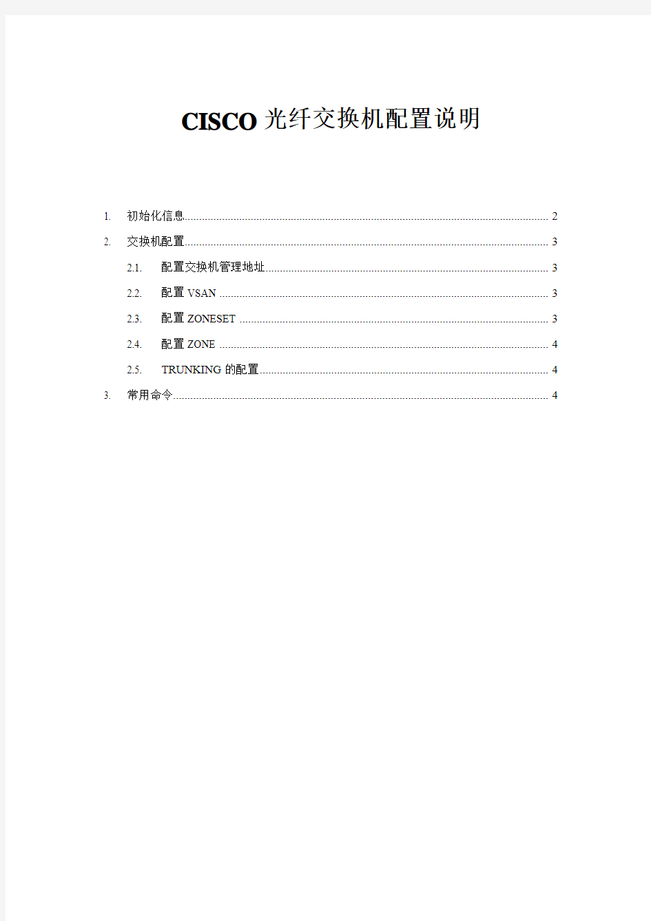
CISCO光纤交换机配置说明
1. 初始化信息 (2)
2. 交换机配置 (3)
2.1. 配置交换机管理地址 (3)
2.2. 配置VSAN (3)
2.3. 配置ZONESET (3)
2.4. 配置ZONE (4)
2.5. TRUNKING的配置 (4)
3. 常用命令 (4)
1.初始化信息
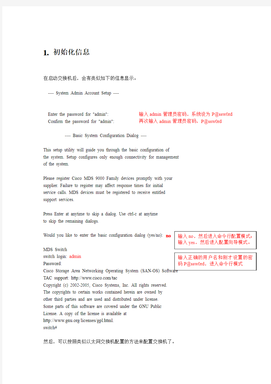
在启动交换机后,会有类似如下的信息显示:
---- System Admin Account Setup ----
Enter the password for "admin": 输入admin管理员密码,系统设为P@ssw0rd Confirm the password for "admin": 再次输入admin管理员密码,P@ssw0rd
---- Basic System Configuration Dialog ----
This setup utility will guide you through the basic configuration of
the system. Setup configures only enough connectivity for management
of the system.
Please register Cisco MDS 9000 Family devices promptly with your
supplier. Failure to register may affect response times for initial
service calls. MDS devices must be registered to receive entitled
support services.
Press Enter at anytime to skip a dialog. Use ctrl-c at anytime
to skip the remaining dialogs.
Would you like to enter the basic configuration dialog (yes/no): no
MDS Switch
switch login: admin
Password:
TAC support: https://www.360docs.net/doc/621707989.html,/tac
Copyright (c) 2002-2005, Cisco Systems, Inc. All rights reserved. The copyrights to certain works contained herein are owned by other third parties and are used and distributed under license.
Some parts of this software are covered under the GNU Public License. A copy of the license is available at
https://www.360docs.net/doc/621707989.html,/licenses/gpl.html.
switch#
然后,可以按照类似以太网交换机配置的方法来配置交换机了。
2. 交换机配置
2.1. 配置交换机管理地址
switch# config t
Enter configuration commands, one per line. End with CNTL/Z.
switch (config)# switchname switch
switch(config)#
switch(config)# interface mgmt 0
switch(config-if)# ip adress 192.168.100.108 255.255.255.0
switch(config-if)# no shutdown
interface mgmt 0 表示的是交换机的管理端口。 2.2. 配置VSAN
接下来配置VSAN
switch#config t
switch (config)#vsan database
switch(config-vsan-db)# vsan 100
switch(config-vsan-db)#end
2.3. 配置ZONESET
switch#config t switch (config)#zoneset name anhuipower vsan 100
switch (config-zoneset)#member ZONE_NAME 把ZONE 填加到该ZONESET 中
注:在交换机处于正常运行时,如果配置了新的ZONE ,并且填加到了ZONESET 中,此时需要Acitvate 才能生效,命令如下:
switch#config t
switch (config)#zoneset activate name anhuipower vsan 100
2.4. 配置ZONE
下面配置ZONE
基本命令如下:
switch#config t
switch(config)#zone name zone_name vsan 100 switch(config)#member interface fc#/# switch(config)#member interface fc#/#
交换机端口都是以fc 表示,fc1/1 表示第一个模块上的第一个端口。由于像cisco9506之类的交换机是模块化的,所以其每个端口就是fc 模块号/端口号。像cisco9120,cisco9140,不是模块化的,但其接口默认是fc1/端口号。
2.5. TRUNKING 的配置
默认情况下,交换机每个端口的TRUNKING 协议都是启用的,交换机互连的端口应工作在E mode 下,如果有两台交换机互相连接的情况,则要启用TRUNKING ,以FC1/1和FC1/2为例。
配置命令如下:
switch#config t
switch(config)# interface fc1/1 switch(config-if)# switchport mode e
switch(config)# interface fc1/2
switch(config-if)# switchport mode e
3. 常用命令
show run 显示当前配置
show zone 显示当前配置的ZONE 的信息
show zoneset 显示当前配置的ZONESET 的信息
show interface fc1/1 显示端口fc1/1信息
show zone activate 显示当前活动的ZONE 信息
show zoneset activate 显示当前活动的ZONESET 信息
copy run start 保存当前配置
思科三层交换机配置总结
思科交换机的基本配置命令学习 CISCO交换机基本配置:Console端口连接 用户模式hostname# ; 特权模式hostname(config)# ; 全局配置模式hostname(config-if)# ; 交换机口令设置: switch>enable ;进入特权模式 switch#config terminal ;进入全局配置模式 switch(config)#hostname csico ;设置交换机的主机名 switch(config)#enable secret csico1 ;设置特权加密口令 switch(config)#enable password csico8 ;设置特权非密口令 switch(config)#line console 0 ;进入控制台口 switch(config-line)#line vty 0 4 ;进入虚拟终端 switch(config-line)#login ;虚拟终端允许登录 switch(config-line)#password csico6 ;设置虚拟终端登录口令csico6 switch#exit ;返回命令 交换机VLAN创建,删除,端口属性的设置,配置trunk端口,将某端口加入vlan中,配置VTP:switch#vlan database ;进入VLAN设置 switch(vlan)#vlan 2 ;建VLAN 2 switch(vlan)#vlan 3 name vlan3 ;建VLAN 3并命名为vlan3 switch(vlan)#no vlan 2 ;删vlan 2 switch(config)#int f0/1 ;进入端口1 switch(config)#speed ? 查看speed命令的子命令 switch(config)#speed 100 设置该端口速率为100mb/s (10/auto) switch(config)#duplex ? 查看duplex的子命令 switch(config)#duplex full 设置该端口为全双工(auto/half) switch(config)#description TO_PC1 这是该端口描述为TO_PC1 switch(config-if)#switchport access vlan 2 ;当前端口加入vlan 2 switch(config-if)#switchport mode trunk ;设置为trunk模式(access模式) switch(config-if)#switchport trunk allowed vlan 1,2 ;设置允许的vlan switch(config-if)#switchport trunk encap dot1q ;设置vlan 中继 switch(config)#vtp domain vtpserver ;设置vtp域名相同 switch(config)#vtp password ;设置发vtp密码 switch(config)#vtp server ;设置vtp服务器模式 switch(config)#vtp client ;设置vtp客户机模式 交换机设置IP地址,默认网关,域名,域名服务器,配置和查看MAC地址表: switch(config)#interface vlan 1 ;进入vlan 1 switch(config-if)#ip address 192.168.1.1 255.255.255.0 ;设置IP地址 switch(config)#ip default-gateway 192.168.1.6 ;设置默认网关 switch(config)#ip domain-name https://www.360docs.net/doc/621707989.html, 设置域名 switch(config)#ip name-server 192.168.1.18 设置域名服务器 switch(config)#mac-address-table? 查看mac-address-table的子命令 switch(config)#mac-address-table aging-time 100 设置超时时间为100ms switch(config)#mac-address-table permanent 0000.0c01.bbcc f0/3 加入永久地址在f0/3端口 switch(config)#mac-address-table restricted static 0000.0c02.bbcc f0/6 f0/7 加入静态地址目标端口f0/6源端口f0/7 switch(config)#end
cisco3750三层交换机配置说明
三层交换机可以通过Telnet方式或超级终端方式连上,第一次使用的三层交换机需要进行配置,具体步骤如下: 1)、用Cisco 3750三层交换机自带的一条串行电缆将其Console口与1台维护笔记本的串口(需要知道是Com1还是Com2)相连。 2)在维护笔记本上执行以下操作:“开始→程序→附件→通讯→超级终端”,在“连接描述”对话框的名称一栏中输入“cisco3750”(此名字没有实际意义,可以随便输入),创建一个叫做"cisco3750"的新连接,点击"确定",缺省的使用COM1(根据维护计算机连接的端口选择),在"串口设置"中将波特率改为9600波特,其他参数不变,点击"确定"就可以得到三层交换机的控制台。 3)、设置结束,打开三层交换机电源,就会出现三层交换机的启动信息。这时就可以像在终端一样对三层交换机进行操作了。此时不要进行任何操作,以免破坏三层交换机的启动进程,直到三层交换机出现了: “Copyright (c) 1986-2006 by Cisco Systems, Inc. Compiled Fri 28-Jul-06 08:46 by yenanh” 回车,提示“Would you like to terminate autoinstall? [yes]:”是否要终止自动安装,输入N,进入配置页面: “--- System Configuration Dialog --- Would you like to enter the initial configuration dialog? [yes/no]:” 输入N,选择不需要,提示“Switch>00:14:58: %LINK-5-CHANGED: Interface Vlan1, changed state to administratively down”,出现“switch>”就可以输入命令进行配置。 switch >en(进入特权模式) switch #configure(进入组态模式) switch ( config ) #hostname 3750 (交换机重命名) 3750( config )#Interface vlan 1 (进入vlan1设置) 3750( config-if ) #ip add 171.100.12.1 255.255.255.0(设置vlan1的IP,连接其端口的设备必须以其IP作为网关) 3750( config-if ) #no shutdown (激活vlan1的端口)
华为三层交换机配置步骤解释
华为三层交换机配置步骤 1. 给交换机划分VLAN Vlan 是虚拟局域网的意思,它相当于一个局域网工作组。“ vlan 几”可以理解成编号为几的vlan ,比如vlan 2 就是编号为 2 的vlan ,只是一个编号而已,并不是说vlan 2 的网段一定要是 2 网段,vlan 2 的IP 地址是可以随便设置的。 下面我将三层交换机的第20个端口添加到vlan 10 里,步骤如下: A. 在交换机里添加VLAN 10 system-view (一般用缩写:sys ) [Quidway] vlan 10 (添加编号为10 的vlan ) [Quidway-vlan10] quit (一般缩写:q) B. 设置vlan 10 的IP地址为192.168.66.66 网关为255.255.255.0 [Quidway] interface vlanif 10 (interface 一般可以缩写为:int ;vlanif 也可以只写vlan ) [Quidway-vlanif10] ip address 192.168.66.66 255.255.255.0 (address 缩写add) [Quidway-vlanif10]quit C. 设定交换机上第20个端口模式为access (默认为trunk ,需在将端口划入VLAN前转为ACCES)S [Quidway] int gigabitethernet 0/0/20 (gigabitethernet :千兆以太网口) [Quidway-GigabitEthernet0/0/20] port link-type access (port :端口) [Quidway-GigabitEthernet0/0/20]quit D. 将第20个端口加入到vlan 10 里 [Quidway] vlan 10 [Quidway-vlan10] port gigabitethernet 0/0/20 (如果是多个连续端口,用XX to XX ) [Quidway-Vlan10] quit 这样就是成功的将交换机上的第20 个端口添加到了编号为10 的Vlan 里,划分VLAN就是这 4 个步骤, 2 个步骤设置vlan ,2 个步骤设置端口。现在可以用网线把交换机的第20 个端口和电脑网卡连接起来,设置网卡地址为192.168.66.XX ,网关为192.168.66.66 ,在CMD里ping192.168.66.66 可以ping 通。 2. 删除vlan A.在系统视图下,用“ undo int vlan 2 ”命令删除vlan 2 的3层口,这样vlan 2 就没有了,但是划分给vlan 2 的那些端口依然还处于vlan 2 里,这时可以将那些端口释放出来,让他们不再属于任何vlan B.在系统视图下,用“ undo vlan 2 ”命令删除2层口,这个命令可以释放那些原先划分给了vlan 2 的端口,现在它们不属于任何vlan 了。 当然,将交换机上的某个端口更换到某个vlan 里,是可以直接在vlan 视图里添加端口的。 注意:交换机上的某个端口被设置成了access 模式,且加入了一个vlan ,要想将这个端口的模式更改为trunk ,直接在端口视图里打上“ port link-type trunk ”是不行的,会出现Error: Please renew the default configurations. 这时需要先从VLAN里删除这个端口,也就是前面说的让这个端口不属于任何vlan ,才能将 这个端口设置为trunk 。 3. 通过端口进行限速 现在要对交换机上的第 2 个端口进行限速操作,让通过这个端口的下载速度不超过128KB/S 配置命令说明: Inbound:对入端口报文进行限速 Outbound:对出端口报文进行限速 sys [Quidway] int gigabitethernet 0/0/2 [Quidway-GigabitEthernet0/0/2] qos lr outbound cir 1024 cbs 204800 (1024代表1M的带宽,理论下载速度就是128KB/S,204800=1024*200 ,cbs 代表
S7506E三层交换机配置资料讲解
***************************************************************** ************* * Copyright (c) 2004-2008 Hangzhou H3C Tech. Co., Ltd. All rights reserved. * * Without the owner's prior written consent, * * no decompiling or reverse-engineering shall be allowed. * ***************************************************************** ************* Login authentication Username:admin Password: <7506E>di cur # version 5.20, Release 6305 # sysname 7506E # domain default enable system # telnet server enable # ip ttl-expires enable ip unreachables enable # port-security enable # loopback-detection enable # mirroring-group 1 local mirroring-group 2 local # switch-mode standard #
rule 0 permit ip source 192.168.128.0 0.0.15.255 rule 1 permit ip source 192.168.160.0 0.0.31.255 acl number 3011 rule 0 permit ip source 192.168.34.0 0.0.0.255 rule 1 permit ip source 192.168.37.0 0.0.0.255 rule 2 permit ip source 192.168.31.0 0.0.0.255 rule 3 permit ip source 192.168.39.0 0.0.0.255 rule 4 permit ip source 192.168.254.0 0.0.0.255 acl number 3500 # vlan 1 # vlan 2 to 2221 # vlan 2222 description wireless_guest # vlan 2223 to 2500 # vlan 3000 description test # vlan 3901 description dianxin ap # vlan 3902 description test # vlan 3985 description dhcp for temp guest meeting supervlan subvlan 36
思科交换机配置维护手册
思科交换机配置维护手册
目录
一、端口配置 1.1 配置一组端口 当使用interface range命令时有如下的规则: ?有效的组范围: o vlan从1 到4094 o fastethernet槽位/{first port} - {last port}, 槽位为0 o gigabitethernet槽位/{first port} - {last port},槽位为0 o port-channel port-channel-number - port-channel-number, port-channel号从1到64 ?端口号之间需要加入空格,如:interface range fastethernet 0/1 – 5是有效的,而interface range fastethernet 0/1-5是无效的. ?interface range命令只能配置已经存在的interface vlan ?所有在同一组的端口必须是相同类别的。
见以下例子: Switch# configure terminal Switch(config)# interface range fastethernet0/1 - 5 Switch(config-if-range)# no shutdown 以下的例子显示使用句号来配置不同类型端口的组: Switch# configure terminal Switch(config)# interface range fastethernet0/1 - 3, gigabitethernet0/1 - 2 Switch(config-if-range)# no shutdown 1.2 配置二层端口 1.2.1 配置端口速率及双工模式
Cisco3550三层交换机配置与管理
Cisco3550三层交换机配置与管理(实例) 一、3550日常管理命令 (1) 二、密码恢复 (1) 三、VLAN配置 (4) 四、SPAN监听配置 (12) 五、DHCP服务配置 (13) 1. 在3550上配置DHCP服务.. 13 2. C3550配置作为DHCP中继代理.. 15 六、流量控制 (17) 七、策略路由 (19) 一、3550日常管理命令 clear arp-cache清除ARP缓存 arp 192.168.100.22 000a.eb22.c1b5 arpa 绑定MAC和IP sh ip accounting output-packets显示统计信息(当然需要配置统计功能如:ip accounting-transits 3200) 通过IP追查交换机端口:CiscoWorks 2000 LMS网管软件的User tracking可以追查一个IP地址对应的端口。sh mac-address-table address 00e0.9102.afd0 显示这个MAC地址在哪个接口出来的;sh mac-address-table interface Fa0/20显示20端口上的MAC地址,如果只有一个,则可能连接一个电脑,如果有很多个条目,则可以连接一个交换机。sh cdp entry *显示邻居信息; 二、密码恢复 下面步骤也适用于 Cisco 层 2 系列的交换机比如 Catalyst 2900/3500XL,2940,2950/2955和层 3 系列的比如 Catalyst 3550 的密码恢复. 通过终端或带有仿真终端程序(比如 Hyper Terminal)的 PC,连接到交换机的 console 对于Catalyst 2900/3500XL 拔下交换机的电源线,然后按住交换机的 Mode 按钮,再重新插上交换机的电源线.直到端口 Port 1x 的 LED 熄灭之后释放 Mode 按钮.Catalyst
三层交换机cisco3560 ios 丢失解决笔记
周日公司电脑不能上网,经检查是三层交换机cisco3560 出问题,报错如下: ============================================= Base ethernet MAC Address: 00:19:56:d0:dd:80 Xmodem file system is available. The password-recovery mechanism is enabled. Initializing Flash... flashfs[0]: 0 files, 1 directories flashfs[0]: 0 orphaned files, 0 orphaned directories flashfs[0]: Total bytes: 32514048 flashfs[0]: Bytes used: 1024 flashfs[0]: Bytes available: 32513024 flashfs[0]: flashfs fsck took 12 seconds. ...done Initializing Flash. Boot Sector Filesystem (bs) installed, fsid: 3 done. Loading "flash:c3560-advipservicesk9-mz.122-25.SEE2.bin"...flash:c3560-advipservicesk9-mz.122-25.SEE2.bin: no such file or directory Error loading "flash:c3560-advipservicesk9-mz.122-25.SEE2.bin" Interrupt within 5 seconds to abort boot process. Boot process failed... The system is unable to boot automatically. The BOOT environment variable needs to be set to a bootable image. switch:
思科设备三层交换机的vlan间通信配置
本次主要讲解三层交换实现vlan间的相互通信: 本例配置模型图 命令行: swA配置命令: Switch>enable Switch#vlandatabase//进入vlan配置模式 % Warning: It is recommended to configure VLAN from config mode, as VLAN database mode is being deprecated. Please consult user documentation for configuring VTP/VLAN in config mode. Switch(vlan)#vlan 2 name TztA//在swA上创建vlan 2 名为TztA VLAN 2 added: Name: TztA Switch(vlan)#vlan 3 name TztB//在swA上创建vlan 3 名为TztB VLAN 3 added: Name: TztB Switch(vlan)#exit APPLY completed. Exiting.... Switch#conf t Enter configuration commands, one per line. End with CNTL/Z. Switch(config)#int f0/2 Switch(config-if)#switchport mode access
Switch(config-if)#switchport access vlan 2 //将f0/2划分给vlan 2 Switch(config-if)#exit Switch(config)#int f0/3 Switch(config-if)#switchport mode access Switch(config-if)#switchport access vlan 3 //将f0/3划分给vlan 3 Switch(config-if)#exit Switch(config)#int f0/1 Switch(config-if)#switchport mode trunk//配置与三层设备连接的f0/1为trunk模式 %LINEPROTO-5-UPDOWN: Line protocol on Interface FastEthernet0/1, changed state to down %LINEPROTO-5-UPDOWN: Line protocol on Interface FastEthernet0/1, changed state to up Switch(config-if)#switchport trunk allowed vlan all //允许所有vlan通过f0/1端口Switch(config-if)#exit Switch(config)#exit Switch# %SYS-5-CONFIG_I: Configured from console by console Switch#wr Building configuration... [OK] Switch# (三层交换机)M sw命令配置: Switch> Switch>enable Switch#vlandatabase//进入vlan配置模式 % Warning: It is recommended to configure VLAN from config mode, as VLAN database mode is being deprecated. Please consult user documentation for configuring VTP/VLAN in config mode. Switch(vlan)#vlan 2 name TztA//在Msw上创建vlan 2 名为TztA VLAN 2 added: Name: TztA
三层交换机划分个vlan实现其互相通迅
综合实验 一台思科三层交换机划分3个vlanvlan2:ip网段vlan3:ipvlan4ip各vlan之间能互相通迅.现在增加1台cisco路由想实现共享 我们的PC0、PC1处在VLAN2中,PC2、PC3处在VLAN3中,Server0处在VLAN4中。现在要使我们内网能够正常访问我们的Server0服务器,然后同时还要能够访问我们的ISP外网的WWW服务器。 三层交换机的配置 Switch#configt Switch(config)#vlan2创建VLAN2 Switch(config-vlan)#exi Switch(config)#vlan3创建VLAN3 Switch(config-vlan)#exi Switch(config)#vlan4创建VLAN4 Switch(config-vlan)#exit Switch(config)#intfa0/2将我们的fa0/2添加到VLAN2中 Switch(config-if)#swmoac
Switch(config-if)#swacvlan2 Switch(config-if)#exit Switch(config)#intfa0/3将我们的FA0/3添加到VLAN3中 Switch(config-if)#swmoac Switch(config-if)#swacvlan3 Switch(config-if)#exit Switch(config)#intfa0/4将我们的FA0/4添加到VLAN4中 Switch(config-if)#swmoac Switch(config-if)#swacvlan4 Switch(config-if)#exit Switch(config)#intvlan2给我们的VLAN2添加一个IP地址,用于不同网段之间互相访问 Switch(config-if)#ipadd Switch(config-if)#exit Switch(config)#intvlan3给我们的VLAN3添加一个IP地址 Switch(config-if)#ipadd
举例讲解H3C配置三层交换机4个步骤详细用法
举例讲解H3C配置三层交换机4个步骤详细用法 配置三层交换机的四个步骤:第一步:划分VLAN,并描述;第二步:给VLAN划网关;第三步:给VLAN指定端口;第四步:配置路由协议。 举例讲解H3C配置三层交换机4个步骤详细用法,配置三层交换机通用的四个步骤就是:划分VLAN,并描述;给VLAN划网关;给VLAN指定端口;配置路由协议;学会这几个步骤之后就能解决所有的配置三层交换机的问题。
华为三层交换机配置方法及命令
Enable //进入私有模式 Configure terminal //进入全局模式 service password-encryption //对密码进行加密 hostname Catalyst 3550-12T1 //给三层交换机定义名称 enable password 123456. //enable密码 Enable secret 654321 //enable的加密密码(应该是乱码而不是654321这样) Ip subnet-zero //允许使用全0子网(默认都是打开的) Ip name-server 172.16.8.1 172.16.8.2 //三层交换机名字Catalyst 3550-12T1对应的IP地址是172.16.8.1 Service dhcp //提供DHCP服务 ip routing //启用三层交换机上的路由模块 Exit Vtp mode server //定义VTP工作模式为sever模式 Vtp domain centervtp //定义VTP域的名称为centervtp Vlan 2 name vlan2 //定义vlan并给vlan取名(如果不取名的话,vlan2的名字应该是vlan002) Vlan 3 name vlan3 Vlan 4 name vlan4 Vlan 5 name vlan5 Vlan 6 name vlan6 Vlan 7 name vlan7 Vlan 8 name vlan8 Vlan 9 name vlan9 Exit interface Port-channel 1 //进入虚拟的以太通道组1 Interface gigabitethernet 0/1 //进入模块0上的吉比特以太口1 channel-group 1 mode on //把这个接口放到快速以太通道组1中 Interface gigabitethernet 0/2 //同上channel-group 1 mode on port-channel load-balance src-dst-ip //定义快速以太通道组的负载均衡方式(依靠源和目的IP的方式)
cisco三层交换机vlan间路由配置实例
cisco三层交换机vlan间路由配置实例 下面以cisco3560实例说明如何在一个典型的快速以太局域网中实现VLAN。所谓典型局域网就是指由一台具备三层交换功能的核心交换机接几台分支交换机(不一定具备三层交换能力)。我们假设核心交换机名称为:COM;分支交换机分别为:PAR1、PAR2、PAR3,分别通过Port 1的光线模块与核心交换机相连;并且假设VLAN名称分别为COUNTER、MARKET、MANAGING…… 需要做的工作: 1、设置VTP DOMAIN(核心、分支交换机上都设置) 2、配置中继(核心、分支交换机上都设置) 3、创建VLAN(在server上设置) 4、将交换机端口划入VLAN 5、配置三层交换 1、设置VTP DOMAIN。 VTP DOMAIN 称为管理域。 交换VTP更新信息的所有交换机必须配置为相同的管理域。如果所有的交换机都以中继线相连,那么只要在核心交换机上设置一个管理域,网络上所有的交换机都加入该域,这样管理域里所有的交换机就能够了解彼此的VLAN列表。 COM#vlan database 进入VLAN配置模式 COM(vlan)#vtp domain COM 设置VTP管理域名称 COM COM(vlan)#vtp server 设置交换机为服务器模式 PAR1#vlan database 进入VLAN配置模式 PAR1(vlan)#vtp domain COM 设置VTP管理域名称COM PAR1(vlan)#vtp Client 设置交换机为客户端模式 PAR2#vlan database 进入VLAN配置模式 PAR2(vlan)#vtp domain COM 设置VTP管理域名称COM PAR2(vlan)#vtp Client 设置交换机为客户端模式 PAR3#vlan database 进入VLAN配置模式 PAR3(vlan)#vtp domain COM 设置VTP管理域名称COM PAR3(vlan)#vtp Client 设置交换机为客户端模式 注意:这里设置核心交换机为Server模式是指允许在该交换机上创建、修改、删除VLAN 及其他一些对整个VTP域的配置参数,同步本VTP域中其他交换机传递来的最新的VLAN 信息;Client模式是指本交换机不能创建、删除、修改VLAN配置,也不能在NVRAM中存储VLAN配置,但可同步由本 VTP域中其他交换机传递来的VLAN信息。 2、配置中继为了保证管理域能够覆盖所有的分支交换机,必须配置中继。Cisco交换机能够支持任何介质作为中继线,为了实现中继可使用其特有的ISL标签。ISL (Inter-Switch Link)是一个在交换机之间、交换机与路由器之间及交换机与服务器之间传递多个VLAN信息及VLAN数据流的协议,通过在交换机直接相连的端口配置 ISL封装,即可跨越交换机进行整个网络的VLAN分配和进行配置。 在核心交换机端配置如下: COM(config)#interface gigabitEthernet 2/1 COM(config-if)#switchport COM(config-if)#switchport trunk encapsulation isl 配置中继协议 COM(config-if)#switchport mode trunk COM(config)#interface gigabitEthernet 2/2 COM(config-if)#switchport COM(config-if)#switchport trunk encapsulation isl 配置中继协议 COM(config-if)#switchport mode trunk COM(config)#interface gigabitEthernet 2/3 COM(config-if)#switchport COM(config-if)#switchport trunk encapsulation isl 配置中继协议 COM(config-if)#switchport mode trunk 在分支交换机端配置如下: PAR1(config)#interface gigabitEthernet 0/1
思科三层交换机基于环形网络的配置方案(初学者的宝典)
Cisco三层交换机网络配置方案 二vlan设置 此处的实验划分了3个vlan,一个服务器组,一个子站的主环形通道,一个子站的备环形通道。如果有多个环形通道,按照文章中的主备环形通道的配置方法增加配置即可。本片文章是以Cisco 3560编写的,配置3750与3560不一样的地方会在每一部分的开头标出,如果没有标出就是两种交换机的配置方法是一样的。如果配置的是3750(或者其他型号的可堆叠Cisco交换机),请先参阅4.6。 2.1 进入配置模式 2.1.1 进入特权模式 Switch>en 如图6所示。 图 6 2.1.2 进入配置模式 Switch#configure terminal 如图7所示。 hou 图7 进入配置模式后就可以开始划分vlan了(关于“模式”的解释请查阅4.2)。
2.2 划分vlan 2.2.1 配置交换机的名称 Switch(config)#hostname switch1 如图8所示。 图8 2.2.2 划分3个vlan switch1(config)#vlan 10 !全局配置模式下进入vlan模式并创建vlan10 switch1(config-vlan)#name commmaster !把vlan10命名为commmaster switch1(config-vlan)#vlan 20 !vlan模式下创建vlan20 switch1(config-vlan)#name commbak !把vlan20命名为commbak switch1(config-vlan)#vlan 30 !vlan模式下创建vlan30 switch1(config-vlan)# name server !把vlan30命名为server switch1na switch1(config)# 如图9所示。 图9 2.2.3 分配端口 3560端口1的名称是g0/1,3750堆叠后交换机1的端口1名称是Gi1/0/1。交换机端口的名字是什么可在特权模式(即switch1#)下用sh vlan brief查看。 2.2.3中的命令是在3560下做的测试。gi1/0/21-22 switch1(config)#interface range g0/1-2 !进入一组端口g0/1-2 switch1(config-if-range)#switchport mode access !配置这组端口的模式为接入模式(可省略) switch1(config-if-range)#switchport access vlan 10 !把该组端口接入到vlan10 switch1(config-if-range)#interface range g0/23-24 !同上 switch1(config-if-range)#switchport mode access switch1(config-if-range)#switchport access vlan 20
华为三层交换机的配置案例
配置命令
vlan 9 description link-to-pingxicentre 第二步:给VLAN 划网关 interface Vlan-interface2 description link to wenquan ip address 10.41.77.41 255.255.255.192 interface Vlan-interface3 description link to ruzhou ip address 10.41.77.105 255.255.255.192 interface Vlan-interface4 description link to xiaotun ip address 10.41.77.169 255.255.255.192 interface Vlan-interface5 description link to baofeng ip address 10.41.77.233 255.255.255.192 interface Vlan-interface6 description link to pingxi ip address 10.41.78.41 255.255.255.192 interface Vlan-interface7 description link to pingnan ip address 10.41.78.105 255.255.255.192
CISCO三层交换机VLAN配置说明
CISCO三层交换机VLAN配置说明。 实验目标: (1) 第一步实现划分4个vlan,将相应port置入到vlan号中 (2) 第二步实现4个vlan间可以相互ping (3) 第三步实现sales,tech,manage不可以相互通讯,但允许和server通讯实现过程: 第 一步划分vlan如下: Switch#vlan data Switch(vlan)#vlan 10 name sales VLAN 10 added: Name: sales Switch(vlan)#vlan 20 name tech VLAN 20 added: Name: tech Switch(vlan)#vlan 30 name manage VLAN 30 added: Name: manage
Switch(vlan)#vlan 40 name server VLAN 40 added: Name: server Switch(vlan)# Switch(config)#int range fa 0/0 - 3 Switch(config-if-range)#switchport access vlan 10 Switch(config-if-range)#exit Switch(config)#int range fa 0/4 - 6 Switch(config-if-range)#switchport access vlan 20 Switch(config-if-range)#exit Switch(config)#int range fa 0/7 - 8 Switch(config-if-range)#switchport access vlan 30 Switch(config-if-range)#exit Switch(config)#int fa 0/9 Switch(config-if)#swit Switch(config-if)#switchport acce Switch(config-if)#switchport access vlan 40 Switch(config-if)#exit
核心交换机配置规范
核心交换机配置规范 说明: 核心交换机做为网络的核心,主要运行路由走向,快速转发,为了减少配置风险和性能影响,不在上面设置控制策略。 设置规范: 1.交换机管理vlan统一使用vlan1,并配置管理ip。管理ip院外使用网段地址, 院内使用网段地址。 2.交换机命名依据规定的命名规则进行设置。级联交换机端口增加description 设置。 3.交换机密码依据我们的密码表进行设置,同时设置enabel secrect password 和telnet password.并在vty 线程上设置访问控制列表,仅允许特定的网段远程访问。 4.交换机上下级联端口设置trunk模式(cisco),统一封装协议为。交换机用户 接入端口统一设置为access模式,不允许使用switchport mode dynamic desirable自动协商模式。 5.交换机所有端口设置广播风暴抑制,抑制基准线:千兆口设置为2%,百兆 口设置为5%。 6.交换机所有密码使用密文模式,设置service password-encryption。并关闭web 访问模式no ip http server。 7.接入交换机统一设置只读通信密码snmp-server community xhpublic RO ,和 读写通信密码snmp-server community xhprivate RW。 8.汇聚交换机启用ospf路由,设置内容如下: & 设置ospf路由进程,全网统一使用100 id,每个交换机必须唯一 & 设置ospf路由状态变化,及时看到日志 & 加密认证 & & 静态路由分布到ospf路由里 9.vlan700做为ofpf路由发布vlan,并在vlan700接口上ospf路由认证:ip ospf message-digest-key 1 md5 7 cisco。 10.在每个接口vlan 上设置端口单位描述,并在非拆分vlan接口设置 no ip redirects no ip proxy-arp