51单片机外文翻译
描述
AT89C51是一个低电压,高性能CMOS8位单片机带有4K字节的可反复擦写的程序存储器(PENROM)。和128字节的存取数据存储器(RAM),这种器件采用ATMEL公司的高密度、不容易丢失存储技术生产,并且能够与MCS-51系列的单片机兼容。片内含有8位中央处理器和闪烁存储单元,有较强的功能的AT89C51单片机能够被应用到控制领域中。
功能特性
AT89C51提供以下的功能标准:4K字节闪烁存储器,128字节随机存取数据存储器,32个I/O口,2个16位定时/计数器,1个5向量两级中断结构,1个串行通信口,片内震荡器和时钟电路。另外,AT89C51还可以进行0HZ的静态逻辑操作,并支持两种软件的节电模式。闲散方式停止中央处理器的工作,能够允许随机存取数据存储器、定时/计数器、串行通信口及中断系统继续工作。掉电方式保存随机存取数据存储器中的内容,但震荡器停止工作并禁止其它所有部件的工作直到下一个复位。
引脚描述
VCC:电源电压
GND:地
P0口:
P0口是一组8位漏极开路双向I/O口,即地址/数据总线复用口。作为输出口时,每一个管脚都能够驱动8个TTL电路。当“1”被写入P0口时,每个管脚都能够作为高阻抗输入端。P0口还能够在访问外部数据存储器或程序存储器时,转换地址和数据总线复用,并在这时激活内部的上拉电阻。P0口在闪烁编程时,P0口接收指令,在程序校验时,输出指令,需要接电阻。
P1口:
P1口一个带内部上拉电阻的8位双向I/O口,P1的输出缓冲级可驱动4个TTL 电路。对端口写“1”,通过内部的电阻把端口拉到高电平,此时可作为输入口。因为
沈阳航空工业学院电子工程系毕业设计(外文翻译)
内部有电阻,某个引脚被外部信号拉低时输出一个电流。闪烁编程时和程序校验时,P1口接收低8位地址。
P2口:
P2口是一个内部带有上拉电阻的8位双向I/O口,P2的输出缓冲级可驱动4个TTL电路。对端口写“1”,通过内部的电阻把端口拉到高电平,此时,可作为输入口。因为内部有电阻,某个引脚被外部信号拉低时会输出一个电流。在访问外部程序存储器或16位地址的外部数据存储器时,P2口送出高8位地址数据。在访问8位地址的外部数据存储器时,P2口线上的内容在整个运行期间不变。闪烁编程或校验时,P2口接收高位地址和其它控制信号。
P3口:
P3口是一组带有内部电阻的8位双向I/O口,P3口输出缓冲故可驱动4个TTL 电路。对P3口写如“1”时,它们被内部电阻拉到高电平并可作为输入端时,被外部拉低的P3口将用电阻输出电流。
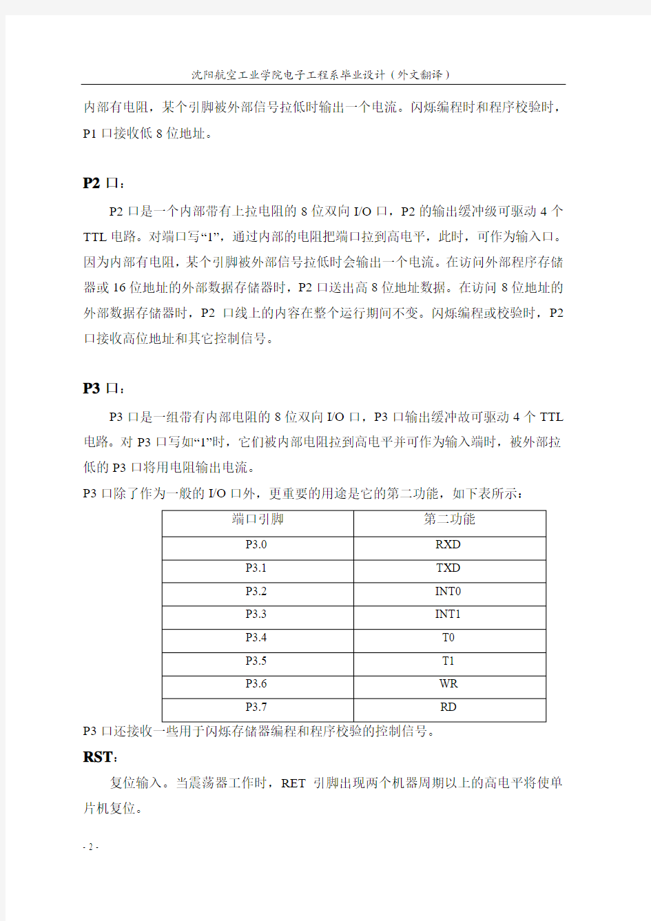
P3口除了作为一般的I/O口外,更重要的用途是它的第二功能,如下表所示:
P3
RST:
复位输入。当震荡器工作时,RET引脚出现两个机器周期以上的高电平将使单片机复位。
- 2 -
ALE/PROG:
当访问外部程序存储器或数据存储器时,ALE输出脉冲用于锁存地址的低8位字节。即使不访问外部存储器,ALE以时钟震荡频率的1/16输出固定的正脉冲信号,因此它可对输出时钟或用于定时目的。要注意的是:每当访问外部数据存储器时将跳过一个ALE脉冲时,闪烁存储器编程时,这个引脚还用于输入编程脉冲。如果必要,可对特殊寄存器区中的8EH单元的D0位置禁止ALE操作。这个位置后只有一条MOVX和MOVC指令ALE才会被应用。此外,这个引脚会微弱拉高,单片机执行外部程序时,应设置ALE无效。
PSEN:
程序储存允许输出是外部程序存储器的读选通信号,当AT89C51由外部程序存储器读取指令时,每个机器周期两次PSEN 有效,即输出两个脉冲。在此期间,当访问外部数据存储器时,这两次有效的PSEN 信号不出现。
EA/VPP:
外部访问允许。欲使中央处理器仅访问外部程序存储器,EA端必须保持低电平。需要注意的是:如果加密位LBI被编程,复位时内部会锁存EA端状态。如EA端为高电平,CPU则执行内部程序存储器中的指令。闪烁存储器编程时,该引脚加上+12V 的编程允许电压VPP,当然这必须是该器件是使用12V编程电压VPP。
XTAL1:震荡器反相放大器及内部时钟发生器的输入端。
XTAL2:震荡器反相放大器的输出端。
时钟震荡器
AT89C51中有一个用于构成内部震荡器的高增益反相放大器,引脚XTAL1和XTAL2分别是该放大器的输入端和输出端。这个放大器与作为反馈元件的片外石英晶体或陶瓷谐振器一起构成自然震荡器。外接石英晶体及电容C1,C2接在放大器的反馈回路中构成并联震荡电路。对外接电容C1,C2虽然没有十分严格的要求,但电容容量的大小会轻微影响震荡频率的高低、震荡器工作的稳定性、起振的难易程序及温度稳定性。如果使用石英晶体,我们推荐电容使用30PF±10PF,而如果使用陶瓷振荡器建议选择40PF±10PF。用户也可以采用外部时钟。采用外部时钟的电路如图示。
沈阳航空工业学院电子工程系毕业设计(外文翻译)
- 4 - 这种情况下,外部时钟脉冲接到XTAL1端,即内部时钟发生器的输入端,XTAL2则悬空。由于外部时钟信号是通过一个2分频触发器后作为内部时钟信号的,所以对外部时钟信号的占空比没有特殊要求,但最小高电平持续时间和最大的低电平持续时间应符合产品技术条件的要求。
内部振荡电路 外部振荡电路
闲散节电模式
AT89C51有两种可用软件编程的省电模式,它们是闲散模式和掉电工作模式。这两种方式是控制专用寄存器PCON 中的PD 和IDL 位来实现的。PD 是掉电模式,当PD=1时,激活掉电工作模式,单片机进入掉电工作状态。IDL 是闲散等待方式,当IDL=1,激活闲散工作状态,单片机进入睡眠状态。如需要同时进入两种工作模式,即PD 和IDL 同时为1,则先激活掉电模式。在闲散工作模式状态,中央处理器CPU 保持睡眠状态,而所有片内的外设仍保持激活状态,这种方式由软件产生。此时,片内随机存取数据存储器和所有特殊功能寄存器的内容保持不变。闲散模式可由任何允许的中断请求或硬件复位终止。终止闲散工作模式的方法有两种,一是任何一条被允许中断的事件被激活,IDL 被硬件清除,即刻终止闲散工作模式。程序会首先影响中断,进入中断服务程序,执行完中断服务程序,并紧随RETI 指令后,下一条要执行的指令就是使单片机进入闲散工作模式,那条指令后面的一条指令。二是通过硬件复位也可将闲散工作模式终止。需要注意的是:当由硬件复位来终止闲散工作模式时,中央处理器CPU 通常是从激活空闲模式那条指令的下一条开始继续执行程序的,要
完成内部复位操作,硬件复位脉冲要保持两个机器周期有效,在这种情况下,内部禁止中央处理器CPU访问片内RAM,而允许访问其他端口,为了避免可能对端口产生的意外写入:激活闲散模式的那条指令后面的一条指令不应是一条对端口或外部存储器的写入指令。
掉电模式
在掉电模式下,振荡器停止工作,进入掉电模式的指令是最后一条被执行的指令,片内RAM和特殊功能寄存器的内容在中指掉电模式前被冻结。退出掉电模式的唯一方法是硬件复位,复位后将从新定义全部特殊功能寄存器但不改变RAM中的内容,在VCC恢复到正常工作电平前,复位应无效切必须保持一定时间以使振荡器从新启动并稳定工作。
闲散和掉电模式外部引脚状态。
程序存储器的加密
AT89C51可使用对芯片上的三个加密位LB1,LB2,LB3进行编程(P)或不编程(U)得到如下表所示的功能:
当LB1被编程时,在复位期间,EA端的电平被锁存,如果单片机上电后一直没
沈阳航空工业学院电子工程系毕业设计(外文翻译)
有复位,锁存起来的初始值是一个不确定数,这个不确定数会一直保存到真正复位位置。为了使单片机正常工作,被锁存的EA电平与这个引脚当前辑电平一致。机密位只能通过整片擦除的方法清除。
Description
- 6 -
The AT89C51 is a low-power, high-performance CMOS 8-bit microcomputer with 4K bytes of Flash programmable and erasable read only memory (PEROM). The device is manufactured using Atmel’s high-density nonvolatile memory technology and is compatible with the industry-standard MCS-51 instruction set and pinout. The on-chip Flash allows the program memory to be reprogrammed in-system or by a conventional nonvolatile memory programmer. By combining a versatile 8-bit CPU with Flash on a monolithic chip, the Atmel AT89C51 is a powerful microcomputer which provides a highly-flexible and cost-effective solution to many embedded control applications. Function characteristic
The AT89C51 provides the following standard features: 4K bytes of Flash, 128 bytes of RAM, 32 I/O lines, two 16-bit timer/counters, a five vector two-level interrupt architecture, a full duplex serial port, on-chip oscillator and clock circuitry. In addition, the AT89C51 is designed with static logic for operation down to zero frequency and supports two software selectable power saving modes. The Idle Mode stops the CPU while allowing the RAM, timer/counters, serial port and interrupt system to continue functioning. The Power-down Mode saves the RAM contents but freezes the oscillator disabling all other chip functions until the next hardware reset.
Pin Description
VCC:Supply voltage.
GND:Ground.
Port 0:
Port 0 is an 8-bit open-drain bi-directional I/O port. As an output port, each pin can sink eight TTL inputs. When 1s are written to port 0 pins, the pins can be used as highimpedance inputs.Port 0 may also be configured to be the multiplexed loworder address/data bus during accesses to external program and data memory. In this mode P0 has internal pullups.Port 0 also receives the code bytes during Flash programming,and outputs the code bytes during programverification. External pullups are required during programverification.
Port 1
沈阳航空工业学院电子工程系毕业设计(外文翻译)
- 8 - Port 1 is an 8-bit bi-directional I/O port with internal pullups.The Port 1 output
buffers can sink/source four TTL inputs.When 1s are written to Port 1 pins they are pulled high by the internal pullups and can be used as inputs. As inputs,Port 1 pins that are externally being pulled low will source current (IIL) because of the internal pullups.Port 1 also receives the low-order address bytes during Flash programming and verification.
Port 2
Port 2 is an 8-bit bi-directional I/O port with internal pullups.The Port 2 output buffers can sink/source four TTL inputs.When 1s are written to Port 2 pins they are pulled high by the internal pullups and can be used as inputs. As inputs,Port 2 pins that are externally being pulled low will source current, because of the internal pullups.Port 2 emits the high-order address byte during fetches from external program memory and during accesses to external data memory that use 16-bit addresses. In this application, it uses strong internal pullupswhen emitting 1s. During accesses to external data memory that use 8-bit addresses, Port 2 emits the contents of the P2 Special Function Register.Port 2 also receives the high-order address bits and some control signals during Flash programming and verification.
Port 3
Port 3 is an 8-bit bi-directional I/O port with internal pullups.The Port 3 output buffers can sink/source four TTL inputs.When 1s are written to Port 3 pins they are pulled high by the internal pullups and can be used as inputs. As inputs,Port 3 pins that are externally being pulled low will source current (IIL) because of the pullups.Port 3 also serves the functions of various
special features of the AT89C51 as listed below:
Port 3 also receives some control signals for Flash programming and verification.
RST
Reset input. A high on this pin for two machine cycles while the oscillator is running resets the device.
ALE/PROG
Address Latch Enable output pulse for latching the low byte of the address during accesses to external memory. This pin is also the program pulse input (PROG) during Flash programming.In normal operation ALE is emitted at a constant rate of 1/6 the oscillator frequency, and may be used for external timing or clocking purposes. Note, however, that one ALE pulse is skipped during each access to external Data Memory.
If desired, ALE operation can be disabled by setting bit 0 of SFR location 8EH. With the bit set, ALE is active only during a MOVX or MOVC instruction. Otherwise, the pin is weakly pulled high. Setting the ALE-disable bit has no effect if the microcontroller is in external execution mode.
PSEN
Program Store Enable is the read strobe to external program memory.When the AT89C51 is executing code from external program memory, PSEN is activated twice each machine cycle, except that two PSEN activations are skipped during each access to external data memory.
EA/VPP
External Access Enable. EA must be strapped to GND in order to enable the device to fetch code from external program memory locations starting at 0000H up to FFFFH. Note, however, that if lock bit 1 is programmed, EA will be internally latched on reset.EA should be strapped to VCC for internal program executions.This pin also receives the 12-volt programming enable voltage(VPP) during Flash programming, for parts that require12-volt VPP.
XTAL1
Input to the inverting oscillator amplifier and input to the internal clock operating circuit.
XTAL2
沈阳航空工业学院电子工程系毕业设计(外文翻译)
- 10 - Output from the inverting oscillator amplifier.
Oscillator Characteristics
XTAL1 and XTAL2 are the input and output, respectively,of an inverting amplifier which can be configured for use as an on-chip oscillator, as shown in Figure 1.Either a quartz crystal or ceramic resonator may be used. To drive the device from an external clock source, XTAL2 should be left unconnected while XTAL1 is driven as shown in Figure 2.There are no requirements on the duty cycle of the external clock signal, since the input to the internal clocking circuitry is through a divide-by-two flip-flop, but minimum
and maximum voltage high and low time specifications must be observed.
Figure 1. Oscillator Connections Figure 2. External Clock Drive Configuration
Idle Mode
In idle mode, the CPU puts itself to sleep while all the onchip peripherals remain active. The mode is invoked by software. The content of the on-chip RAM and all the special functions registers remain unchanged during this mode. The idle mode can be terminated by any enabled interrupt or by a hardware reset.It should be noted that when idle is terminated by a hard ware reset, the device normally resumes program execution,from where it left off, up to two machine cycles before the internal reset algorithm takes control. On-chip hardware inhibits access to internal RAM in this event, but access to the port pins is not inhibited. To eliminate the possibility of an unexpected
write to a port pin when Idle is terminated by reset, the instruction following the one that invokes Idle should not be one that writes to a port pin or to external memory.
Power-down Mode
In the power-down mode, the oscillator is stopped, and the instruction that invokes power-down is the last instruction executed. The on-chip RAM and Special Function Registers retain their values until the power-down mode is terminated. The only exit from power-down is a hardware reset. Reset redefines the SFRs but does not change the on-chip RAM. The reset should not be activated before VCC is restored to its normal operating
level and must be held active long enough to allow the oscillator to restart and stabilize.
Program Memory Lock Bits
On the chip are three lock bits which can be left unprogrammed (U) or can be
programmed (P) to obtain the additional features listed in the table below.
When lock bit 1 is programmed, the logic level at the EA pin is sampled and latched during reset. If the device is powered up without a reset, the latch initializes to a random value, and holds that value until reset is activated. It is necessary that the latched value of EA be in agreement with the current logic level at that pin in order for the device to function properly.
51单片机数码管时钟程序
本人初学51,编写简单时钟程序。仅供参考学习 #include
AT89C51单片机外文翻译
AT89C51外文翻译 Description The AT89C51 is a low-power, high-performance CMOS 8-bit microcomputer with 4K bytes of Flash Programmable and Erasable Read Only Memory (PEROM). The device is manufactured using Atmel’s high density nonvolatile memory technology and is compatible with the industry standard MCS-51? instruction-set and pinout. The on-chip Flash allows the program memory to be reprogrammed in-system or by a conventional nonvolatile memory programmer. By combining a versatile 8-bit CPU with Flash on a monolithic chip, the Atmel AT89C51 is a powerful microcomputer which provides a highly flexible and cost effective solution to many embedded control applications. Features ? Compatible with MCS-51? Products ? 4K Bytes of In-System Reprogrammable Flash Memory – Endurance: 1,000 Write/Erase Cycles ? Fully Static Operation: 0 Hz to 24 MHz ? Three-Level Program Memory Lock ? 128 x 8-Bit Internal RAM ? 32 Programmable I/O Lines ? Two 16-Bit Timer/Counters ? Six Interrupt Sources ? Programmable Serial Channel ? Low Power Idle and Power Down Modes The AT89C51 provides the following standard features: 4K bytes of Flash,128 bytes of RAM, 32 I/O lines, two 16-bit timer/counters, a five vector two-level interrupt architecture, a full duplex serial port, on-chip oscillator and clock circuitry. In addition, the AT89C51 is designed with static logic for operation down to zero frequency and supports two software selectable power saving modes. The Idle Mode stops the CPU while allowing the RAM, timer/counters, serial port and interrupt system to continue functioning. The Power-down Mode saves the RAM contents but freezes the oscillator disabling all other chip functions until the next hardware reset.
51单片机控制4个数码管显示
. //使用AT89c51单片机控制四个数码管动态显示0-9999 ,12MHz #include
51单片机-数码管
51单片机-数码管 共阴极是指所有发光二极管阴极连接在一起,这个共阴极可以用来做片选。 如图,这里有8个发光二极管,到底哪个亮需要进行片选。段选:8 段数码管 每一段的控制段叫段选位选:就是进行哪个8 段数码管亮的选择TX-1C 使用两 片锁存器74HC573 实现位选和段选这里的D0”7是连在单片机的I/O 口上,当 为高电平时,Q 与D 中的数据一致,遇到负跳变沿时Q 中的数据保持住,D 中 的数据即使变化也不会影响Q。MCUVersion2 使用的是74HC245 和38 译码器 74HC13874HC245 有一个缓冲和驱动的作用,这样可以使led 显示的更加稳定, 数码管显示分动态显示和静态显示,每个数码管的状态都是被不断更新的,利 用的人的视觉暂留,使看上去数值保持在一个固定的位置上,人的视觉是有延 续性的,当一个东西不断变化时,变化的时间小于人眼的视觉暂留时间的话, 人的眼睛会以为这个东西是连续的。静态显示是一幅画面放在那看上去是不动 的而它确实是不动的。动态扫描显示即轮流向各位数码管送出字型码和相应位 选,利用发光管的余晖和视觉暂留作用,使人的感觉好像各位数码管同时都在 显示。静态显示:数码管从左向右依次点亮: #include <reg52.h>void delay(){ int i,j; for(i = 0; i <0xff; i++) for(j = 0; j <0xff; j++) ;} unsigned int code duan[]={0x3F,0x06,0x5B,0x4F,0x66,0x6D,0x7D,0x07};unsigned int code wei[]={ 0xf8,0xf9,0xfa,0xfb,0xfc,0xfd,0xfe,0xff};void main(){ while(1){ int i; P2 = 0x39; for(i = 0; i <8; i++){ P2 = duan[ i]; P1 = wei[ i]; delay(); } } } 想让哪个 数码管亮多少就亮多少:tips:感谢大家的阅读,本文由我司收集整编。仅供参阅!
51单片机课程设计
课程设计说明书
课程设计名称
专
业
班
级
学
号
学生姓名
指导教师
单片机原理及应用课程设计 电子信息工程 140405 20141329 李延琦 胡黄水
2016 年 12 月 26 日
课程设计任务书
课程设计 题目
酒精测试仪
起止日期
2016 年 12 月 26 日— 2017 年 1 月 6 日
设计地点
计算机科学与工程学 院单片机实验室 3409
设计任务及日程安排: 设计任务:分两部分: (一)、设计实现类:进行软、硬件设计,并上机编程、联线、调试、 实现; 1.电子钟的设计 2.交通灯的设计 3.温度计的设计 4.点阵显示 5.电机调速 6.电子音乐发声(自己选曲) 7.键盘液晶显示系统 (二)、应用系统设计类:不须上机,查资料完成软、硬件设计画图。 查资料选定题目。 说明:第 1--7 题任选其二即可。(二)里题目自拟。 日程安排: 本次设计共二周时间,日程安排如下: 第 1 天:查阅资料,确定题目。 第 2--4 天:进实验室做实验,连接硬件并编写程序作相关的模块实验。 第 5--7 天:编写程序,并调试通过。观察及总结硬件实验现象和结果。 第 8--9 天:整理资料,撰写课程设计报告,准备答辩。 第 10 天:上交课程设计报告,答辩。 设计报告要求:
1. 设计报告里有两个内容,自选题目内容+附录(实验内容),每 位同学独立完成。 2. 自选题目不须上机实现,要求能正确完成硬件电路和软件程序 设计。内容包括: 1) 设计题目、任务与要求 2)硬件框图与电路图 3) 软件及流程图 (a)主要模块流程图 (b)源程序清单与注释 4) 总结 5) 参考资料 6)附录 实验上机调试内容
注:此任务书由指导教师在课程设计前填写,发给学生做为本门课程设计 的依据。
基于51单片机的数码管简易计算器
基于51/52单片机的简易计算器制作 11级自动化2班 王栎斐宋为为闫巨东 一、题目利用单片机芯片STC89C52、四位八段共阳数码管及已制作好的电路板等器件设计制作一个计算器。 二、任务与要求要求计算器能实现加减乘除四种运算 具体如下 1. 加法:四位整数加法计算结果若超过八位则显示计算错误 2. 减法:四位整数减法计算结果若超过八位则显示计算错误 3. 乘法:多位整数乘法计算结果若超过四位则显示计算错误 4. 除法:整数除法 5. 有清除功能 三、课程设计简述 总体设计思路简述 1.按照系统设计的功能的要求 初步确定设计系统由主控模块、显示模块、键扫描接口 电路共三个模块组成。主控芯片使用STC89C52单片机。 2.键盘电路采用4*4矩阵键盘电路。 3.显示模块采用共阳极数码管构成。 四、硬件电路 五、软件编程部份 #include
#define uchar unsigned char #define uint unsigned int //uchar code num[]={0x3f,0x06,0x5b,0x4f,0x66,0x6d,0x7d,0x07,0x7f,0x6f,0x00,0x40}; //共阴极 // 0 1 2 3 4 5 6 7 8 9 熄灭- //uchar code loc[]={0xff,0xfe,0xfd,0xfb,0xf7}; //uchar code ero[]={0x79,0x50,0x5c}; uchar code num[]={0xc0,0xf9,0xa4,0xb0,0x99,0x92,0x82,0xf8,0x80,0x90,0xff,0x40}; //共阳极 uchar code loc[]={0x00,0x80,0x40,0x20,0x10}; uchar code ero[]={~0x79,~0x50,~0x5c}; uint n=0,n1=0,n2=0; //赋初值 uchar flag=0; //计算类型选择关键字 void delay(int t); void display(int n); void error(); main() { while(1) { uchar temp; //第一行检测 P3=0xfe; temp=P3; temp=temp&0xf0; if(temp!=0xf0) { delay(10); temp=P3; temp=temp&0xfe; if(temp!=0xfe) { temp=P3; switch(temp) { case 0xee:n1=0;n2=0;n=0;flag=0;break;
51单片机外文文献
The Introduction of AT89C51 Description The AT89C51 is a low-power, high-performance CMOS 8-bit microcomputer with 4K bytes of Flash programmable and erasable read only memory (PEROM). The device is manufactured using Atmel’s high-density nonvolatile memory technology and is compatible with the industry-standard MCS-51 instruction set. The on-chip Flash allows the program memory to be reprogrammed in-system or by a conventional nonvolatile memory programmer. By combining a versatile 8-bit CPU with Flash on a monolithic chip, the Atmel AT89C51 is a powerful microcomputer which provides a highly-flexible and cost-effective solution to many embedded control applications. Function characteristic The AT89C51 provides the following standard features: 4K bytes of Flash, 128 bytes of RAM, 32 I/O lines, two 16-bit timer/counters, one 5 vector two-level interrupt architecture, a full duplex serial port, one-chip oscillator and clock circuitry. In addition, the AT89C51 is designed with static logic for operation down to zero frequency and supports two software selectable power saving modes. The Idle Mode stops the CPU while allowing the RAM, timer/counters, serial port and interrupt system to continue functioning. The Power-down Mode saves the RAM contents but freezes the oscillator disabling all other chip functions until the next hardware reset. Pin Description VCC:Supply voltage. GND:Ground.
51单片机-八段数码管显示
实验一八段数码管显示 1、实验目的: (1)了解数码管动态显示的原理。 (2)了解74LS164扩展端口的方法。 2、实验要求: 利用实验仪提供的显示电路,动态显示一行数据. 3、实验电路图 LED1LED2LED3LED4LED5LED6 4、实验器材: (1)超想-3000TB综合实验仪 1 台 (2)超想3000仿真器 1 台 (3)计算机 1 台
5、实验连线 无 6、实验说明: (1)本实验仪提供了8段码LED 显示电路,学生只要按地址输出相应数据,就可以实现对显示器的控制。显示共有6位,用动态方式显示。8段数码管是由8155的PB0、PB1经74LS164“串转并”后输出得到。6位位码由8155的PA0口输出,经Ua2003反向驱动后,选择相应显示位。 74LS164是串行输入并行输出转换电路,串行输入的数据位由8155的PB0控制,时钟位由8155的PB1控制输出。写程序时,只要向数据位地址输出数据,然后向时钟位地址输出一高一低两个电平就可以将数据位移到74LS164中,并且实现移位。向显示位选通地址输出高电平就可以点亮相应的显示位。 本实验仪中数据位输出地址为0e102H ,时钟位输出地址为0e102H ,位选通输出地址为 0e101H 。本实验涉及到了8155 I0/RAM 扩展芯片的工作原理以及74LS164器件的工作原理。 (2)七段数码管的字型代码表 显示字形 g f e d c b a 段码 0 0 1 1 1 1 1 1 3fh 1 0 0 0 0 1 1 0 06h 2 1 0 1 1 0 1 1 6bh 3 1 0 0 1 1 1 1 4fh 4 1 1 0 0 1 1 0 66h 5 1 1 0 1 1 0 1 6dh 6 1 1 1 1 1 0 1 7dh 7 0 0 0 0 1 1 1 07h 8 1 1 1 1 1 1 1 7fh 9 1 1 0 1 1 1 1 6fh A 1 1 1 0 1 1 1 77h B 1 1 1 1 1 0 0 7ch C 0 1 1 1 0 0 1 39h D 1 0 1 1 1 1 0 5eh E 1 1 1 1 0 0 1 79h F 1 1 1 1 71h a b c d e f g dp
51单片机课程设计 AD转换
课程设计报告 华中师范大学武汉传媒学院 传媒技术学院 电子信息工程2011 仅发布百度文库,版权所有.
AD转换 要求: A.使用单片机实现AD转换 B.可以实现一位AD转换,并显示(保留4位数字)设计框图:
方案设计: AD转换时单片机设计比较重要的实验。模数转换芯片种类多,可以满足不同用途和不同精度功耗等。 外部模拟量选择的是简单的电位器,通过控制电位器来改变模拟电压。显示电压值采用一般的四位七段数码管。而AD转换芯片采用使用最广的ADC0809 ADC0809芯片有28条引脚,采用双列直插式封装,如图所示。 下面说明各引脚功能: ?IN0~IN7:8路模拟量输入端。 ?2-1~2-8:8位数字量输出端。 ?ADDA、ADDB、ADDC:3位地址输入线,用于选通8路模拟输入中的一路。?ALE:地址锁存允许信号,输入端,高电平有效。 ?START: A/D转换启动脉冲输入端,输入一个正脉冲(至少100ns宽)使其启动(脉冲上升沿使0809复位,下降沿启动A/D转换)。 ?EOC: A/D转换结束信号,输出端,当A/D转换结束时,此端输出一个高电平(转换期间一直为低电平)。 ?OE:数据输出允许信号,输入端,高电平有效。当A/D转换结束时,此端输入一个高电平,才能打开输出三态门,输出数字量。 ?CLK:时钟脉冲输入端。要求时钟频率不高于640KHz。
?REF(+)、REF(-):基准电压。 ?Vcc:电源,单一+5V。 ?GND:地 工作原理: 首先输入3位地址,并使ALE=1,将地址存入地址锁存器中。此地址经译码选通8路模拟输入之一到比较器。START上升沿将逐次逼近寄存器复位。下降沿启动A/D转换,之后EOC输出信号变低,指示转换正在进行。直到A/D转换完成,EOC 变为高电平,指示A/D转换结束,结果数据已存入锁存器,这个信号可用作中断申请。当OE输入高电平时,输出三态门打开,转换结果的数字量输出到数据总线上。 本次实验采用中断方式 把表明转换完成的状态信号(EOC)作为中断请求信号,以中断方式进行数据传送。 不管使用上述哪种方式,只要一旦确定转换完成,即可通过指令进行数据传送。 首先送出口地址并以信号有效时,OE信号即有效,把转换数据送上数据总线,供单片机接受。 采用中断可以减轻单片机负担。并可以使程序有更多的空间作二次开发。
单片机外文翻译--STC89C52处理芯片
外文资料翻译 STC89C52 processi ng chip Prime features: With MCS - 51 SCM product compatibility, 8K bytes in the system programmable Flash memory, 1000 times CaXie cycle, the static operation: 0Hz ~ 33Hz, triple encryption program memory, 32 programmed I/O port, three 16 timer/counter, the eight uninterrupted dual-career UART serial passage, low power consumption, leisure and fall after fall electric power mode can be awakened and continuous watchdog timer and double-number poin ter, power ide ntifier. Efficacy: characteristics STC89C52 is one kind of low power consumption, high CMOS8 bit micro-co ntroller, 8K in system programmable Flash memory. Use high-de nsity nonv olatile storage tech no logy, and in dustrial 80C51 product in structi on and pin fully compatible. The Flash memory chips allows programs in the system, also suitable for programmable conventional programming. In a single chip, have clever 8 bits CPU and on li ne system programmable Flash, in crease STC89C52 for many embedded control system to provide high vigorous application and useful solutions. STC89C52 has following standard efficacy: 8k byte Flash RAM, 256 bytes, 32 I/O port, the watchdog timer, two, three pointer numerical 16 timer/counter, a 6 vector level 2 continuous structure, the serial port, working within crystals and horological circuit. In addition, 0Hz AT89S52 can drop to the static logic operation, support two software can choose power saving mode. Idle mode, the CPU to stop working, and allows the RAM, timer/c oun ters, serial, continu ous to work. Protectio n asa na patter n, RAM content is survival, vibrators frozen, SCM, until all the work under a continuous or hardware reset. 8-bit microcontrollers 8K bytes in the system programmable Flash AT89S52 devices. Mouth: P0 P0 mouth is a two-way ope n drain I/O. As export, each can drive eight TTL logic level. For P0 port to write "1", foot as the high impeda nee in put. When access to exter nal programs and nu merical memory, also known as
基于51单片机的LED数码管动态显示
基于51单片机的LED数码管动态显示 LED数码管动态显示就是一位一位地轮流点亮各位数码管,对于每一位LED数码管来说,每隔一段时间点亮一次,利用人眼的“视觉暂留"效应,采用循环扫描的方式,分时轮流选通各数码管的公共端,使数码管轮流导通显示。当扫描速度达到一定程度时,人眼就分辨不出来了。尽管实际上各位数码管并非同时点亮,但只要扫描的速度足够快,给人的印象就是一组稳定的显示数据,认为各数码管是同时发光的。若数码管的位数不大于8位时,只需两个8位I/O口。 1 硬件设计 利用51单片机的P0口输出段码,P2口输出位码,其电路原理图如下所示。 在桌面上双击图标,打开ISIS 7 Professional窗口(本人使用的是v7.4 SP3中文版)。单击菜单命令“文件”→“新建设计”,选择DEFAULT模板,保存文件名为“DT.DSN”。在器件选择按钮中单击
“P”按钮,或执行菜单命令“库”→“拾取元件/符号”,添加如下表所示的元件。 51单片机AT89C51 一片 晶体CRYSTAL 12MHz 一只 瓷片电容CAP 22pF 二只 电解电容CAP-ELEC 10uF 一只 电阻RES 10K 一只 电阻RES 4.7K 四只 双列电阻网络Rx8 300R(Ω) 一只 四位七段数码管7SEG-MPX4-CA 一只 三极管PNP 四只 若用Proteus软件进行仿真,则上图中的晶振和复位电路以及U1的31脚,都可以不画,它们都是默认的。 在ISIS原理图编辑窗口中放置元件,再单击工具箱中元件终端图标,在对象选择器中单击POWER 和GROUND放置电源和地。放置好元件后,布好线。左键双击各元件,设置相应元件参数,完成电路图的设计。 2 软件设计 LED数码管动态显示是一位一位地轮流点亮各位数码管的,因此要考虑每一位点亮的保持时间和间隔时间。保持时间太短,则发光太弱而人眼无法看清;时间太长,则间隔时间也将太长(假设N位,则间隔时间=保持时间X(N-1)),使人眼看到的数字闪烁。在程序中要合理的选择合适的保持时间和间隔时间。而循环次数则正比于显示的变化速度。 LED数码管动态显示的流程如下所示。
51单片机课程设计实验报告
51单片机课程设计报告 学院: 专业班级: 姓名: 指导教师: 设计时间:
51单片机课程设计 一、设计任务与要求 1.任务:制作并调试51单片机学习板 2.要求: (1)了解并能识别学习板上的各种元器件,会读元器件标示; (2)会看电路原理图; (3)制作51单片机学习板; (4)学会使用Keil C软件下载调试程序; 用调试程序将51单片机学习板调试成功。 二、总原理图及元器件清单 1.总原理图 2.元件清单 三、模块电路分析 1. 最小系统: 单片机最小系统电路分为振荡电路和复位电路, 振荡电路选用12MHz 高精度晶振, 振荡电容选用22p和30p 独石电容;
图 1 图 2 复位电路使用RC 电路,使用普通的电解电容与金属膜电阻即可; 图 3 当单片机上电瞬间由于电容电压不能突变会使电容两边的电位相同,此时RST 为高电平,之后随着时间推移电源负极通过电阻对电容放电,放完电时RST 为低电平。正常工作为低电平,高电平复位。 2. 显示模块: 分析发光二极管显示电路: 图 4 发光二极管显示电路分析:它是半导体二极管的一种,可以把电能转化成光能,常简写为
LED。发光二极管与普通二极管一样是由一个PN结组成,也具有单向导电性。当给发光二极管加上正向电压后,产生自发辐射的荧光。图中一共有五个发光二极管 其中一个为电源指示灯,当学习板通电时会发光以指示状态。其余四个为功能状态指示灯,实际作用与学习板有关 分析数码管显示电路 图 5 数码管显示电路分析:数码管按段数分为七段数码管和八段数码管,图中所用为八段数码管(比七段管多了一个小数点显示位),按发光二极管单元连接方式分为共阳极数码管和共阴极数码管。共阳数码管是指将所有发光二极管的阳极接到一起形成公共阳极(COM)的数码管.共阴数码管是指将所有发光二极管的阴极接到一起形成公共阴极(COM)的数码管。数码管主要用来显示经电路板处理后的程序的运行结果。图中使用了八个八段数码管,可以显示八个0-15的数字。使用数码管可以直观的得到程序运行所显示的结果.也可以显示预置在学习板上的程序,主要通过16个开关来控制。 四、硬件调试 1、是否短路 用万用表检查P2两端是短路。电阻为0,则短路,电阻为一适值,电路正常。 2、焊接顺序 焊接的顺序很重要,按功能划分的器件进行焊接,顺序是功能部件的焊接--调试--另一功能部件的焊接,这样容易找到问题的所在。 3、器件功能 1)检查原理图连接是否正确 2)检查原理图与PCB图是否一致 3)检查原理图与器件的DA TASHEET上引脚是否一致 4)用万用表检查是否有虚焊,引脚短路现象 5)查询器件的DA TASHEET,分析一下时序是否一致,同时分析一下命令字是否正确 6)通过示波器对芯片各个引脚进行检查,检查地址线是否有信号的 7)飞线。用别的的口线进行控制,看看能不能对其进行正常操作,多试验,
外文翻译---51系列单片机的结构和功能
外文翻译---51系列单片机的结构和功能
外文资料翻译 英文原文: Structure and function of the MCS-51 series Structure and function of the MCS-51 series one-chip computer MCS-51 is a name of a piece of one-chip computer series which Intel Company produces. This company introduced 8 top-grade one-chip computers of MCS-51 series in 1980 after introducing 8 one-chip computers of MCS-48 series in 1976. It belong to a lot of kinds this line of one-chip computer the chips have such as 8051, 8031, 8751, 80C51BH, 80C31BH,etc., their basic composition, basic performance and instruction system are all the same. 8051 daily representatives- 51 serial one-chip computers . An one-chip computer system is made up of several following parts: (1) One microprocessor of 8 (CPU). (2) At slice data memory RAM (128B/256B),it use not depositing not can reading /data that write, such as result not middle of operation, final result and data wanted to show, etc. (3) Procedure memory ROM/EPROM (4KB/8KB ), is used to preserve the procedure , some initial data and form in slice. But does not take ROM/EPROM within some one-chip computers, such as 8031 , 8032, 80C ,etc.. (4) Four 8 run side by side I/O interface P0 four P3, each mouth can use as introduction, may use as exporting too. (5) Two timer / counter, each timer / counter may set up and count in the way, used to count to the external incident, can set up into a timing way too, and can according to count or result of timing realize the control of the computer. (6) Five cut off cutting off the control (universal asynchronous receiver/transmitter (UART) ), is it realize one-chip computer or one-chip computer and serial communication of computer to use for. (8) Stretch oscillator and clock produce circuit, quartz crystal finely tune electric capacity need outer. Allow oscillation frequency as 12 megahertz now at most. Every the above-mentioned part was joined through the inside data bus .Among them, CPU is a core of the one-chip computer, it is the control of the computer and command center, made up of such parts as arithmetic unit and controller , etc.. The arithmetic unit can carry on 8 persons of arithmetic operation and unit ALU of logic operation while including one, the 1 storing devices temporarily of 8, storing device 2 temporarily, 8's accumulation device ACC, register B and procedure state register PSW, etc. Person who accumulate ACC count by 2 input ends entered of checking etc. temporarily as one operation often, come from person who store 1 operation is it is it make operation to go on to count temporarily , operation result and loop back ACC with another one. In addition, ACC is often regarded as the transfer station of data transmission on 8051 inside. The same as general microprocessor, it is the busiest register. Help remembering that agreeing with a expresses in the order. The controller includes the procedure counter, the order is deposited, the
51单片机课程设计报告
成绩: 单片机原理及应用课程设计 课程名<<单片机原理及应用>> 学部机械与电子信息工程学部 专业移动通信技术 学号 姓名 指导教师 日期
一、设计任务与要求 1.任务:制作并调试51单片机学习板 2.要求: (1)了解并能识别学习板上的各种元器件,会读元器件标示; (2)会看电路原理图; (3)制作51单片机学习板; (4)学会使用Keil C软件下载调试程序; 用调试程序将51单片机学习板调试成功。 二、实验内容 (5)AT89S52芯片工作电路,利用晶振提供控制信号。 (6)10引脚下载口与A T89S52芯片相关引脚相连完成下载电路。 (7)8个10K电阻与AT89S52芯片P0口相连,利用上拉电阻组成上拉电路。 (8)使用开关与5.1K电阻连成外部中断0、1电路和复位电路。 (9)利用16个开关做成键盘,实现输入号对已编程的AT89S52芯片的控制并通过数码管显示0--F。 (10)用2片74HC573N具有锁存功能芯片与8个数码管相连,通过编程的A T89S52位选和段选实现输出信号的显示功能。 (11)使用74HC573N锁存功能结合ULN2003AG芯片8非门芯片和74HC04N6非门芯片与4个2N5551三极管实现对步进电机的控制,和控制步进电机的信号结 合LED输出显示的功能。 (12)6、利用1片74HC573N芯片与8个共阴极LED实现跑马灯功能。 三、总原理图 1.总原理图
四、硬件调试 1、是否短路 用万用表检查P2两端是短路。电阻为0,则短路,电阻为一适值,电路正常。 2、焊接顺序 焊接的顺序很重要,按功能划分的器件进行焊接,顺序是功能部件的焊接--调试-- 另一功能部件的焊接,这样容易找到问题的所在。 3、器件功能 1)检查原理图连接是否正确 2)检查原理图与PCB图是否一致 3)检查原理图与器件的DATASHEET上引脚是否一致 4)用万用表检查是否有虚焊,引脚短路现象 5)查询器件的DATASHEET,分析一下时序是否一致,同时分析一下命令字是否正确 6)通过示波器对芯片各个引脚进行检查,检查地址线是否有信号的 7)飞线。用别的的口线进行控制,看看能不能对其进行正常操作,多试验,才能找到问题出现在什么地方。 五、软件调试 1、设置硬件仿真环境 设置硬件仿真环境的具体操作步骤如下: 首先,点击所建工程:Project菜单中的Options for Target…Targer 1?,出现工程的配置窗口,
51单片机应用设计课后答案
第一章单片机概述 1.2除了单片机这一名称之外,单片机还可称为(微控制器)和(嵌入式控制器)。 1.3单片机与普通计算机的不同之处在于其将(微处理器)、(存储器)和(各种输入输出接 口)三部分集成于一块芯片上。 4、单片机的发展大致分为哪几个阶段? 答:单片机的发展历史可分为四个阶段: 第一阶段(1974年----1976年):单片机初级阶段。 第二阶段(1976年----1978年):低性能单片机阶段。 第三阶段(1978年----现在):高性能单片机阶段。 第四阶段(1982年----现在):8位单片机巩固发展及16位单片机、32位单片机推出阶段 1.5单片机根据其基本操作处理的位数可分为哪几种类型? 答:单片机根据其基本操作处理的位数可分为:1位单片机、4位单片机、8位单片机、16位 单片机和32位单片机。 1.6 MCS-51系列单片机的基本芯片分别为哪几种?它们的差别是什么? 答:基本芯片为8031、8051、8751。 8031内部包括1个8位cpu、128BRAM,21个特殊功能寄存器(SFR)、4个8位并行I/O 口、1 个全双工串行口,2个16位定时器/计数器,但片内无程序存储器,需外扩EPROM芯片。 8051是在8031的基础上,片内又集成有4KBROM,作为程序存储器,是1个程序不超过4KB 的小系统。 8751是在8031的基础上,增加了4KB的EPROM,它构成了1个程序小于4KB的小系统。用户可以将程序固化在EPROM中,可以反复修改程序。 1.7 MCS-51系列单片机与80C51系列单片机的异同点是什么? 答:共同点为它们的指令系统相互兼容。不同点在于MCS-51是基本型,而80C51采用CMOS 工艺,功耗很低,有两种掉电工作方式,一种是CPU停止工作,其它部分仍继续工作;另 一种是,除片内RAM继续保持数据外,其它部分都停止工作。 1.8 8051与8751的区别是(C) (A、内部数据存储单元数目的不同(B、内部数据存储器的类型不同 (C)内部程序存储器的类型不同(D、内部的寄存器的数目不同 1.9在家用电器中使用单片机应属于微型计算机的(B) (A、辅助设计应用(B、测量、控制应用(C)数值计算应用(D)数据处理应用 1.10说明单片机主要应用在哪些领域? 答:单片机主要运用领域为:工业自动化;智能仪器仪表;消费类电子产品;通信方面;武 器装备;终端及外部设备控制;多机分布式系统。 第二章MCS-51单片机的硬件结构 2.1 MCS-51单片机的片内都集成了哪些功能部件?各个功能部件的最主要的功能是什么?答:功能部件如下:微处理器(CPU);数据存储器(RAM );程序存储器(ROM/EPROM , 8031没有此部件),4个8位并行I/O 口(P0口、P1 口、P2口、P3口);1个全双工的串行口;2个16位定时器/计数器;中断系统;21个特殊功能寄存器(SFR)。 各部件功能:CPU (微处理器)包括了运算器和控制器两大部分,还增加了面向控制的处理 功能,不仅可处理字节数据,还可以进行位变量的处理;数据存储器(RAM、片内为128B (52系列的为256B),片外最多可外扩64KB。数据存储器来存储单片机运行期间的工作变 量、运算的中间结果、数据暂存和缓冲、标志位等;程序存储器(ROM/EPROM、用来存储