砂带机制作方法与图纸

OK folks, there hasn’t been a grinder tutorial for sometime now, whenever I post one of mine up they get a lot of interest so thought I would show you how to make one of these
It’s basically a KMG clone uses 1600 to 2000 x 50 belts and the great thing about these machines is there adaptability. It’s very simple to have a platen grinding head, contact wheel or small wheel attachment
A general overview of the construction is, all welded main frame, sliding type tool arm lockable with a single fastener, single knob tracking system with variable spring tension, main drive pulley is 100mm Dia x 55mm wide
Tracking pulley is 80 mm Dia ‘crowned’ x 55mm wide platen rollers 45mm Dia x 50mm wide. This will be run with a 2hp motor and three speed drive.
For those of you that have seen one of these in action you’ll know just how good they really are!! As for the plan, their isn’t one, I’ve made quite a few of these now and the majo r problem that I have is obtaining a regular supply of steel the sizes that I want, so I make them with the steel that’s available to me,
The good news is that all the dimensions given are quite adaptable; as long as you stick to very similar sizes you sho uldn’t go wrong.
I will start of by making the main frame (the blue bit) first, It’s an all welded construction making for a very rigid frame, the disadvantage is you will need to be very careful in getting it clamped up square and spot on before you weld, as I’m sure you will appreciate it’s a real pain having to grind off welds when you get them wrong!
I intend to complete the grinder right through to fitting the motor and running it.
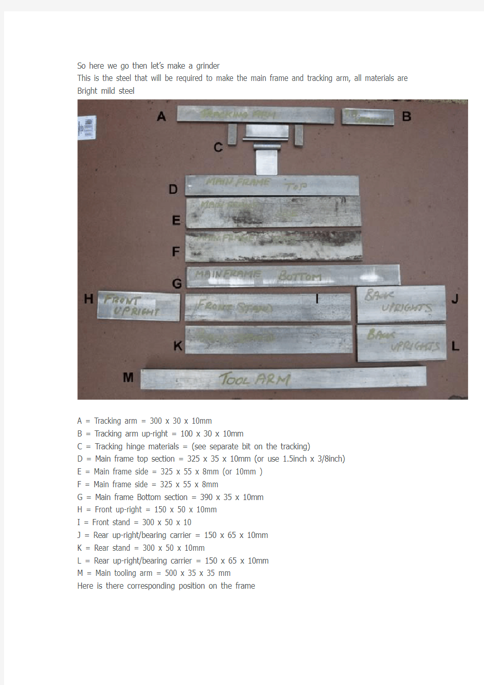
So here we go then let’s make a grinder
This is the steel that will be required to make the main frame and tracking arm, all materials are Bright mild steel
A = Tracking arm = 300 x 30 x 10mm
B = Tracking arm up-right = 100 x 30 x 10mm
C = Tracking hinge materials = (see separate bit on the tracking)
D = Main frame top section = 325 x 35 x 10mm (or use 1.5inch x 3/8inch)
E = Main frame side = 325 x 55 x 8mm (or 10mm )
F = Main frame side = 325 x 55 x 8mm
G = Main frame Bottom section = 390 x 35 x 10mm
H = Front up-right = 150 x 50 x 10mm
I = Front stand = 300 x 50 x 10
J = Rear up-right/bearing carrier = 150 x 65 x 10mm
K = Rear stand = 300 x 50 x 10mm
L = Rear up-right/bearing carrier = 150 x 65 x 10mm
M = Main tooling arm = 500 x 35 x 35 mm
Here is there corresponding position on the frame
Now before we get the MIG out we need to drill a few holes
I will be using SFT20 bearing for the main drive pulley, so we have to drill the up-rights (items J and L 150x65x10) measure down from the top, 25mm (this is where the first 11.5mm hole goes), mark the centre line, and drill to suit the bearings, make the main mounting holes 11.5mm and the centre hole 25mm that way it allows for a bit of adjustment.
The tracking arm up-right (item B 100x30x10) mark the centre and measure down 15mm from the top drill (8.5mm) and tap M10
The two stands (items I and K 300x50x10) mark the centre line measure in 15mm from each end drill 6mm from one end only measure in 50mm and drill 10mm (this is for the motor mounting frame, not shown yet)
Right now with that successfully done we move onto the next bit, this is where we get serious, we now have to make a box around the main tool arm, to make this as easy as possible we will use the tool arm as a jig,
You will need several clamps and bits of metal to get this right, place the top and bottom box sections opposite each other on the tool arm, we will need a bit of clearance here so insert a couple of thin (1mm) bits of steel between the tool arm and bottom section clamp into place, fit
the sides, position so the top is level and clamp into place, you should have the lower section with 65mm protruding out from the back ( G on the third picture down)
When happy with your clamping, tack weld in several places, remove clamps check for square and alignment and that the tool arm slides in and out easily if your happy with it weld it up, then grind and clean up the welds on the top section,
Now we will fit the rear up-rights (item J and L) when I make these I always drill as a pair, when it comes to welding them into place they need to be spaced at 38mm apart on the inside edge this is to allow one of the drive bearings to fit between the up-rights, this is best done with a block of metal (I use an off-cut from the tooling arm @35mm plus 3x 1mm shims making 38mm)
Position the up-rights as in the photo (above)and use the tool arm to make sure they are in line with side A (this is the side the tool arm clamps against so everything must be aligned with this side) use a square to get them exactly up-right when you are happy with the position weld into place, (do not remove the spacer block) should look like this if you got it right
Next is the front up-right (item H 150x50x10) using a block position 35mm back from the front of the grinder, make sure its square and weld into place
If we are doing ok you should have something like this
Now its time for the stands (items I and K 300x50x10) measure in 100mm from the end (distance A in picture below) use metal block and square to get it right when happy weld into place, now do the same with the front stand making sure that the two 10mm holes are on the opposite side to side A
The final bit of welding on the main frame is the tracking arm up-right
(item B 100x30x10) position A = 15mm in and B = 35mm in make sure its square and weld into position
If progress is going to plan you should have something like this
That’s it for now folks next instalment is the tracking arm, tracking hinge and tracking pulley
1.OK folks here we go again next instalment is the tracking arm and hinge assy, this is
what we are going to make next with the steel positions marked on it, it calls for a bit of precision welding and is probably the most difficult bit to make on the grinder.
This is the materials required
List all materials
A = tracking arm 300 x 30 x 10 mm BMS
B & D = 40 x 16 x 16mm BMS
C = 80 x 25 x 5mm BMS
E = 30 x 25 x 5mm BMS (for the spring platform)
F = 8mm Dia silver steel x 80mm long
G = 16mm Dia x 50 mm BMS drilled and reamed 8mm
H = 45 x 40 x 10mm BMS
First up is the tracking arm, you need to drill two 10mm holes in the tracking arm (item B 300x30x10) mark out the centre line measure in 15mm from each end and drill 10mm, next mark out the centre line on the top edge of the arm, find the middle, mark it, measure out 15mm from the centre mark each way and centre punch and drill 5mm then tap M6
Now follow the centre line down to the bottom edge of the arm measure in 5mm centre punch, drill 6.8mm then tap M8,
Next we have to drill and tap all the parts for the tracking hinge,
B & D = mark the centre line, measure in 8 mm from one end and drill 8mm
C = mark the centre line lengthways and across the diagonal from the centre point measure out 15mm each way and drill 8mm
H = mark the centre line along the longest length measure done 20 mm drill 10.2 mm and tap
M12
E = mark centre line along longest length measure in 12mm drill 6.8 and tap M8
Put part E to one side for the moment, and we will now put the tracking hinge together, using a length of M8 threaded bar put the blocks B & D either side of the tube item G and lightly tighten place onto item C as in photo ( I have chamfered the edges for a better weld)
clamp together and weld up
When its cooled down remove the threaded rod and the tube item G, place the block item H on a flat plate and clamp, put the tube to the top face place it centrally and weld it up both sides
Put it to one side to cool down,, now get the main tracking arm item A with the two 6 mm threaded holes facing up measure in 85mm from the front edge and mark, place item E (upper spring platform) half way across the main arm and weld into place, use a block to get it square
If all has gone to plan you should have something like this
Now we can put it together, use the 8mm silver steel pin and connect the tube section with the block welded to it to the upper bracket, fit the assembly to the arm with 2 x 6mm set screws and it should be something like this
That’s it for now the next instalment we will put the main frame together with the bearings etc
Here we go again with part three, we will now fit the parts to the chassis and complete it, before we go any further we have a couple of holes to drill and tap in the main frame marked A & B
On side B of the grinder mark the centre line measure in 80 mm drill and tap M12 B this is for the tool arm locking bolt, and on the top of the frame measure in 12mm from side A and measure back 85mm drill and tap M8 this is for the spring mounting A
When that’s done we will fit the main pulley bearings, you now see the reason for making sure that the rear up-rights are 38mm apart as the bearings are 37mm deep and one goes between the
up-rights